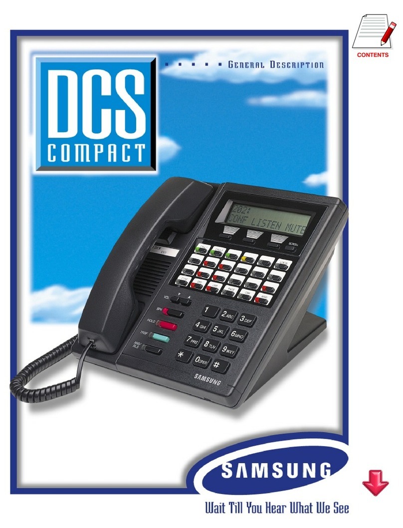
Samsung DCS COMPACT II Operating and maintenance instructions

DCS Compact II General Description
DCS Compact II
GENERAL DESCRIPTION

General Description
DCS-Compact II

DCS Compact II General Description
SAMSUNG ELECTRONICS CO. LTD.
Publication Information
Samsung Electronics reserves the right without prior notice to
revise information in this publication for any reason.
Samsung Electronics also reserves the right without prior notice
to make changes in design or components of equipment as
engineering and manufacturing may warrant.
Copyright 1998
Samsung Electronics Co. Ltd
All rights reserved. No part of this manual may be reproduced in
any form or by any means –graphic, electronic or mechanical,
including recording, taping, photocopying or information retrieval
systems –without express written permission of the publisher of
this material.
March/98

DCS Compact II General Description
i
TABLE OF CONTENTS
CHAPTER 1 System Overview ...........................................1–1~1–6
1.1 Introduction.................................................................................................1–1
1.2 Size and Configuration...............................................................................1–2
1.3Technology...................................................................................................1–5
1.4Programming................................................................................................1–6
CHAPTER 2 Hardware Descriptions................................. 2–1~2–6
2.1 Key Service Unit ..........................................................................................2–1
2.2 Expansion Cabinet.......................................................................................2–2
2.3Interface Cards............................................................................................2–2
2.4Specifications...............................................................................................2–4
CHAPTER 3 Station Equipment.......................................... 3–1~3–5
3.1 LCD 24BModel Keyset (Figure 3–1).........................................................3–1
3.2 STD 24B Model Keyset (Figure 3–2) .........................................................3–2
3.3 LCD 12B Model Keyset (Figure 3–3).........................................................3–3
3.4 STD 12B Model Keyset (Figure 3–4)........................................................3–3
3.5 Enhanced 6BModel Keyset (Figure 3–5)..................................................3–4
3.6 48 Button Add–On Module (AOM) (Figure 3–6, 3–7)............................3–4
3.7 Door Phone Interface Module (DPIM) And Door Phone
(Figure 3–8, 3–9).........................................................................................3–5
CHAPTER 4 Features ........................................................ 4–1~4–34
4.1 System Features ...........................................................................................4–1
4.2 System Feature Descriptions.......................................................................4–2
4.3 Station Features..........................................................................................4–21
4.4 Station Feature Descriptions.....................................................................4–22
4.5 Display Features........................................................................................4–29
4.6 Display Feature Descriptions ...................................................................4–29

DCS Compact II General Description
ii
Figures
1–1DCS Compact II Configuration Matrix Table (with Analogue Trunks)
1–2DCS Compact II Configuration Matrix Table (with Digital Trunks)
1–3DCS Compact II System Configuration
2–1DCS Compact II Key Service Unit
3–1LCD 24B Model Keyset
3–2STD 24B Model Keyset
3–3LCD 12B Model Keyset
3–4STD 12B Model Keyset
3–5Enhanced 6B Model Keyset
3–648 Button Add–on Module
3–7Display Phone and Add–on Module
3–8Door Phone Interface Module
3–9Door Phone

DCS Compact II General Description Chapter 1. System Overview
1-1
CHAPTER 1System Overview
1.1 Introduction
DCS Compact II, Digital Communication System, is a digital telephone system
designed for small to medium–sized businesses. It can operate with the
functionality of a square key system, PABX or a combination of both (hybrid).
DCS Compact II employs the very latest DSP technology (Digital Signal
Processors).
DCS Compact II offers a variety of interface cards that allow connection to the
public telephone network or private networks. These are generally referred to as
trunk cards. Two types of telephones can be connected to the systems. Proprietary
digital phones called "Keysets" connect to digital line interface cards (DLI).
Standard telephone sets generally called "single line telephones"connect to single
line interface cards (SLI). In addition, DLI station ports are used to connect
peripheral devices such as door phones and add–on modules. Miscellaneous
circuits are provided to allow such optional features as external paging, music on
hold, background music, common audible devices, alarms and emergency power
failure telephones.
All DCS keysets utilize a single PCB with surface–mounted components assuring
the highest product quality and long life. Samsung's customary large, easy–to–
read displays and LEDs in the button design make them much easier to use. In
many instances, sophisticated features are made simple through the use of
friendly display prompts or push–on/push–off feature keys.
NOTES
1. 'DCS' is the general term used in the text to refer to all systems. Any differences
between the systems are indicated under separate headings ‘DCS Compact II’
'DCS COMPACT' and 'DCS'.
2. It is not possible to expand from DCS Compact II to a DCS system nor to
expand from DCS Compact to DCS Compact II.

DCS Compact II General Description Chapter 1. System Overview
1-2
1.2 Size and Configuration
The DCS Compact II system consists of the basic Key Service Unit, an Expansion
cabinet and Interface cards and Digital keysets. The Key Service Unit begins with
eight (8) keyset ports expandable to 18 analogue C.O. line ports, or 24lines if 4
BRI cards are used, or 32 stations. In addition, up to 8keyset daughter boards
may be added to the system along with the optional 2 SLI card.
The Expansion cabinet has three Universal slots and one DCS slot for PRI or VM
service, which provides the maximum configuration of 66 ports with analogue
trunk lines or 88 ports with Digital trunk lines.
Two types of telephones can be connected to the system: proprietary digital
stations called "keysets" that connect to DLI (Digital Line Interface) ports and
standard telephone sets, generally called "single line telephones", that connect to
SLI (Single Line Interface) ports.
The system also has an optional Miscellaneous card which provides Music on
Hold facilities,two serial I/O ports and other useful facilities.
The following charts (Figures 1–1 and 1–2) describe configurations using the
basic Key Service Unit (KSU), an Expansion cabinet and expansion cards.
However, by using the DCS's unique keyset daughter boards (KDbs), which are
installed in the base of a digital keyset, the capacity of the system can be increased
by one station per KDb. Installing a KDb–DLI adds another digital port while a
KDb–SLI adds a single line port. Mix and match these two types of KDb to get up
to a total of 8KDbs in the system. Using this method allows the DCS Compact II
to expand to a maximum of 64 stations. Adding the optional 2 SLI card to the
KSU provides a further two SLI ports. The combination of the basic 008 KSU plus
three expansion cards in the KSU plus three expansion cards and one DCS card in
the Expansion cabinet plus 8KDbs plus a 2 SLI card provides a maximum
configuration of 88 ports plus Miscellaneous card.
Configuration Notes
1. Only one 2 SLI card can be installed in the system.
2. Only one Miscellaneous card can be installed in the system.
3. Only three expansion cards can be installed in the Key Service Unit and the
additional three expansion cards and a DCS card like as PRI can be installed in
the Expansion cabinet.
4. Only 8KDbs can be installed in the keysets connected to the 008 Basic KSU.
5. If a PRI card is installed in the DCS card slot, the last expansion slot of the
Expansion cabinet should remain blank.
DCS Compact II General Description Chapter 1. System Overview
1-3
Figure 1–1 DCS Compact II Configuration Matrix Table
(with Analogue Trunks)
8 16 18 26 34 42 50 58 66
Figure 1–2 DCS Compact II Configuration Matrix Table
(with Digital Trunks)
8 16 18 26 34 42 50 58 66
36
30
24
18
12
6
0
Two Cabinets
Trunk Lines
Station Lines
KSU
70
40
32
24
16
8
0
Two Cabinets
Trunk Lines
Station Lines
KSU

DCS Compact II General Description Chapter 1. System Overview
1-4
Figure 1–3DCS Compact II System Configuration
DCS Compact II Configuration Notes
1. Only one 2 SLI card can be installed in the KSU.
2. Only one Misc card can be installed in the KSU.
3. Only three expansion cards can be installed in the KSU and the additional can
be added in the Expansion cabinet when expanded.
4. Only 8KDbs can be installed in the keysets connected to the Basic KSU.
5. ISDN cards(BRI and PRI) require a PLL card installed in the KSU.
6. A PRI card installed in the DCS slot of the Expansion cabinet requires the last
expansion slot(the third one) remains blank.
7.A maximum of 40 keysets can be installed.
PLL
P4
D
C
S
S
L
O
T

DCS Compact II General Description Chapter 1. System Overview
1-5
1.3 Technology
Switching
System switching is accomplished by means of a custom IC "engine" that
provides 256 switchable digital channels. The engine is controlled by its own
16–bit MotorolaMC 68000 microprocessor and switching control program.
Each of the 256 digital channels is automatically assigned to carry voice or data
as required by system operation in a PCM format.
In addition to the 256 channels mentioned above, the systems also utilize Digital
Signal Processors (DSPs). Each DSP may be configured by the switching control
program as a DTMF sender, a DTMF receiver or as a C.O. tone detector on a
per–call basis. Each engine chip contains 4DSP channels.
Four additional DSPs are added when a MISC card is installed. This means that
the system contains a total of 8DSP channels when fully expanded. The DSP
channels are fully shared throughout the system as a common resource.
Memory
The systems operate using stored program control. This program is stored in
EPROM chips. All specific customer data is stored in random access memory
(RAM) which is protected against the loss of AC power to the system by an on–
board battery backup system.
Microprocessors
DCS Compact II uses distributed processing. The primary processor of the
system is a 16–bit MotorolaMC68000 operating at a clock speed of 16 MHz.
Secondary processing is in the some special cards like as BRI and also done in
the keysets. The digital keyset uses a Hitachi H8 processor for data
communication within the DCS Compact II.

DCS Compact II General Description Chapter 1. System Overview
1-6
1.4 Programming
DCS Compact II is self–configuring. This means that when the power is switched
ON, the system reads the types and locations of all installed cards and telephones
and assigns default data to them. This data provides for system operation within
seconds after power is switched ON. All trunks and stations are assigned
according to the default numbering plan. This numbering plan is flexible and
may be changed to suit customer requirements. The installing technician
customizes this default data to meet the end user's requirements.
The systems can be programmed from any LCD display keyset without
interrupting system operation. There are three levels of programming:
technician, customer and station. The technician level has access to all programs
and can allow the customer access to system programs as needed. The
technician and customer access are controlled by different security passcodes
and access procedures.
DCS Compact II also allows the use of a proprietary computer program called
PCMMC. This permits a technician to program the system using a personal
computer. PCMMC can be used on–site to modify the customer database or to
download (save) the entire customer database to a file. This file can then be
saved as a backup and be uploaded when required to restore the database.
Through the use of modems, PCMMC can access a DCS Compact II system
remotely (off–site) to make database changes or perform uploads or downloads
of the customer database as if the technician were on–site.

DCS Compact II General Description Chapter 2. Hardware Descriptions
2-1
CHAPTER 2 Hardware Descriptions
2.1 Key Service Unit (KP70D–M1/)
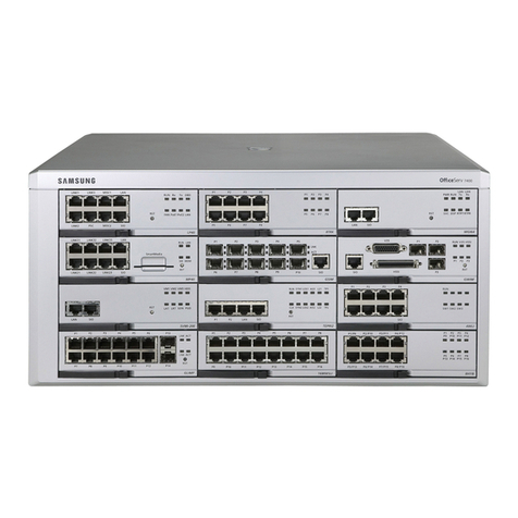
The DCS Compact II Key Service Unit
(KSU, Figure 2–1) is a single metal
cabinet containing the following:
•A power supply
•Processing and switching
•Eight 2B+D digital keyset interfaces
•A removable MEM card, containing
2Mbyte Program memory, 512Kbyte Data
memory with a back–up super capacitor, real
time clock, a monitor LED and a RAM clear
switch
•One Internal Music source or an External
Music interface for Music–on–Hold and Back–ground Music
•One External Page interfaces
•One general–purpose Dry contact
•Three universal expansion slots, a MEM card slot, a 2 SLI card slot and a
MISC card slot
•2 Champ connectors for external connections and other connectors for the
Expansion cabinet and the Ring Generator Unit
Ring Generator Unit RGU1 (KP70D–BRG1/) or
RGU2 (KP70D–BRG2/)
Two kinds of sinusoidal–waveform Ring Generator Units are available. KP70D–
BRG1 drives 3W ring signals while the other provides 20W ring signals. The
larger unit is required when a large number of single line telephones are
operation behind the system.
Figure 2
–
1

DCS Compact II General Description Chapter 2. Hardware Descriptions
2-2
MISC card MISC 1 (KP70D–BMI1/) or
MISC 2 (KP70D–BMI2/)
One dedicated slot in the Basic KSU is for an MISC card and two kinds of MISC
cards are available. The MISC 1 card contains one additional External Music
Interface for MOH or BGM, one additional External Page Interface, one Alarm
Sensor Detection circuitry, 4 channels DTMF receiver, three General–purpose
Dry contact relays, two RS232C Serial interfaces with connectors for PCMMC
and SMDR and MODEM card interface. The MISC 2 card is similar to the MISC
1 card but is also equipped with a built–in 4–ch AA function.
It is strongly recommended that this card be used in situations requiring heavy
single line telephone use.
MODEM card (KP70D–BMO/)
One built–in MODEM card can be installed in a MISC card.
PLL card (KP70D–BPL/)
Any ISDN card, that is a BRI or a PRI, requires the PLL card which can be installed
in a dedicated place on the KSU motherboard.
2.2 Expansion Cabinet (KP70D–M2/)
One metal Expansion cabinet can be attached to the Key Service Unit for
expansion. It consists of three Universal expansion slots and one DCS card slot
for PRI or VM. The Expansion cabinet connects to the KSU via a 64–pin flat
cable, two 2–wire power connections and a F–GND connection. It contains a
50–pin champ connector for external connections.
2.3 Interface Cards
2 SLI card (KP24D–B2S/)
The 2 SLI card is installed in a dedicated slot on the KSU motherboard. The card
provides two single line telephone interfaces equipped with Long Line protection
and the ability to provide a loop disconnect signal.

DCS Compact II General Description Chapter 2. Hardware Descriptions
2-3
3 TRK card (KP70D–B3T/)
The 3TRK card provides three loop start C.O. interfaces with optional Caller ID
relays.The first two C.O. interfaces are equipped with PFT relays. Each
interface contains an interface for MPD or PRS which is optional. The MPD or
PRS hybrid chips of the DCS system can be used.
6 TRK card (KP70D–B6T/)
The 6TRK card provides six loop start C.O. interfaces. The first two C.O.
interfaces are equipped with PFT relays. Each interface contains an interface for
MPD or PRS which is optional. The MPD or PRS hybrid chips of the DCS system
can be used.
4 BRI card (KP70D–B4B/)
The 4BRI card contains four Basic Rate access ports, i.e. eight ISDN channels.
Protocol is compatible for Euro–ISDN BRI. For S0 application, power feeding to
ports is selectable by programming.
2 BRI card (KP70D–B2B/)
The 2BRI card contains two Basic Rate access ports, i.e. four ISDN channels.
Protocol is compatible for Euro–ISDN BRI. For S0 application, power feeding to
ports is selectable by programming.
PRI card (KP70D–BP/)
The PRI card contains one Primary Rate access ports, i.e. thirty ISDN channels.
Protocol is compatible for Euro–ISDN PRI.
8 DLI card (KP70D–B8D/)
The 8 DLI card provides eight DLI ports.
8 SLI card (KP70D–B8S/)
The 8 SLI card provides eight SLI ports for industry–standard single line
telephones and the ability to provide a loop disconnect signal. Please note that
this card does not provide Long Line protection.

DCS Compact II General Description Chapter 2. Hardware Descriptions
2-4
6 MWSLI card (KP70D–B6S2/) Available from July, 1998
The 6 MWSLI card provides six SLI ports for industry–standard single line
telephones and the ability to provide a loop disconnect signal and a message
waiting signal.Please note that this card does not provide Long Line protection.
KDb–DLI, KDb–SLI card
The KDb–DLI board or KDb–SLI board, if installed in a digital keyset connecting
to the Basic KSU, provides a second DLI or SLI port.
2.4 Specifications
The following tables provide technical data for the DCS Compact II hybrid/key
telephone system.
Electrical Specifications
AC INPUT 220 VAC ±20%, 48–63 Hz
or Free Input Voltage for some countries.
POWER CONSUMPTION (MAX) 100 WATTS MAX
DC OUTPUT FUSE RATING 2.0 AMP
+5 VOLTS 2.5AMPS MAX
–5 VOLTS 0.5 AMPS MAX
(on the Motherboard)
–55 VOLTS 1.2AMPS MAX
–54 VOLTS 0.4 AMPS MAX

DCS Compact II General Description Chapter 2. Hardware Descriptions
2-5
Dimensions And Weights
Height(mm) Width(mm) Depth(mm) Weight(kg)
SINGLE CABINET 464 365 148 7.5
TWO CABINETS 464 467 148 12.5
DIGITAL KEYSET (ALL MODELS)
75 243 220 1.1
ADD–ON MODULE 71 133 220 0.4
DPIM 120 91 28 0.2
DOOR PHONE 127 99 30 0.2
Environmental Limits
OPERATING TEMPERATURE 0–40 °C
STORAGE TEMPERATURE –10.5 –70 °C
Cable Requirements
EQUIPMENT CABLE AWG MAX
FEET
MAX METERS
DIGITAL KEYSETS 1 PR. TWISTED 24 1300 400
ADD–ON MODULES
1 PR. TWISTED 24 1300 400
SINGLE–LINE STATION
1 PR. TWISTED 24 3000 1 KM
DOOR PHONE 2 PR. TWISTED 24 330* 100
NOTE
This is the maximum length of the cable between the door phone and the DPIM.
The DPIM can be installed up to 274 cable meters from the KSU.
System Tones
Tone Frequencies Cadence
Dial Tone 350 + 440 Hz Continuous
Ring Back Tone 440 + 480 Hz 1 sec on + 3 sec off
Busy Tone 480 + 620 Hz 0.5 sec on + 0.5 sec off
DND/No More Tone 480 + 620 Hz 0.25 sec on + 0.25 sec off
Error Tone 480 + 620 Hz 0.25 sec of each tone
Confirmation Tone 350 + 440 Hz
Three bursts of tone 0.1 sec on + 0.1
sec
Transfer/CONF 350 + 440 Hz 0.1 sec on + 0.1 sec off
NOTE
The details of system tones may vary according to the specifications of each
country.

DCS Compact II General Description Chapter 2. Hardware Descriptions
2-6
Keyset LED Indications (Except Basic 6B keyset)
Condition LED Color LED On LED Off
Line Idle Off –OFF
Line In Use Red/Green Steady –
Recall Amber 500 ms 500 ms
Call On Hold Red/Green 500 ms 500 ms
Ringing C.O. Call Red/Green 100 ms 100 ms
Ringing Internal Call Green 100 ms 100 ms
DND Indication Red 100 ms ON/100 ms OFF
for 500 ms 500 ms
RESERVE POWER DURATION ESTIMATES (minutes)*
UPS Capacity In Volt Amps (VA)
No. of Stations 250 400 450 600 900 1250 2000
4 65 160 200 245 360 490 930
8 45 110 135 160 240 320 625
12 40 90 115 140 200 280 535
16 30 75 90 110 160 220 415
24 25 50 70 85 120 175 380
32 20 45 60 75 100 150 330
NOTE
These are approximate values based on an idle system. The greater the C.O. line
activity on the system, the lower these readings will become. In addition,
specific UPS devices, due to their internal construction, can have greater or lesser
values.

DCS Compact II General Description Chapter 3. Station Equipment
3-1
CHAPTER 3 Station Equipment
3.1 LCD 24B Model Keyset (Figure 3–1)
•Built–in speakerphone
•24 programmable soft keys (16 with tri–colored LEDs)
•Eight fixed–function keys
•32–character display (2 x 16) with three associated soft keys and a scroll key
•UP/DOWN buttons for digital control of speaker, handset and ringer
volumes
•Eight selectable ring tones per keyset
•Desk–mounted or wall–mounted
•Available in charcoal
Figure 3–1

DCS Compact II General Description Chapter 3. Station Equipment
3-2
3.2 STD 24B Model Keyset (Figure 3–2)
•Built–in speakerphone
•24 programmable soft keys (16 with tri–colored LEDs)
•Eight fixed–function keys
•UP/DOWN buttons for digital control of speaker, handset and ringer
volumes
•Eight selectable ring tones per keyset
•Desk–mounted or wall–mounted
•Available in charcoal
Figure 3–2

DCS Compact II General Description Chapter 3. Station Equipment
3-3
3-3 LCD 12B Model Keyset (Figure 3–3 )
•Built–in speakerphone
•12 programmable soft keys (8with tri–colored LEDs)
•Eight fixed–function keys
•32–character display (2 x 16) with three associated soft keys and a scroll key
•UP/DOWN buttons for digital control of speaker, handset and ringer
volumes
•Eight selectable ring tones per keyset
•Desk–mounted or wall–mounted
•Available in charcoal
3-4 STD 12B Model Keyset (Figure 3–4)
•Built–in speakerphone
•12 programmable soft keys (8with tri–colored LEDs)
•Eight fixed function keys
•UP/DOWN buttons for digital control of speaker, handset and ringer
volumes
•Eight selectable ring tones per keyset
•Desk–mounted or wall–mounted
•Available in charcoal
Figure 3–3Figure 3–4
Table of contents
Other Samsung Telephone Accessories manuals

Samsung
Samsung EF-NG991 User manual

Samsung
Samsung iDCS 28D User manual

Samsung
Samsung DCS Compact User manual

Samsung
Samsung ET-CG930 User manual

Samsung
Samsung DCS 70 User manual

Samsung
Samsung Vehicle Dock User manual

Samsung
Samsung NX-828 User manual

Samsung
Samsung SVMi-4 Guide

Samsung
Samsung DS 5000 Series User manual

Samsung
Samsung Ubigate iBG3026 User manual
Popular Telephone Accessories manuals by other brands

Gigaset
Gigaset C34 manual

Chamberlain
Chamberlain LiftMaster MUOTIU-EX installation instructions

BELGACOM
BELGACOM LINKSYS SPA942 Quick reference guide

Cisco
Cisco CP-7914 - 7914 - Key Expansion Module quick start guide

Polycom
Polycom Vortex EF2210 Brochure & specs

P3 International
P3 International P5045 Specifications