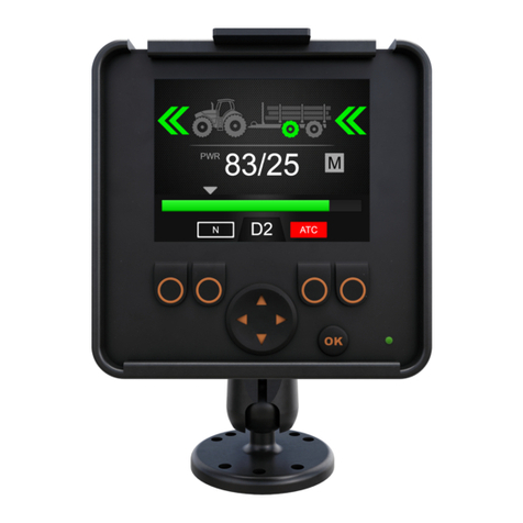
Black Bruin CTR101 User manual

Operation manual
CTR101 control system

Contents
1 General instructions......................................................................... 3
1.1 About the manual............................................................................................................................................3
1.2 Intended use..................................................................................................................................................... 3
1.3 Warranty............................................................................................................................................................. 3
1.4 Product identication..................................................................................................................................... 3
1.5 Revision comments.........................................................................................................................................4
2 Safety instructions........................................................................... 5
2.1 Warning symbols..............................................................................................................................................5
3 Product description.......................................................................... 6
3.1 Working principle..............................................................................................................................................6
3.2 Driving mode.....................................................................................................................................................6
3.3 HDC function (Hill descent control) (option).............................................................................................7
3.4 Freewheeling mode.........................................................................................................................................7
4 Getting started.................................................................................. 8
4.1 Display and user interface............................................................................................................................ 8
4.2 Power-up the control system.......................................................................................................................8
4.3 Menu..................................................................................................................................................................10
5 Main view elements......................................................................... 14
5.1 Main view at the initial state....................................................................................................................... 14
5.2 Status bar - Alarms and warnings.............................................................................................................14
5.3 Tractive power and HDC level indication..................................................................................................15
5.4 Operating mode indication.......................................................................................................................... 16
6 Operating functions........................................................................ 18
6.1 Tractive power level selection.....................................................................................................................18
6.2 Driving and freewheeling mode selection (F2)...................................................................................... 18
6.3 Braking in driving mode................................................................................................................................19
6.4 Assisting traction control (ATC), (F3)........................................................................................................ 21
6.5 Auxiliary valve control (AUX), (F1) (option)..............................................................................................23
6.6 Keypad lock.....................................................................................................................................................23
7 User parameters..............................................................................25
8 Troubleshooting.............................................................................. 28
8.1 Display status indicator LED....................................................................................................................... 31
8.2 Control device segment-display................................................................................................................31
Contents
2 Operation manual

General instructions
About the manual
This manual contains the instructions for the operation of Black Bruin CTR101 control
system. Obey these instructions when you use the product.
Black Bruin CTR101 control system is part of the On-Demand Drive System
transmission solution. The On-Demand Drive System product manual describes the
design and installation instructions of the transmission solution.
All information is based on information that was available at the time that this manual
was written. The manufacturer reserves the right to change the content of this
manual without further notice.
Please visit www.blackbruin.com for the most recent version of this manual. The
product datasheets and the 3D-models are available from the manufacturer by
request.
Intended use
Black Bruin On-Demand Drive System is a transmission solution for tractor-driven
trailers and working equipment.
On-Demand Drive System is very applicable for equipment that periodically requires
additional power and is towed without hydraulics.
On-Demand Drive System is designed for o-road driving and it must be powered o
when you drive in road trac.
Black Bruin CTR101 control system is only applicable to use together with the
freewheeling Black Bruin motors.
Warranty
Check the package and the product for transport damage when receiving goods. The
package is not meant for long term storage; protect the product appropriately.
Do not dismantle the product. The warranty is void if the product has been
disassembled.
The manufacturer is not responsible for damages resulting from misinterpreted, non-
compliance, incorrect, or improper use of the product that goes against the
instructions given in this document.
Product identication
The product has an identication plate. The identication plate has the information
that follows:
Figure 1. Identication plate of the control system.
1. Model
2. Part number
3. Serial number
1
1.1
1.2
1.3
1.4
General instructions
Operation manual 3

Revision comments
08.06.2020 (Software version 03.02.00) - This manual is published.
1.5
General instructions
4 Operation manual

Safety instructions
The instructions that follow apply to all procedures related to the product. Read these
instructions fully and follow them carefully.
• Use necessary personal protective equipment when you do work with the product.
• Use correct support with the product. Make sure that the product cannot
accidentally fall or turn.
• Use only appropriate equipment and attachments when you lift and move the
product.
• Make sure that it is not possible to pressurize the hydraulic lines during product
installation and maintenance procedures.
• During the operation the product temperature can be over 60 ºC (140 °F). Hot
surfaces can burn you. Be careful of hot hydraulic uid when you disconnect the
hydraulic connections.
Warning symbols
The following symbols are used in this manual:
Note:
Useful information.
Danger:
Danger of death or injury.
Attention:
May cause damage to the product.
2
2.1
Safety instructions
Operation manual 5

Product description
Working principle
The Black Bruin On-Demand Drive System can use hydraulic motors in the operating
modes that follow:
• Driving mode
• Driving mode with HDC function (Hill descent control) (option)
• Freewheeling mode.
The chapters that follow give the working principles of these modes.
Driving mode
In the driving mode the driver selects the driving direction and the tractive power
level toward which the motors operate. In this mode the motors help the vehicle to
move. You can adjust the power level to the driving conditions. The power level stays
constant also if the speed changes. When the tractor brakes the system reduces the
working pressure to the minimum level and the hydraulic motors do not have tractive
power.
2-speed hydraulic motors give wider speed range for the hydraulic drive.
If the vehicle wheels slip, the assisting traction control ATC increases the torque on
the wheels that have more traction.
Typical situations to operate in the driving mode are:
• Driving up steep slopes
• Moving rearward on steep slopes
• Going across obstacles
• Driving on slippery or soft surfaces.
3
3.1
3.2
Product description
6 Operation manual

HDC function (Hill descent control) (option)
The HDC function helps when you drive the vehicle down on steep slopes, in both
forward and reverse driving modes.
When the HDC function is active, the wheel motors resist the wheel movement to the
driving direction. You can adjust the HDC power level during the operation.
Typical situations for the use of the HDC function are:
• Driving down steep slopes
HDC function o, vehicle accelerates.
• Driving down steep slopes
HDC function on, function helps the
vehicle to maintain the speed.
• Moving rearward on steep slopes
HDC function o, vehicle accelerates.
• Moving rearward on steep slopes
HDC function on, function helps the
vehicle to maintain the speed.
Freewheeling mode
In the freewheeling mode you can freewheel the motors without energy loss or
overheating problems (stationary cylinder block - no centrifugal forces), even at high
speeds. You can engage the drive again during movement when the speed is in the
working range.
If the pressure level is not sucient due to increased driving speed, the control
system automatically switches to freewheeling. This protects the motor from
overloading.
The operator can also manually change the mode to freewheeling.
Typical situations to operate in the freewheeling mode are:
•When you drive on road
• When you do work above the maximum working speed range
• When the working conditions are easy.
3.3
3.4
Product description
Operation manual 7

Getting started
Display and user interface
The display operates as a control element for the drive system. It also shows
information to the user about the operation of the system.
The functions of the F1 - F4 buttons change together with the view and the mode.
The signs that show at the bottom of the display refer to the related functions of the
F1 - F4 buttons.
The background color of the sign shows if the mode of the function is ON or OFF . In
the gure below the function D2 for button F2 is ON. The background color of the
sign is grey.
ATC
D2 N
AUX
PWR 0/0
OK
1.
2.
3.
8.
7.
6.
5.
4.
OK
Figure 2. The display buttons and the user interface.
1F1 2F2
3
Selection arrows (left, right)
Selection arrows (up, down) 4 Function signs for F1 - F4 buttons
5F3 6F4
7 Status indicator light 8 OK
Power-up the control system
After the control system power-up, the start-up view comes on and the program
version shows on the display.
4
4.1
4.2
Getting started
8 Operation manual

OK
03.01.05
Figure 3. Start-up view.
The brake-signal check-dialog view shows on the display.
OK
Signal check: Press brake
Figure 4. Brake-signal check-dialog view.
Operating functions and the main view are not available until you press the brake and
the system detects the brake signal. But you can open the main menu from the
brake-signal check-dialog view.
When you use the control system for the rst time, do a preliminary check of the
settings before you use the operating functions. It is very important that you adjust
the maximum pressure level rst.
You can also open the main menu from the main view. To open the main menu, push
the F4 ( ) button.
To continue to the main view, press the brake.
If the brake-signal check-dialog view does not go out of view when you press the
brake, see chapter Troubleshooting on page 28.
The brake-signal check-dialog view shows after each power-up, after which the
system is in the freewheeling (N) mode.
Getting started
Operation manual 9

Menu
1. Main menu
To open the main menu from the main view,
push the F4 button ( ).
Note:
The main menu is available only
when the system is in the free-
wheeling mode.
D2 N
AUX ATC
PWR 0/0
OK
2. Language and display brightness
You can adjust the display brightness and
change the control system language from the
main menu.
• Arrow buttons up/down: Select the value
you want to adjust.
• Arrow buttons left/right: Adjust the val-
ues.
The selection of language has an eect on
the language of the user interface and the
parameter names.
Brightness 64
Settings
Language English
i
OK
4.3
Getting started
10 Operation manual

3. Parameters and system information me-
nus
Parameters menu shows the settings related
to the operation of the system. You can adjust
these settings.
Information menu shows the information
about the system and operations, for example
the operating hours and the latest fault mes-
sages.
• In the main menu push the F1 button to go
to the user parameters menu.
• In the main menu push the F2 button to
go to the system information menu.
• Push the F4 button to exit the main menu.
Brightness 64
Settings
Language English
i
OK
4. Parameter selections
Parameter names are in the same language as
the user interface. See chapter User parame-
ters on page 25 for the detailed information
on the parameters and their possible values.
• Arrow buttons up/down: Select the pa-
rameter you want to adjust.
• Arrow buttons left/right: Adjust the pa-
rameter values.
2-speed function 1
Parameters
ATC max. time [s] 5
Minimum pressure level [bar] 15
Minimum pressure delay [ms] 300
Power change ramp 2
Maximum pressure level [bar] 320
Drive activation ramp 2
Shifting ramp 2
x1
1/2
OK
Getting started
Operation manual 11

5. Parameter selections, page scrolling
If the system has the HDC function (Hill de-
scent control) the parameter list includes two
pages. You can see the page number and the
total number of pages at the top right corner
of the display. Push the buttons F1 and F2 to
scroll the pages.
• Previous page: F1
• Next page: F2
HDC enabled 1
Parameters
HDC level 1, pressure [bar] 80
HDC level 2, pressure [bar] 120
HDC level 3, pressure [bar] 180
HDC level 4, pressure [bar] 270
HDC, activation level 1
HDC, ramp 2
x1
2/2
OK
6. Parameter multiplier
The multiplier shows the step value in which
you can change the parameter value. You can
change the step value when you have to ad-
just large values. The multiplier values are x1,
x10, x100 and x1000.
• Push the F3 button to change the multipli-
er value. The sign above the button shows
the selected multiplier value.
• Push the F4 button to exit the parameter
menu.
2-speed function 1
Parameters
ATC max. time [s] 5
Minimum pressure level [bar] 15
Minimum pressure delay [ms] 300
Power change ramp 2
Maximum pressure level [bar] 320
Drive activation ramp 2
Shifting ramp 2
x1
1/2
OK
Getting started
12 Operation manual

7. System information
In the main menu push the F2 button to go to
the system information menu.
Information menu shows the information
about the system and operations.
This information is necessary for example for
troubleshooting and support requests.
• Model series: Control system model:
CTR101
• Sw Version: Software version numbers are
as follows:
1. Control device software version
2. Display software version
3. 4WD-auxiliary device software ver-
sion (only in 4WD systems).
• Last error: Latest error message. See
chapter Troubleshooting on page 28 for
the list of alarm codes.
• Safestate occurred: How many times the
system has been to the safe state.
• Working hours: System operating hours
(the display has been on).
• Forward: The number of times the system
has been in the forward driving mode.
• Backward: The number of times the sys-
tem has been in the reverse driving mode.
• TOW: The number of times the system has
been in the freewheeling mode.
• Push and hold the F2 and F3 buttons at
the same time to reset the counters.
• Push the F4 button to exit the information
menu.
Model series
Coil_failure_PDB
Safestate occurred 1
Working hours 41
Forward 18
Backward 3
TOW 18
CTR101
Sw Version
Last error
03.01.05 03.01.05 03.01.05
OK
Getting started
Operation manual 13

Main view elements
Main view at the initial state
You can manage the operating functions from the main view.
ATC
D2
AUX N
PWR 0/0
Figure 5. The main view after the power-up. The system is in the freewheeling mode. If
the system does not have the auxiliary valve control, the AUX icon does not show. If
the system has the 2-speed motors, the D2 icon shows.
Note:
The trailer icon can be dierent from the one in the gure.
Status bar - Alarms and warnings
The status bar at the top of the main view shows all alarms and warnings.
The background color of the status bar is:
• Black for the alarms
• Grey for the warnings.
Red background color of the OK icon at the top of the main view means that you must
reset the alarm before you can activate the drive. If you have removed the cause for
the alarm, push the OK button to reset the alarm. See chapter Troubleshooting on
page 28 for more detailed information on the alarms.
5
5.1
5.2
Main view elements
14 Operation manual

ATC
D2 N
3: Sensor_failure_pressure_A
PWR 0/50
OK
OK
Figure 6. Status bar - Alarms and warnings.
Tractive power and HDC level indication
Tractive power level is shown on a scale of 0 -100%. Full power level is related to the
maximum pressure level specied in the parameters.
If the system has the HDC function (Hill descent control), the HDC level is also related
to the maximum pressure level specied in the parameters.
ATC
D2 D1
PWR 23/25
3.
1.
3. 2.
2.
Figure 7. Tractive power and HDC level indication.
1Mode: PWR/HDC
Shows the active mode on the display:
•PWR: Tractive power adjustment. The
values on the display show the trac-
tive power level.
•HDC: Hill descent control adjustment
(only in systems that have the HDC
function). The values on the display
show the HDC function intensity.
2Selected level:
• The number shows the set value.
• The grey arrow above the colored
power bar shows the set value.
5.3
Main view elements
Operation manual 15

3Measured level:
• The number shows the measured val-
ue
• The colored power bar below the num-
bers shows the measured value:
• Green: PWR
• Red: HDC.
Measured and set values are percentages from the maximum pressure level that is
specied in the settings (Maximum pressure level [bar]).
For example, with the numbers shown in the gure, the calculation for 200 bar
system gives the pressure levels as follows:
• Selected level 25% => 200 bar x 25/100 = 50 bar
• Measured level 23% => 200 bar x 23/100 = 46 bar.
Operating mode indication
ATC
ND2
PWR 23/25
3.
1.
4.
2.
D2
Figure 8. Operating mode indication.
1Arrows
Show the operation and operating modes
as follows:
•No arrows: Freewheeling
•Green arrows:
• Drive is active to the direction of
the arrows.
• The double arrows show, if the D2
gear is on.
•Intermittent arrows green / grey:
• During braking
• After braking before the tractive
power comes back on.
2Color of the trailer wheels
Show the hub motor operation modes as
follows:
•2WD system: The color of the front
wheel symbol changes.
•4WD system: The colors of the two
wheel symbols change.
•The wheel colors:
•Grey: Freewheeling
•Green: Drive active, driving mode
•Red: Drive active, braking active
•System without HDC: Tractive
power reduced to minimum lev-
el
•System with HDC: HDC func-
tion active.
5.4
Main view elements
16 Operation manual

3Current gear
•N: Freewheeling
•D1: Drive forward, speed range 1
•D2: Drive forward, speed range 2
•R: Drive reverse.
4Operating mode icons
The icons come into view to show system
mode and mode changes:
•N: Freewheeling is active
•AUX: Auxiliary valve control is active
•: Tractor braking is active
• D1, D2 and R icons come into view only
during the change. The icons stay out
of view during the drive.
Main view elements
Operation manual 17

Operating functions
Tractive power level selection
You can use the arrow buttons to change the power level (left, to decrease the level
or right, to increase the level). Power levels are 0, 25, 50, 75 and 100% of the
maximum level. You can set the value in the freewheeling mode and change it during
the driving mode.
• Decrease power: <
• Increase power: >
The green bar shows the measured value and the grey arrow above it shows the set
value.
ATC
D2 N
AUX
PWR 23/50
OK
Figure 9. Tractive power level selection. Measured value/set value: 23/50.
Driving and freewheeling mode selection (F2)
The gear indicator at the bottom of the screen shows the current mode of the drive
system.
Use the up/down arrows and the F2 button to change between the freewheeling (N)
and the driving modes (D1, D2 and R).
Note:
Do not activate the drive if the driving speed is above the working speed
range.
If you drive forward, you can change directly from freewheeling to D2
speed range.
Note:
Do not activate the drive to the opposite direction when the tractor
moves.
6
6.1
6.2
Operating functions
18 Operation manual

Note:
Do not use the driving modes in road trac.
ATC
ND1
PWR 49/50
D1 N
ATC
D2 N
AUX
PWR 0/50
N
N
NR
PWR 49/50
R
ATC
ATC
D2 N
AUX
PWR 0/50
AUX
AUX
ATC
ND2
PWR 49/50
D2
F2
F2
b)
a) N
D2 D2
F2
F1
F1
AUX
AUX
b)
F2
N
a)
Figure 10. Operating mode selection.
Automatic freewheeling (N)
If the pressure level is not sucient due to increased driving speed, the system
automatically switches to the freewheeling mode.
The parameter table (see chapter User parameters on page 25) gives the
parameters that have an eect on the automatic freewheeling function.
The status bar at the top of the main view shows warning "6: Pressure_low" when
the system automatically switches to freewheeling.
Push the OK button to remove the warning. The warning also goes out of view when
the drive is activated again.
Braking in driving mode
The system without the HDC function
When the tractor brakes the tractive power reduces to the lowest level. The brake
symbol comes into view and the trailer wheel color changes to red. The direction
arrows blink to show the reduced power level. After the braking, the tractive power
level stays at the minimum level. To return the tractive power to the selected leve:
• If the tractor moves forward, push the arrow button up
• If the tractor moves rearward, push the arrow button down.
6.3
Operating functions
Operation manual 19

ATC
ND1
PWR 8/25
OK
Figure 11. Braking in driving mode.
The system with the HDC function (Hill descent control)
If the driving mode is either forward or reverse, the HDC function activates when the
tractor brakes. The HDC text comes into view and the power bar color changes to red.
When the HDC function operates the values shown on the display represent the
intensity of the HDC function instead of the tractive power. During braking you can
adjust the level with the left and right arrow buttons. There are four intensity presets
and you can select their levels in the parameter menu.
You can also change the speed range during the HDC use. If the speed is low, the D1
speed range makes the deceleration stronger. The HDC function stops after the
braking. To return the tractive power to the selected level:
• If the tractor moves forward, push the arrow button up
• If the tractor moves rearward, push the arrow button down.
You can use the HDC during all driving speeds. If the ow to the motors is not
sucient for the driving speed, the vehicle loses the deceleration power. If the speed
is too high during the HDC function, the system shows the warning Overspeed.
Note:
Continuous use of the HDC function can cause the hydraulic uid
temperature to increase.
It is important to monitor the uid temperature during use.
Operating functions
20 Operation manual
Table of contents
Other Black Bruin Control System manuals
Popular Control System manuals by other brands
Norac
Norac UC5 ECHO Display Kit installation manual

Woodward
Woodward SECM112 installation manual
Cistermiser
Cistermiser sensazone SZ/IF installation guide
Festo
Festo CPX-E Instructions & Operating
Hypertherm
Hypertherm EDGE Pro Ti instruction manual

Meccanica SCOTTI
Meccanica SCOTTI CNC Table Programming manual
Eaton
Eaton Crouse-Hinds GHG 61 R Series operating instructions
Crestron
Crestron FlipTop FT2 Series quick start
flamco
flamco Logotherm LogoTronic Hub OTC operating instructions
Mitsubishi Electric
Mitsubishi Electric M800VW Series Programming manual
TMP
TMP Evo Chev installation guide
Rath
Rath 2500-12SPRVSR Installation & operation manual
