Black Bruin On-Demand User manual

Product manual
On-Demand Drive System
CTR101 / CTR201 and CVM120 / CVU200 valves

Contents
1 General instructions......................................................................... 4
1.1 About the manual............................................................................................................................................4
1.2 Intended use.....................................................................................................................................................4
1.3 Warranty............................................................................................................................................................. 5
1.4 Product identication..................................................................................................................................... 5
1.5 Revision comments.........................................................................................................................................5
2 Safety instructions........................................................................... 6
2.1 Warning symbols..............................................................................................................................................6
3 Product description.......................................................................... 7
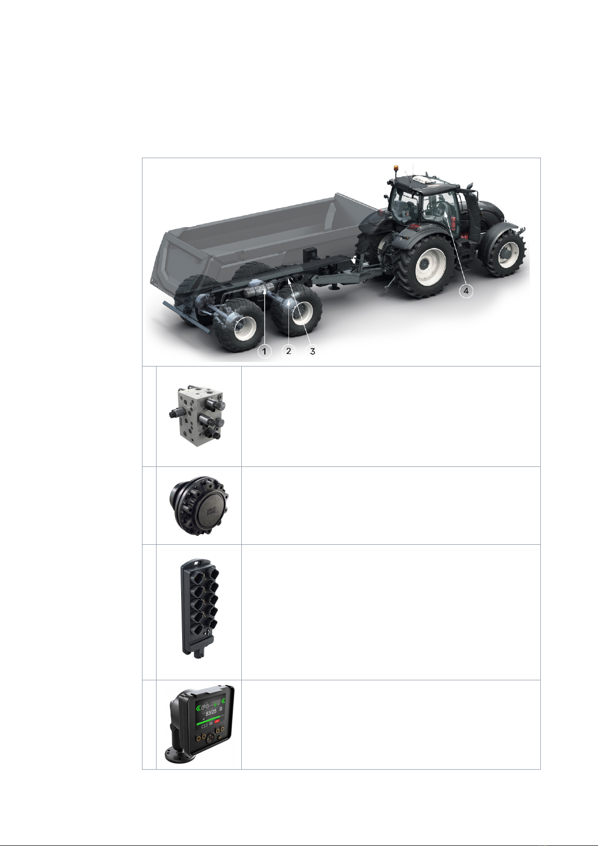
3.1 Main components of the On-Demand Drive System..............................................................................7
3.2 Control systems............................................................................................................................................... 8
3.3 Working principle..............................................................................................................................................8
3.4 Driving mode.....................................................................................................................................................8
3.5 HDC function (Hill descent control) (option).............................................................................................9
3.6 Freewheeling mode.......................................................................................................................................10
4 System design.................................................................................. 11
4.1 Hydraulic motors.............................................................................................................................................11
4.2 Valves................................................................................................................................................................ 12
4.2.1 Valve models.................................................................................................................................12
4.2.2 Valve functions.............................................................................................................................12
4.3 Hydraulic system............................................................................................................................................13
4.4 Hydraulic connections..................................................................................................................................14
4.5 Port pairs.......................................................................................................................................................... 17
5 Control system.................................................................................18
5.1 Model series of the control system........................................................................................................... 18
5.2 Product identication code......................................................................................................................... 19
5.3 Control system connections....................................................................................................................... 19
5.3.1 Important notes........................................................................................................................... 19
5.3.2 Control system connection diagrams................................................................................... 20
5.3.3 Display cable with extension................................................................................................... 22
5.3.4 Pressure sensor cables............................................................................................................. 22
5.3.5 Brake signal cable.......................................................................................................................23
5.3.6 Valve cable, Y...............................................................................................................................23
5.3.7 Valve cable, straight...................................................................................................................23
5.3.8 Controller link cable....................................................................................................................24
5.3.9 Power cable types...................................................................................................................... 24
5.3.10 Protective caps............................................................................................................................25
5.3.11 Resistor plug for the CAN OUT connector............................................................................25
5.3.12 HDC / AUX valve cable (optional accessory).......................................................................26
5.3.13 Extension adapter cable for AUX valve (optional accessory)..........................................26
5.3.14 External alarm input cable (optional accessory).................................................................27
Contents
2 Product manual

6 Installation and commissioning.................................................... 28
6.1 Installation and the connections...............................................................................................................28
6.2 Power-up the control system.................................................................................................................... 30
6.3 Air bleeding procedure................................................................................................................................. 31
6.4 Examine the connections........................................................................................................................... 32
6.5 Test drive......................................................................................................................................................... 32
7 Technical data................................................................................. 34
7.1 Control device................................................................................................................................................ 34
7.2 Display..............................................................................................................................................................35
7.3 Display mount................................................................................................................................................ 36
7.4 Pressure sensor............................................................................................................................................. 37
7.5 CVM120 2WD valve........................................................................................................................................38
7.6 CVM120 2WD HDC valve.............................................................................................................................. 39
7.7 CVM120 4WD valve....................................................................................................................................... 40
7.8 CVM120 4WD HDC valve...............................................................................................................................41
7.9 CVU200 valve.................................................................................................................................................42
Contents
Product manual 3

General instructions
About the manual
This manual contains the technical instructions for the Black Bruin On-Demand Drive
System that uses CVM120/CVU200 valves and CTR101/CTR201 control systems.
Obey these instructions when you plan to use the products.
All information is based on information that was available at the time that this manual
was written. The manufacturer reserves the right to change the content of this
manual without further notice.
Please visit www.blackbruin.com for the most recent version of this manual. The
product datasheets and the 3D-models are available from the manufacturer by
request.
The operation instructions of CTR101/CTR201 control systems are in the operation
manuals:
• CTR101 control system Operation manual
• CTR201 control system Operation manual.
Note:
If there are dierences between the English text and its translation, the
English text is always the most accurate. This document is written in
Simplied Technical English (ASD-STE100).
Intended use
The CVM120/CVU200 valves and the CTR101/CTR201 control systems are part of the
Black Bruin On-Demand Drive System.
Black Bruin On-Demand Drive System is a transmission solution for tractor-driven
trailers and working equipment.
Black Bruin On-Demand Drive System is very applicable for equipment that
periodically requires additional power and is towed without hydraulics.
Black Bruin On-Demand Drive System is designed for o-road driving and must be
powered o when you drive in road trac.
Danger:
Make sure that you power o the system when you drive on road.
These products are only applicable to use together with the freewheeling Black Bruin
motors. The valves and the control systems are specially made for transmission
solutions with B200 series 2-speed motors. Please contact the manufacturer or their
representative who will help you to select the most applicable motor model for your
application.
The components of the On-Demand Drive System make driving functions easy to do.
The manufacturer of the nal product is responsible for the manufacture of the
machine and that the product is correct for the application it is specially made for.
1
1.1
1.2
General instructions
4 Product manual

Warranty
Check the package and the product for transport damage when receiving goods. The
package is not meant for long term storage; protect the product appropriately.
Do not dismantle the product. The warranty is void if the product has been
disassembled.
The manufacturer is not responsible for damages resulting from misinterpreted, non-
compliance, incorrect, or improper use of the product that goes against the
instructions given in this document.
Product identication
The valves and the control systems have identication plates.
Refer to the CTR101 or CTR201 Operation manual for the instructions on how to verify
the software version of the control system.
Figure 1. Identication plate of the valve.
1. Part number
2. Model
3. Serial number
4. Manufacturing date
5. Reference number
6. Maximum allowed operating
pressure
Figure 2. Identication plate of the control system.
1. Model
2. Part number
3. Serial number
Revision comments
26.02.2021 (Software version 03.02.00) - This manual is published.
Previous CTR100 control system products are in the "CVM/CVU/CTR Product
manual".
1.3
1.4
1.5
General instructions
Product manual 5

Safety instructions
The instructions that follow apply to all procedures related to the product. Read these
instructions fully and follow them carefully.
• Use necessary personal protective equipment when you do work with the product.
• Use correct support with the product. Make sure that the product cannot
accidentally fall or turn.
• Use only appropriate equipment and attachments when you lift and move the
product.
• Make sure that it is not possible to pressurize the hydraulic lines during product
installation and maintenance procedures.
• During the operation the product temperature can be over 60 ºC (140 °F). Hot
surfaces can burn you. Be careful of hot hydraulic uid when you disconnect the
hydraulic connections.
Warning symbols
The following symbols are used in this manual:
Note:
Useful information.
Danger:
Danger of death or injury.
Attention:
May cause damage to the product.
2
2.1
Safety instructions
6 Product manual
Product description
Main components of the On-Demand Drive System
1Valve
• Motor mode changes between driving and freewheeling
• Driving direction change
• Displacement control of two-speed motors
• Pressure level (tractive power) adjustment
• Assisting traction control (ATC)
• Hill descent control (HDC) function (in selected models).
2Hydraulic motor
• Wheel hub motor
• No pressure required in freewheeling mode
• More extensive driving speed range with inbuilt two-speed valve.
3Control device
• Controls the system functions
• Controls the valve
• Measures the pressure from the system’s pressure sensors
• Monitors the brake signal
• Monitors the external alarm signal (optional)
• Controls the application specic auxiliary valve (optional)
• Stores the system settings
• Collects the speed and direction information via tractor's ISOBUS
implement socket (CTR201).
4Display
• The system control element
• Shows information to the user about the operation of the system
• Many alternative languages.
3
3.1
Product description
Product manual 7

Control systems
The two control systems, CTR101 and CTR201, have functions to control the driving
mode in 2WD and 4WD applications.
CTR101 control system is applicable to all tractors. It provides driving functions that
you can activate with the system display. It can also automatically switch the system
to freewheeling mode if the working pressure drops due to increased driving speed.
CTR201 control system is applicable to tractors that have the ISOBUS implement
connector. It has automatic functions that use the tractor's speed and direction
information to make the operator’s work easier. If necessary, manual operation of the
system is also available.
Working principle
The Black Bruin On-Demand Drive System can use hydraulic motors in the operating
modes that follow:
• Driving mode
• Driving mode with HDC function (Hill descent control) (option)
• Freewheeling mode.
The chapters that follow give the working principles of these modes.
Driving mode
In this mode the motors help the vehicle to move in the direction of travel. You can
adjust the tractive power level to the driving conditions. The power level stays
constant also if the speed changes. When the tractor brakes the system reduces the
working pressure to the minimum level and the hydraulic motors do not have tractive
power.
2-speed hydraulic motors give wider speed range for the hydraulic drive.
If the vehicle wheels slip, the assisting traction control ATC increases the torque on
the wheels that have more traction.
Typical situations to operate in the driving mode are:
• Driving up steep slopes
• Moving rearward on steep slopes
3.2
3.3
3.4
Product description
8 Product manual

• Going across obstacles
• Driving on slippery or soft surfaces.
HDC function (Hill descent control) (option)
The HDC function helps when you drive the vehicle down on steep slopes, in both
forward and reverse driving modes.
When the HDC function is active, the wheel motors resist the wheel movement to the
driving direction. You can adjust the HDC power level during the operation.
Typical situations for the use of the HDC function are:
• Driving down steep slopes
HDC function o, vehicle accelerates.
• Driving down steep slopes
HDC function on, function helps the
vehicle to maintain the speed.
• Moving rearward on steep slopes
HDC function o, vehicle accelerates.
• Moving rearward on steep slopes
HDC function on, function helps the
vehicle to maintain the speed.
3.5
Product description
Product manual 9

Freewheeling mode
In the freewheeling mode you can freewheel the motors without energy loss or
overheating problems (stationary cylinder block - no centrifugal forces), even at high
speeds. You can engage the drive again during movement when the speed is in the
working range.
If the pressure level is not sucient due to increased driving speed, the control
system automatically switches to freewheeling. This protects the motor from
overloading.
The operator can also manually change the mode to freewheeling.
Typical situations to operate in the freewheeling mode are:
•When you drive on road
• When you do work above the maximum working speed range
• When the working conditions are easy.
3.6
Product description
10 Product manual

System design
Hydraulic motors
The technical data and the instructions to select the correct motor size are in the
product manual of each motor series.
The items that are important when you select the motors for your system are:
•The wheel load, radius and oset:
• These items give the minimum frame size for the motors.
•The required tractive force:
• The pressure available from the hydraulics and the radius of the wheel give the
necessary total displacement for the hydraulic motors. The necessary motor
displacement is the total displacement divided by two (2WD system) or by four
(4WD system).
•Maximum speed when the drive is in use:
• The available ow from the pump and the ow capacity of the selected valve
gives the maximum ow of the system. The 2-speed motor option makes it
possible to use the partial displacement of the motor. Thus, you can use the
drive in higher speed.
Guidelines to select the motors for the On-Demand Drive System:
•Necessary:
• Mechanical freewheeling
•Recommended:
• 2-speed function
• Possible to use also 1-speed motors
•Optional:
• Drum brake / disc brake
•Not compatible:
• Internal freewheeling valve
•Not compatible:
• Spring-loaded multidisc brake.
We recommend to use B200-series 2-speed motors for the On-Demand Drive
System. Please contact the manufacturer or their representative who will help you to
select the most applicable motor model for your application.
4
4.1
System design
Product manual 11

Valves
Valve models
Model series CVM120 / 2WD
CVM120 / 4WD
CVU200 / 2WD
Maximum ow rate (P->T) 120 l/min 200 l/min
Flow-rate limitation (in ATC function
(A1-B1 / A2-B2)*
2WD: 55 l/min / motor
40 l/min / motor (option) *
4WD: 28 l/min / motor
100 l/min / motor
80 l/min / motor (option) *
Compatible with xed displacement
pump ●
Compatible with load-sensing (LS)
pump ● ●
Hill descent control (HDC function) O (option)
Valve order code 2WD without HDC:
CVM120-A1H0T0V12S00
2WD with HDC:
CVM120-A1H1T0V12S00
4WD without HDC:
CVM120-A2H0T0V12S00
4WD with HDC:
CVM120-A2H1T0V12S00
2WD without HDC:
CVU200-A1H0T0V12S00
* Contact the motor manufacturer or its representative to order a valve for reduced
ow.
Valve functions
CVM120 and CVU200 valves have the in-built functions that follow:
• Mode change between the freewheeling and driving modes
• Drive direction control
• Motor 2-speed function control
• Flow limitation for Assisting traction control (ATC)
• Proportional pressure level control
• Proportional Hill descent control (HDC) (available in selected valve models).
When a wheel slips, the ATC function gives up to 50% of the maximum ow of the
valve to the wheel that slips. In the 4WD systems the maximum ow for each wheel is
25% of the maximum ow of the valve. In order to keep the pressure for the wheels
that have better grip, the pump must supply sucient ow to the wheel that slips.
CVM120 and CVU200 2WD valves are available with reduced ow capacity. With this
option the ATC functions also on reduced ow capacity. Contact the motor
manufacturer or its representative about this option.
4.2
4.2.1
4.2.2
System design
12 Product manual

Hydraulic system
When you plan to use the CVM120/CVU200 valves, make sure that:
• You use the CVU200 valve only in a system with a load-sensing pump and an LS
line.
• The CVM120/CVU200 valves are not applicable to use in closed-circuit hydraulic
systems.
• The hydraulic uid viscosity must be a minimum of 15 cSt. The recommended
viscosity is 25–50 cSt.
• The hydraulic uid must be clean and its quality must be in accordance with ISO
4406. The minimum quality of the hydraulic uid is 18/16/13.
The recommendations for the system ltration are in the table that follows:
Hydraulic supply High pressure lter (P) Return line lter (T)
Reservoir and pump in the tractor Required Optional
Reservoir and pump in the trailer Optional Required
• The hydraulic uid temperature must be below 75 °C.
• You must monitor the hydraulic uid temperature level during operation.
• It is very important to make sure that the cooling is sucient during the use of the
Hill descent control (HDC) option. If the cooling is not sucient, the hydraulic uid
temperature can raise during the continuous use of the HDC function at high
pressure. The conditions that have an eect on the necessary cooling capacity
are, for example:
• The working pressure
• The ow
• The ambient temperature
• The duty cycle.
Note:
The working pressure line (P) of the system must have a pressure relief
valve to limit the main pressure before the CVM120/CVU200 valve.
• We recommend that the hose sizes you use agree with the connections on the
valve. Very small hose diameter causes pressure loss and interference in the
operation.
• The position of the drain line (“C” in the hydraulic connection diagram) branching
point must be as close to the valve as possible.
• You can use the pressure accumulators in the motor case drain-lines to extend
the lifetime of the motor sealing. The use of the accumulators:
• Can cut the case pressure peaks during drive activation
• Makes the transition smoother from high ow drive to the freewheeling mode.
• Refer to the product manual of the motor series for more detailed information.
4.3
System design
Product manual 13
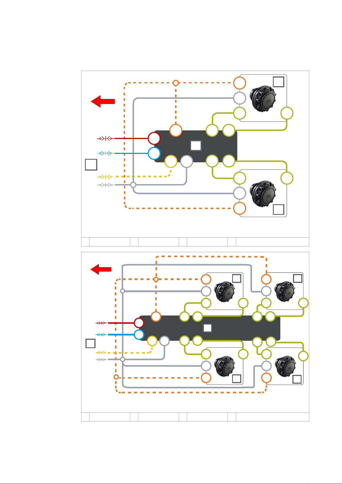
Hydraulic connections
Y
LS
P
C*
Y
A
A
A
B
B
B
T
C
C*
**
***
Y
**
2
3
4
1
Figure 3. Connection diagram, 2WD.
1Valve 2 Motor, right 3 Motor, left 4 Hydraulic lines to the tractor
Y
LS
P
C*
Y
A
A
A
B
B
B
T
C
**
B
2
1
C*
A
2
33
4
**
A
A B
B
C*
**
Y
C*
**
Y
Y
***
Figure 4. Connection diagram, 4WD.
1 Valve 2 Motor, right 3 Motor, left 4 Hydraulic lines to the tractor
* The drain line (C) has a mark (C2) in motors with ushing line (C1).
4.4
System design
14 Product manual

** Make sure that you verify the rotating direction of the left motor from the
datasheet of the motor. Make sure that you connect the left motor correctly. Refer to
the table that follows for the left motor connections.
*** Driving direction.
Table 1: Connections, motor to valve.
Vehicle side Motor type Connections: motor to valve
Right side 1-speed A to A B to B
2-speed, CW preferred A to A B to B
Left side 1-speed A to B B to A
2-speed, CCW preferred A to A B to B
Attention:
The direction of rotation of the right motor must be CW.
Do not use 2-speed motors in the CW direction on the left-hand side.
We recommend that you use a Power Beyond hydraulic interface that connects to a
load sensing pump. If it is not available, connect the lines P and T to the tractor
valves.
Note:
The ow direction is from line P to line T.
Attention:
Do not put together lines C and T.
Always connect the line C to the reservoir without valves.
Table 2: Port sizes.
Port Description CVM120 valve CVU200 valve
P Pump - Working pressure inlet G3/4" G1"
T Tank - Return line G3/4" G1"
C Drain – Case leakage G3/4" G1"
A1, B1, A2, B2 Working lines for the motors G1/2" G3/4"
Y 2-speed function control line G3/8" G3/8"
LS Load-sensing line G1/4" G1/4"
MC, MP, M_A2, M_B2
Measurement points for
C, P, A2, B2 G1/4" G1/4"
Note:
The motor datasheet has the motor port types and the rotating direction.
Selector valve
If you use the same hydraulic supply also to other functions (e.g. crane) with the
drive system, you must usually separate the circuits with a selector valve. An
example of a hydraulic system with a 3/2 selector valve is in the diagram that follows.
In this example the selector valve (1) connects the working pressure (P) line to either
System design
Product manual 15
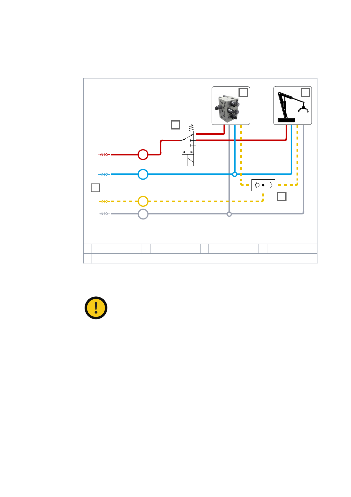
the CVM120/CVU200 valve (2) or to the crane valve (3). If the vehicle has a load-
sensing system, a shuttle valve (4) is also necessary. The shuttle valve lets the
selected valve to control the working pressure level.
LS
P
T
C
4
2
1
3
5
Figure 5. Connection diagram, selector valve.
1 Selector valve 2 CVM120/CVU200 3 Crane valve 4 Shuttle valve
5 Hydraulic lines to the tractor
The CTR101 and CTR201 control systems have an “AUX output” function to control
the external valve from the display. You can use this to control the selector valve. A
maximum permitted current for the valve is 4 A (48 W, 12 V DC)
Attention:
You must connect the pressure inlet port (P) of the CVM120/CVU200 valve
to the de-energized position of the selector valve. The auxiliary valve
output is always de-energized during the driving mode and can energize
only in the freewheeling mode.
You can also use the auxiliary output function for other control purposes in the
maximum current range.
System design
16 Product manual

Port pairs
The port pairs of valve lines A and B have A1/B1 and A2/B2 marks.
Always connect each motor to a port pair as shown in the gure below.
Figure 6. The port pairs.
You can connect left and right side motors to one of the two port pairs.
4.5
System design
Product manual 17

Control system
Model series of the control system
The table that follows shows the dierences between the two control system models,
CTR101 and CTR201.
The CTR201 control system can use the vehicle speed and direction information
through the tractor ISOBUS implement-connector to control the driving functions.
CTR101 CTR201
Connection to tractor ISOBUS implement-connector -●
Drive activation functions:
Automatic, when the tractor starts to move - ●
Automatic, when the system goes back to the
working speed range -●
Manual drive activation ● ●
Automatic drive direction selection (ISOBUS) - ●
Manual drive direction selection ● ● *M)
Tractive power cut-o during braking ● ●
Switching to freewheeling:
Automatic, based on low pressure ● ●
Automatic, based on speed (ISOBUS) - ●
Manual freewheeling ● ●
Shifting between low and high-speed range (2-speed
function):
Manual shift ● ● *M)
Automatic shift - ●
Assisting traction control modes (ATC):
Automatic mode, activation and deactivation
based on speed -●
Activated after forward drive activation for a set
time ●-
Continuous operation ● ●
4WD valve control O O
HDC valve control *) ● ●
Auxiliary valve output function *) ● ●
External alarm input *) ● ●
- = not available, ● = available, O = option
M) Available when you operate the CTR201 in the manual mode.
*) Refer to the “Control system connections” for the necessary cables (see chapters
HDC / AUX valve cable (optional accessory) on page 26, Extension adapter cable for
AUX valve (optional accessory) on page 26 and External alarm input cable (optional
accessory) on page 27).
5
5.1
Control system
18 Product manual

Product identication code
The table that follows gives the identication codes for the model series of the
CTR101 and CTR201 control system.
You can use the identication code to order the control system.
CTR101/CTR201 SERIES MODEL CODE AAAAAA-BB-CCC-DDD-EE-FF
On-Demand Drive control-system series CTR101 and CTR201
AAAAAA: Control
system series
AAAAAA-BB-CCC-DDD-EE-FF CTR101 CTR201
CTR101 ●
CTR201 ●
BB: Conguration AAAAAA-BB-CCC-DDD-EE-FF CTR101 CTR201
2WD A1 : Single controller for 2WD ● ●
4WD A2 : Dual controller for 4WD ● ●
CCC: Software AAAAAA-BB-CCC-DDD-EE-FF CTR101 CTR201
B00 : Standard software for CTR101 ●
C00 : Standard software for CTR201 ●
DDD: Supply kit AAAAAA-BB-CCC-DDD-EE-FF CTR101 CTR201
I10 : 10 m power / ISOBUS cable
with ISOBUS implement connector
and terminating bias circuit
●
P10 : 10 m power cable with free +/-
leads ●
EE: Options 1 AAAAAA-BB-CCC-DDD-EE-FF CTR101 CTR201
H0 : default / not dened ● ●
FF: Options 2 AAAAAA-BB-CCC-DDD-EE-FF CTR101 CTR201
C0 : default / not dened ● ●
Control system connections
Important notes
When you plan to use the CTR101/CTR201 control system, make sure that:
• The nominal operating voltage of the control system is 12 V. Do not connect the
system to a dierent voltage.
• The current requirement of the power supply of the system is 15 A. Make sure that
you always use a connection with a fuse.
• When the control device has no power, the system switches the motors to
freewheeling. Make sure that you can switch o the power supply to the control
device from the tractor's cab.
5.2
5.3
5.3.1
Control system
Product manual 19
• Attach the control device near the valve and in a location where the mechanical
shocks or wear cannot cause damage to it. If necessary, use mechanical
protection.
• Make sure that the installation location of the cables:
• Does not cause too much force on the cables
• Is not abrasive
• Does not let the cables catch between the moving parts of the machine and
break them.
• The system components are classied as water-resistant, but do not put the
components fully into water.
• Install the display in the tractor cab. Use the mounting set that is supplied with
the display. It includes a mounting frame and a pivot arm.
• You must start the control device again if the display cable disconnects and you
connect it when the control system power is on. Switch the power o and on
again.
•CTR201: Make sure that the tractor obeys the ISOBUS class 2 requirements. The
automatic drive control mode will not operate correctly with an ISOBUS class 1
tractor.
•CTR201: Always use the ISOBUS implement connector (IBBC) when you connect
the system to the tractor.
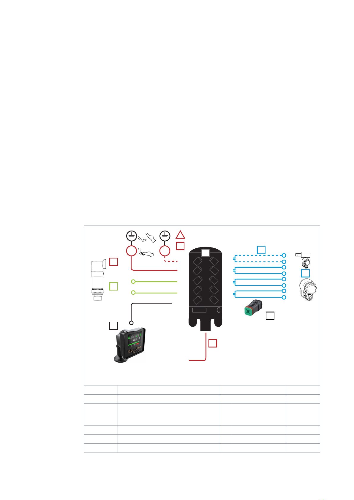
Control system connection diagrams
8
6
4
2
CAN OUT
7
5
3
1
CAN IN
6
3
2
WV1
P_A
WV3
M_B
M_A
PDB
+12V
12 V DC
WV2
2
1 PDB2
P_B
1
4
+12V
5
89
7
!
AUX
Figure 7. Connection diagram, 2WD.
1 Control device
Cables Description Cable ID Length [m]
2 Valve cables
WV1 / P_A
WV3 / P_B
PDB / WV2
1
3 Brake signal cable Brake_sig 10
4 Pressure sensor cables M_A, M_B 1
5 Display cable + extension Display 10 + 0.3
5.3.2
Control system
20 Product manual
This manual suits for next models
4
Table of contents
Other Black Bruin Control System manuals

Popular Control System manuals by other brands

Velleman
Velleman CAMSET24 user manual

Duro Dyne
Duro Dyne DuroZone RED-4 installation instructions

Medem
Medem SEC-Le V4 installation instructions

PAW
PAW HeatBloC K33R Installation and operation instruction

Contro l4
Contro l4 Control4 Smart Home quick start guide

Force America
Force America SSC6100 CAN ULTRA Operation manual


