Translation of the original instructions
© 2020 all rights reserved to Festo SE & Co. KG
1 About this document
This document describes the use of the above-mentioned product family.
Certain aspects of use are described in other documents and must be observed
è 1.1 Applicable Documents.
1.1 Applicable Documents
All available documents for the product èwww.festo.com/pk.
Document Contents
Description of the automation system CPX-E
(CPX-E-SYS)
Detailed description of the
automation system CPX-E
Documentation of the components in an
automation system CPX-E and the connected
peripherals
Information on using the components
Operating conditions EX Information on the use of the product in poten-
tially explosive gas atmospheres
Device description files Definition of the modules of an
automation system CPX-E for integration into the
higher-order controller
Documentation for the higher-order controller
and the additional participants in the network
Information on commissioning and paramet-
erisation of the components
Tab. 1 Applicable Documents
1.2 Product version
This document refers to the automation system CPX-E with CPX-E modules.
The product version can be identified from the product labelling or with the help
of appropriate software from Festo.
Appropriate software for determining the product version can be found in the
Festo Support Portal èwww.festo.com/sp.
Information on using the software can be found in the integrated Help function.
1.3 Product labelling
The CPX-E modules are labelled on the left lateral surface. The product labelling is
described in the documentation supplied with the product.
1.4 Specified standards
Version status
DIN46228-1:1992-08 EN60529:2013-10
DIN46228-4:1990-09 EN60715:2001-09
EN60068-2-27:2010-02 IEC60204-1:2014-10
Tab. 2 Standards specified in the document
1.5 UL/CSA Certification
In combination with the UL inspection mark on the product, the information in this
section must also be observed in order to comply with the certification conditions
of Underwriters Laboratories Inc. (UL) for USA and Canada.
UL certification information
Product category code NRAQ/NRAQ7
File number E239998
UL certification information
Considered standards UL 61010-1, 3rd Edition, May 11, 2012, revised April 29, 2016
CAN/CSA-C22.2 No. 61010-1-12, 3rd Edition, revision dated April
29, 2016
UL 61010-2-201, 1st Edition, revised February 20, 2017
CSA-C22.2 No. 61010-2-201: 14, 1st Edition, issue date January
01, 2014
UL mark
Tab. 3 UL/CSA Certification Information
– Technical data and environmental conditions may be subject to change in
order to comply with Underwriters Laboratories Inc. (UL) certification require-
ments for the USA and Canada.
Observe deviations èTechnical data.
– The unit shall be supplied by a power source which fulfils the requirements
on a limited-energy circuit in accordance to IEC/EN/UL/CSA 61010-1 or on a
Limited Power Source (LPS) in accordance to IEC/EN/UL/CSA 60950-1 or
IEC/EN/UL/CSA 62368-1 or a Class 2 circuit in accordance to NEC or CEC.
Unauthorised access to the device can cause damage or malfunctions.
When connecting the device to a network:
Protect the network against unauthorised access.
Measures to protect the network include:
• Firewall
• Intrusion Prevention System (IPS)
• Network segmentation
• Virtual LAN (VLAN)
• Virtual private Network (VPN)
• Security at physical access level (port security)
For additional information èGuidelines and standards for security in information
technology, e.g. IEC62443, ISO/IEC27001.
An access password only protects against unintentional modification.
NOTICE!
Modules with Ethernet interfaces should only be operated in networks if all con-
nected network components are supplied by PELV circuits or integrated circuits
with equivalent protection.
2 Safety
2.1 Safety instructions
– Take into consideration the legal regulations for the respective destination.
– Use the product only within the defined values è 15 Technical data.
– Observe labelling on the product.
– Observe further applicable documents.
– Store the product in a cool, dry, UV-protected and corrosion-protected envir-
onment. Ensure that storage times are kept to a minimum.
– Before working on the product: switch off the power supply and secure it
against being switched on again.
– Comply with the handling specifications for electrostatically sensitive devices.
2.2 Intended Use
The product described in this document is intended only for use within a protec-
ted range in the vicinity of a machine and/or automated system.
Use the product only as follows:
– Use only in an industrial environment. Outside industrial environments,
e.g.in commercial and residential/mixed-use areas, it may be necessary to
take measures to suppress radio interference.
– Use only in combination with modules and components that are permissible
for the respective product variant èwww.festo.com/catalogue.
– Only use the product if it is in perfect technical condition.
– Only use the product in original status without unauthorised modifications.
Only the conversions or modifications described in this and the further applic-
able documents are permitted.
2.3 Training of Qualified Personnel
Installation, commissioning, maintenance and disassembly should only be con-
ducted by qualified personnel. The qualified personnel must be familiar with
installation of electrical control systems.
3 Further information
– Accessories èwww.festo.com/catalogue.
– Spare parts èwww.festo.com/spareparts.
4 Service
Contact your regional Festo contact person if you have technical questions
èwww.festo.com.
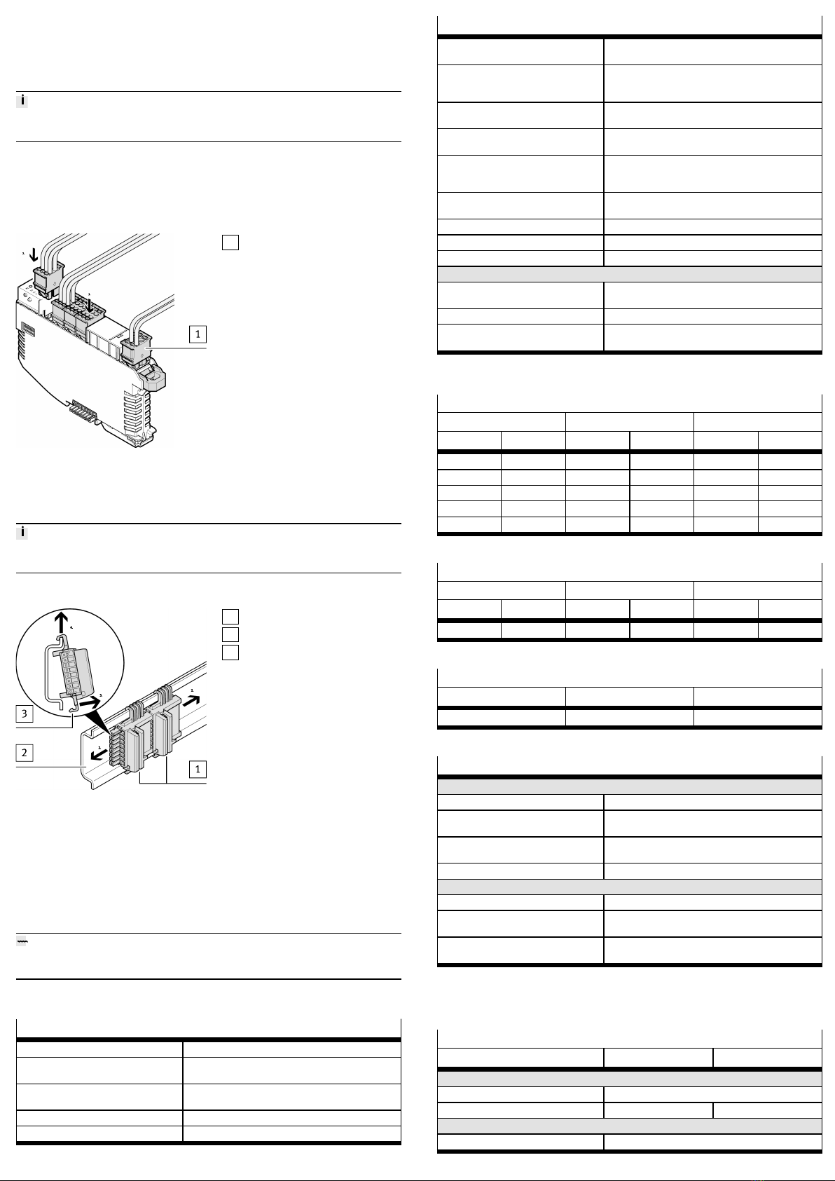
5 Product overview
5.1 Function
The Automation system CPX-E is a modular system for the connection of electrical
peripherals. The individual modules in an Automation system CPX-E are used,
8126712
CPX-E
Automation system
8126712
2020-01a
[8126714]
Instructions| Operating
Festo SE & Co. KG
Ruiter Straße 82
73734 Esslingen
Germany
+49 711 347-0
www.festo.com