Black Bruin B240 User manual
Product Manual
B200 series

Contents
1 General Instructions......................................................................... 4
1.1 About the manual............................................................................................................................................4
1.2 Intended use.....................................................................................................................................................4
1.3 Warranty.............................................................................................................................................................4
1.4 Product identication..................................................................................................................................... 4
1.5 Revision comments.........................................................................................................................................4
1.6 Declaration of incorporation......................................................................................................................... 5
2 Safety Instructions........................................................................... 6
2.1 Warning symbols..............................................................................................................................................6
3 Motor Description.............................................................................. 7
3.1 Working principle.............................................................................................................................................. 7
3.2 Product identication code...........................................................................................................................8
3.2.1 Motor model code......................................................................................................................... 8
3.2.2 Processing ID................................................................................................................................. 9
3.3 Technical data.................................................................................................................................................10
3.4 Motor interfaces............................................................................................................................................. 12
3.4.1 Main dimensions..........................................................................................................................12
3.4.2 Shaft interface............................................................................................................................. 13
3.4.3 Hub interface................................................................................................................................14
3.4.4 Housing interface........................................................................................................................15
3.4.5 Drum brake interface.................................................................................................................. 17
3.5 Rotating direction.......................................................................................................................................... 18
3.6 Mechanical freewheeling............................................................................................................................. 19
3.7 1-speed : 1N00............................................................................................................................................... 20
3.8 2-speed valve : 2N0R / 2N0L......................................................................................................................21
3.9 Freewheeling valve : FW10 / FW20........................................................................................................... 22
3.10 Seal protector : NZ/GZ................................................................................................................................. 24
3.10.1 Fittings for one-time lubrication.............................................................................................24
3.10.2 Fittings for regular lubrication.................................................................................................24
4 System Design................................................................................. 26
4.1 Motor hydraulic circuit................................................................................................................................. 26
4.1.1 Simple connection......................................................................................................................26
4.1.2 Motors in parallel or series circuit...........................................................................................26
4.1.3 Counter pressure operation.....................................................................................................28
4.1.4 Hydrostatic braking....................................................................................................................28
4.1.5 Short circuit operation...............................................................................................................28
4.2 Hydraulic connections................................................................................................................................. 29
4.3 External freewheeling valve....................................................................................................................... 29
4.4 Hydraulic uid................................................................................................................................................. 31
4.4.1 Hydraulic uid type..................................................................................................................... 31
4.4.2 Hydraulic uid properties.......................................................................................................... 31
4.4.3 Hydraulic uid cleanliness.........................................................................................................31
4.5 Operating pressures...................................................................................................................................... 31
4.5.1 Case pressure...............................................................................................................................31
4.5.2 Pilot pressure............................................................................................................................... 32
4.5.3 Working line pressure.................................................................................................................32
Contents
2 Product Manual

5 Motor Sizing..................................................................................... 34
5.1 Load carrying capacity................................................................................................................................ 34
5.1.1 Wheel oset..................................................................................................................................34
5.1.2 Allowed wheel load.....................................................................................................................35
5.1.3 Service life.................................................................................................................................... 35
5.2 Performance...................................................................................................................................................36
5.2.1 Rotating speed and ow rate.................................................................................................. 36
5.2.2 Torque............................................................................................................................................ 37
5.2.3 Power.............................................................................................................................................38
6 Installation Instructions................................................................ 39
6.1 Mounting the motor......................................................................................................................................39
6.2 Flushing the hydraulic system...................................................................................................................39
6.3 Air bleeding procedure.................................................................................................................................39
6.4 Commissioning procedure..........................................................................................................................40
7 Operating Instructions................................................................... 41
7.1 Break-in period............................................................................................................................................... 41
7.2 Use..................................................................................................................................................................... 41
7.3 Operating temperature.................................................................................................................................41
7.4 Demounting the motor.................................................................................................................................41
8 Special Instructions........................................................................43
8.1 Storing the motor..........................................................................................................................................43
Contents
Product Manual 3

General Instructions
About the manual
This manual contains the technical instructions for the Black Bruin B200 series
hydraulic motors. Take these instructions into consideration when planning the use
of the product.
All information given in this manual is current and valid according to the information
available at the time of publication. The manufacturer reserves the rights to
implement changes without prior notice.
Please visit www.blackbruin.com for the most recent version of this manual. The
product datasheets and the 3D-models are available from the manufacturer by
request.
Intended use
Black Bruin B200 series hydraulic motors are designed to be used as hub motors to
produce traction on tractor-driven trailers and working equipment.
Warranty
Check the package and the product for transport damage when receiving goods. The
package is not meant for long term storage; protect the product appropriately.
Do not dismantle the product. The warranty is void if the product has been
disassembled.
The manufacturer is not responsible for damages resulting from misinterpreted, non-
compliance, incorrect, or improper use of the product that goes against the
instructions given in this document.
Product identication
The product identication data can be found on the identication plate attached to
the motor.
Figure 1. Identication plate of the motor.
1. Serial number
2. Part number
3. Model
4. Maximum allowed operating pressure
Note:
The serial number is also stamped on the motor. All manufacturing data
can be found with the serial number.
Revision comments
24.08.2018 - This manual is published.
1
1.1
1.2
1.3
1.4
1.5
General Instructions
4 Product Manual

Declaration of incorporation1.6
General Instructions
Product Manual 5

Safety Instructions
The following instructions apply to all procedures associated with the motor. Read
these instructions carefully and follow them closely.
• Use necessary personal protective equipment when working with the motor.
• Support the motor properly. Make sure the motor cannot fall over or turn around
by accident.
• Use only appropriate equipment and attachments for lifting and transferring the
motor.
• Do not use magnetic lifting devices.
• Always use the lifting equipment properly and check the load-bearing capacity.
• Prevent unintended use of the motor during installation and maintenance
procedures by preventing pressurization of the hydraulic lines.
• The operating temperature of the motor may be over 60 ºC (140 °F), which is hot
enough to cause severe burns. Beware of hot hydraulic uid when disconnecting
the hydraulic connections.
Warning symbols
The following symbols are used in this manual:
Note:
Useful information.
Danger:
Danger of death or injury.
Attention:
May cause damage to the product.
2
2.1
Safety Instructions
6 Product Manual
Motor Description
Working principle
B200 series motors are rotary-housing. This means the motor shaft and the cylinder
block remain in place while the motor is running.
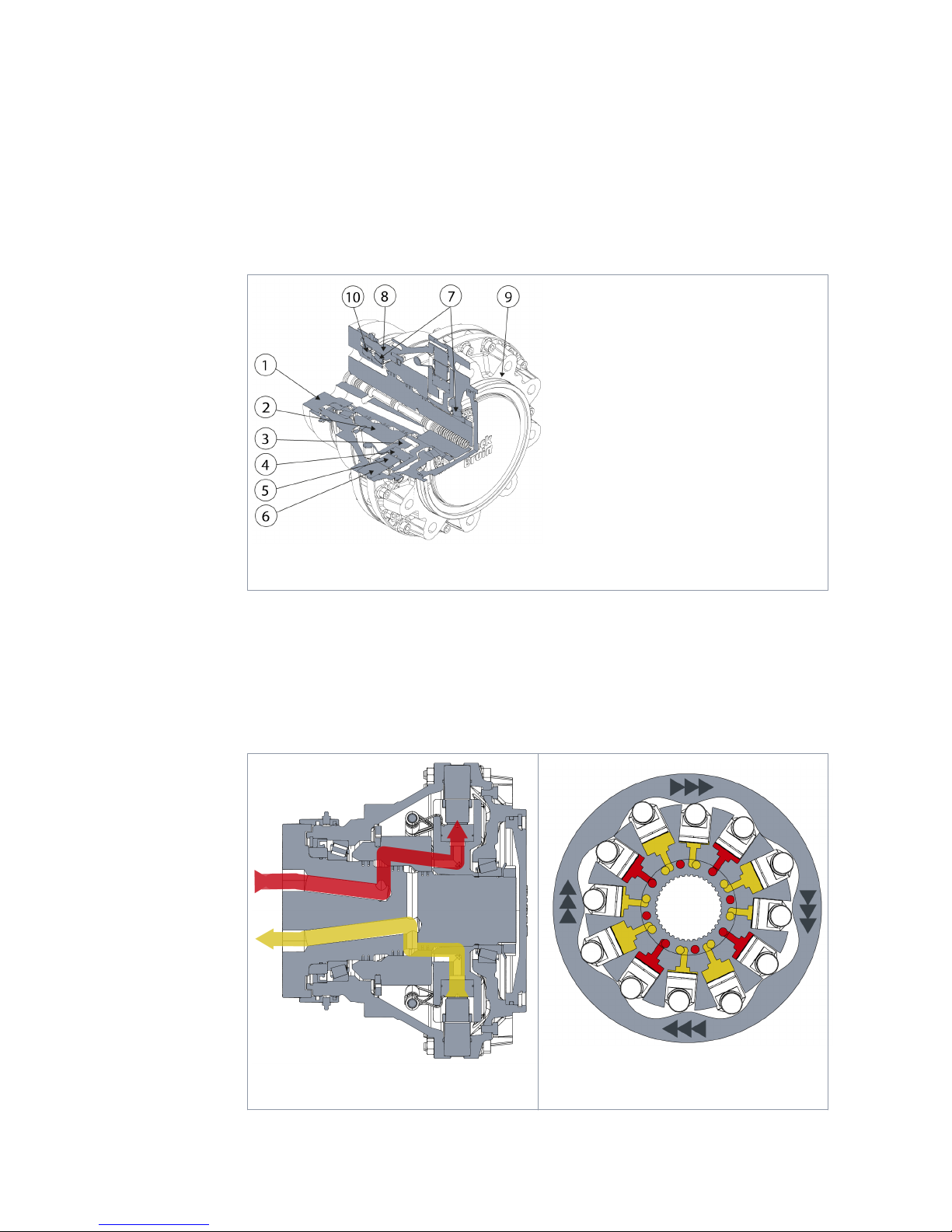
Figure 2. The main components of the motor.
1. Shaft
2. Distribution valve
3. Cylinder block
4. Piston
5. Cam roll
6. Cam ring
7. Bearings
8. Housing
9. Hub
10. Shaft sealing
The rotation of the motor is achieved by feeding pressurized hydraulic uid through
the motor shaft to the distribution valve. The distribution valve directs the ow to the
pistons which are on a power stroke. Pressure pushes the pistons and cam rolls
outwards against the cam ring on the housing. The waveform of the cam ring
transforms the force into torque. When the pistons reach the end of the power stroke,
the distribution valve closes the ow to the pistons and switches the pistons to a
return stroke.The cam ring pushes the pistons back into the cylinder block preparing
them for the next outward power stroke.
Figure 3. Flow to the pistons.
Figure 4. Cylinder block, cam ring and pis-
tons.
3
3.1
Motor Description
Product Manual 7

Product identication code
Black Bruin product identication code consists of motor model code and processing
ID.
B260-0250-2NOL / GZ -1 1 0 0 0 0
Motor model code - Processing ID
Motor model code
B200 SERIES MODEL CODE AAAA - BBBB - CCCC / D
Freewheeling hub motors
A: Frame AAAA-BBBB-CCCC/D B240 B250 B260 B270
B200 series frames
B240 ●
B250 ●
B260 ●
B270 ●
B: Displacement AAAA-BBBB-CCCC/D B240 B250 B260 B270
B240 displacements 0063 : 630 ccm/rev ●
0080 : 800 ccm/rev ●
B250 displacements
0100 : 1000 ccm/rev ●
0125 : 1250 ccm/rev ●
0160 : 1600 ccm/rev ●
B260 displacements
0200 : 2000 ccm/rev ●
0250 : 2500 ccm/rev ●
0315 : 3150 ccm/rev ●
B270 displacements
0400 : 4000 ccm/rev ●
0500 : 5000 ccm/rev ●
0630 : 6300 ccm/rev ●
C: Displacement control AAAA-BBBB-CCCC/D B240 B250 B260 B270
1-speed 1N00 : Fixed displacement ●●●●
2-speed valve 2N0R : Right side - CW preferred ●●●●
2N0L : Left side - CCW preferred ●●●●
Freewheeling valve
FW10 : Type 1 - Open freewheel-
ing position ●●●
FW20 : Type 2 - Closed free-
wheeling position ●●●
D: Accessory AAAA-BBBB-CCCC/D B240 B250 B260 B270
No drum brake
NZ : Fittings for one-time lubri-
cation ● ● ● ●
GZ : Fittings for regular lubrica-
tion ● ● ● ●
3.2
3.2.1
Motor Description
8 Product Manual
D: Accessory AAAA-BBBB-CCCC/D B240 B250 B260 B270
Drum brake*
MRJ40-0 : Brake size 320x75 ●
MRJ50-0 : Brake size 400x80 ●
MRJ60-R : Brake size 420x220 -
Right side ●
MRJ60-L : Brake size 420x220 -
Left side ●
* = Certied brakes, manufactured by Monroc.
More detailed information and mounting dimensions for each brake device can be found
on the product datasheet.
The drum brake increases the length of the motor assembly and aects the oset value of
the vehicle wheel rim.
Adding lubricant into the seal protector is prevented.
Code example B260 - 0250 - 2N0L / GZ
A - B - C / D
A = The frame of the motor is "B260"
B = The displacement of the motor is 2500 ccm/rev
C = Internal 2-speed valve for displacement control. The motor is CCW preferred in 2-
speed mode.
D = The seal protector of the motor is tted for regular lubrication
Processing ID
B200 SERIES PROCESSING ID R M S P D T
R M S P D T Lubrication Denition of factory lubrication
0 = Seal protector is not lled with lubricant. 1)
1 = Seal protector is lled with lubricant.
R M S P D T Painting Denition of the painted surfaces
0 = No painting - Motors are washed and protected from corrosion.
1 = Painting type 1 - Unpainted interfaces: SHAFT, HUB 2)
2 = Painting type 2 - Unpainted interfaces: SHAFT, HUB, HOUSING 2)
R M S P D T Protection Denition of the protection for storage/trans-
portation
0 = Default / Not dened 3)
R M S P D T Packaging Denition of the motor package
0 = Default / Not dened 4)
R M S P D T Documents Denition of the printouts to be attached to the
delivery
0 = Default / Not dened
3.2.2
Motor Description
Product Manual 9

R M S P D T Testing Denition of the testing and reporting
0 = Default / Not dened 5)
Code example 1 1 0 0 0 0
R M S P D T
R = The seal protector of the motor is lled with lubricant.
M = Prime coating. The shaft and hub interfaces of the motor are unpainted.
S = Pressure openings and threaded holes of the motor are protected according to
general practices of the manufacturer.
P = The motor is packaged according to general practices of the manufacturer.
D = The documentation delivered with the motor is according to general practices of
the manufacturer.
T = The motor is tested according to general practices of the manufacturer.
1) If necessary, the seal protector is not lled with lubricant at the factory.
2) Prime coating: HEMPATHANE HS 55610 or equivalent. Tint: glossy black.
3) Pressure openings and threaded holes are capped with plastic ttings. Hydraulic
uid is drained out.
4) Delivery on wooden pellet or in plywood box.
5) The manufacturer keeps test records of every manufactured motor.
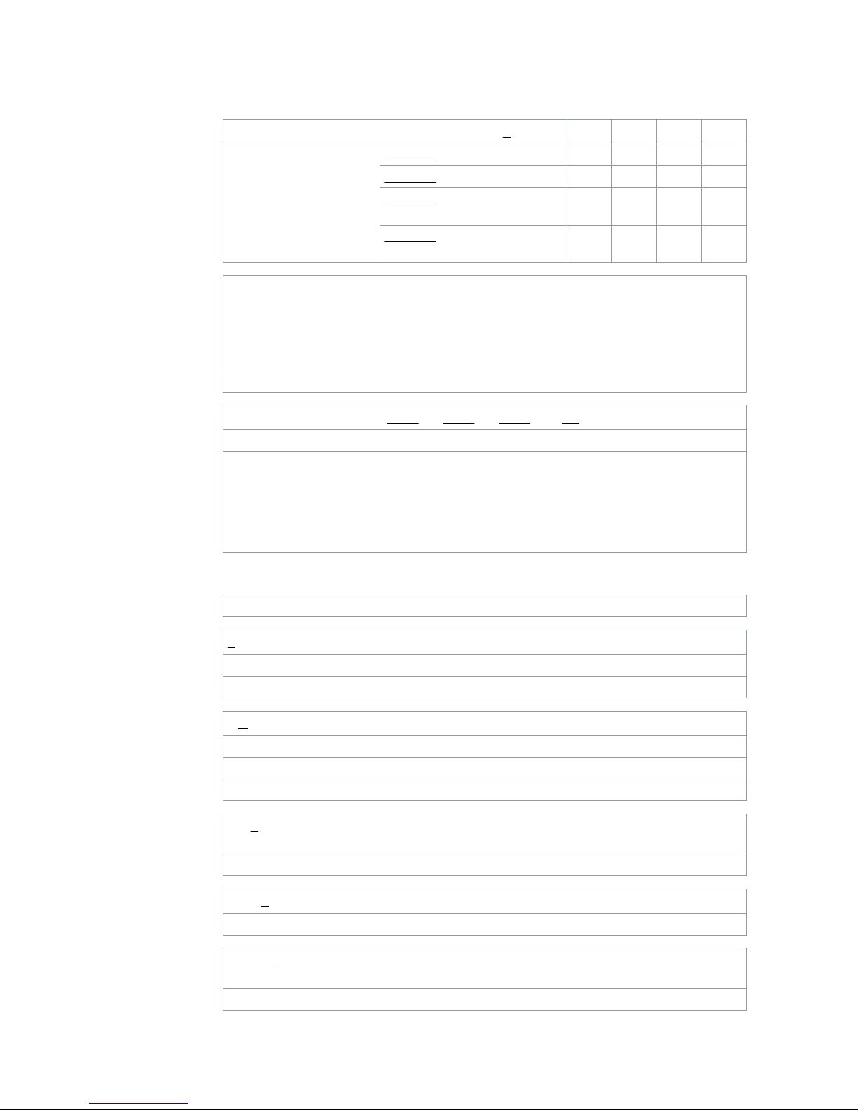
Technical data
TECHNICAL DATA B240 B250
Displacement [ccm]
at full displacement 630 800 1000 1250 1600
at half displacement 315 400 500 625 800
Maximum torque [Nm]
theoretical 3510 4460 5570 6960 8910
with 100 bar 1000 1270 1590 1990 2550
Max. operating power [kW]
at full displacement 35 50
at half displacement 21 30
Max. rotating speed [rpm]
at full displacement 240 185 200 160 125
at half displacement 360 275 300 240 185
at freewheeling 600 500
Min. rotating speed [rpm] 2 2
Max. engaging speed (out of freewheel-
ing) [rpm] 120 93 100 80 63
Brake torque [Nm] 1) 8600 13500
Max. working pressure [bar]
peak pressure 350 350
intermittent 2) 300 300
Max. case pressure [bar]
3.3
Motor Description
10 Product Manual

TECHNICAL DATA B240 B250
average 2 2
intermittent 2) 10 10
Pilot pressure for internal valve [bar]
valve released 0-2 0-2
valve engaged 15-30 3) 15-30 3)
Max. ow rate [l/min]
at full displacement 150 200
at half displacement 113 150
Max. load capacity [t] 4) 4,0 5,4
Weight [kg] no brake 59 92
with drum brake 96 156
TECHNICAL DATA B260 B270
Displacement [ccm]
at full displacement 2000 2500 3150 4000 5000 6300
at half displacement 1000 1250 1575 2000 2500 3150
Maximum torque [Nm]
theoretical 14300 17900 22600 28600 35800 45100
with 100 bar 3180 3980 5010 6370 7960 10000
Max. operating power [kW]
at full displacement 90 130
at half displacement 54 80
Max. rotating speed [rpm]
at full displacement 175 140 110 125 100 80
at half displacement 225 180 145 160 130 105
at freewheeling 400 350
Min. rotating speed [rpm] 2 2
Max. engaging speed (out of freewheel-
ing) [rpm] 88 70 55 63 35 40
Brake torque [Nm] 1) 20100 -
Max. working pressure [bar]
peak pressure 450 450
intermittent 2) 400 400
Max. case pressure [bar]
average 2 2
intermittent 2) 10 10
Pilot pressure for internal valve [bar]
valve released 0-2 0-2
valve engaged 15-30 3) 15-30 3)
Max. ow rate [l/min]
Motor Description
Product Manual 11
TECHNICAL DATA B260 B270
at full displacement 350 500
at half displacement 225 325
Max. load capacity [t] 4) 12,5 15,4
Weight [kg] no brake 150 285
with drum brake 262 -
1) The braking torque is for information only. Braking performance should be
ensured by testing and / or certication.
2) Intermittent operation: permissible values for maximum of 10% of every minute.
3) If pilot pressure over 30 bar is used, the pilot line should be throttled.
4) The load capacity must be estimated for every application.
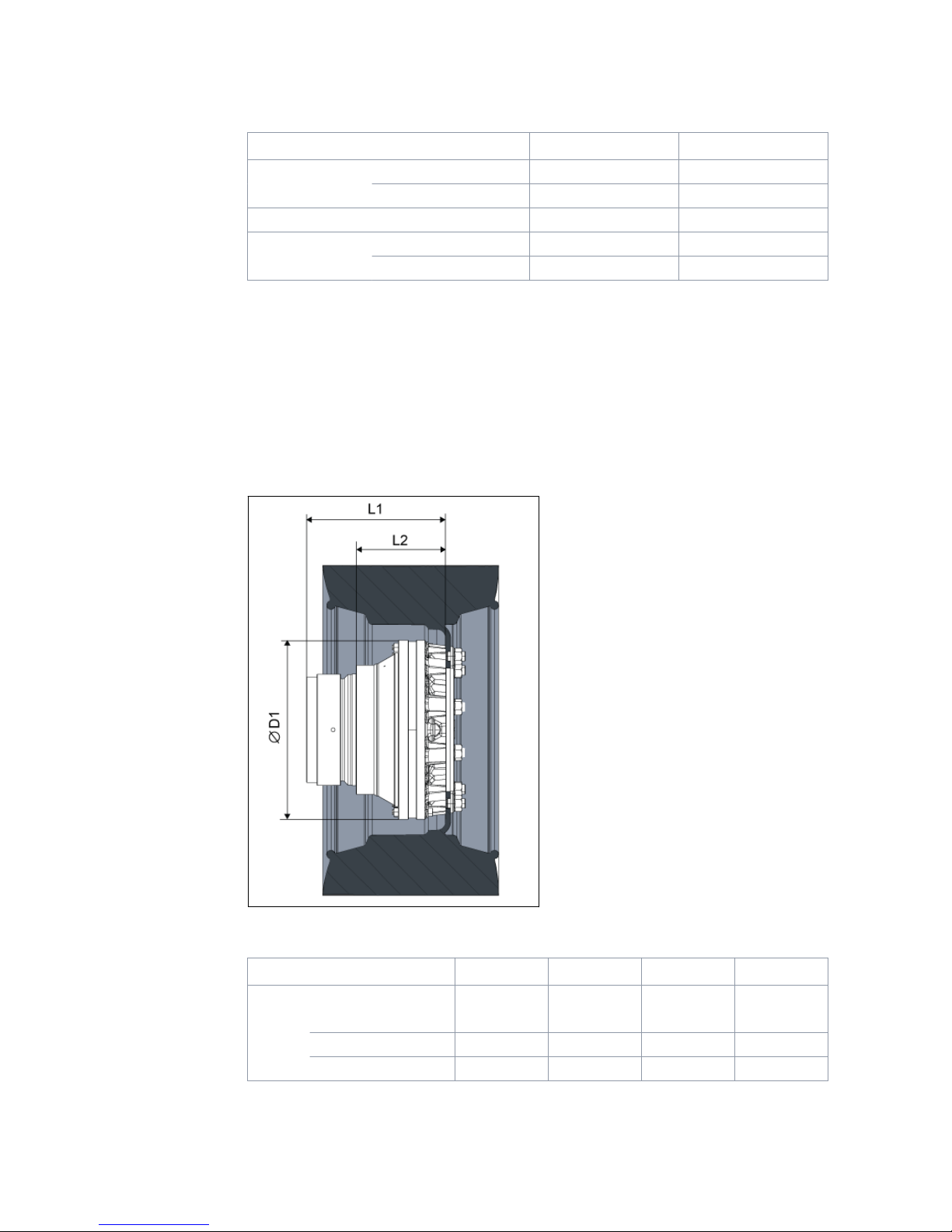
Motor interfaces
Main dimensions
Figure 5. Main dimensions of the motor.
MAIN DIMENSIONS B240 B250 B260 B270
Motor
L1 [mm] 262 279 317 377
L2 [mm] 163 177 204 262
D1 [mm] 278 342 408 512
3.4
3.4.1
Motor Description
12 Product Manual
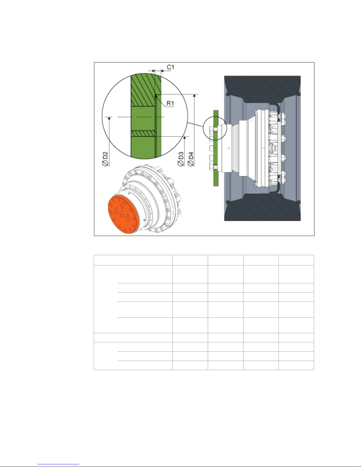
Shaft interface
Figure 6. Dimensions of the shaft interface.
INTERFACE DIMENSIONS B240 B250 B260 B270
Shaft interface
D2 [mm] 140 175 200 260
pattern 6x60° 8x45° 12x30° 16x22,5°
size M16x2,0 M16x2,0 M20x1,5 M20x1,5
strength class
1) 12,9 12,9 12,9 12,9
tightening tor-
que 2) [Nm] 330 330 650 650
D3 min. 3) [mm] 114 150 170 220
D4 min. 4) [mm] 165 200 240 300
R1 max. [mm] 1 1 1 1
C1 [mm] 4-10 4-10 4-10 4-10
1) Strength class as in ISO898-1. If using lower strength class, check interface load
capacity and tightening torque.
2) Declared values are for reference only. Always use application specic
tightening torques when given.
3) Free space for hydraulic connections.
4) Recommended feature to support and center the motor.
3.4.2
Motor Description
Product Manual 13

The motor is attached to the body of the vehicle or device from the shaft ange. The
hydraulic connections of the motor are located on the plane surface of the shaft
ange.
Hub interface
Figure 7. Dimensions of the hub interface.
INTERFACE DIMENSIONS B240 B250 B260 B270
Hub interface
D5 [mm] 205 275 335 425
pattern 6x60° 8x45° 10x36° 12x30°
size M18x1,5 M20x1,5 M22x1,5 M22x1,5
strength class
1) 10,9 10,9 10,9 10,9
tightening tor-
que 2) [Nm] 383 540 728 728
D6 min. [mm] 161 221 281 381
V1 min. [mm] 1x45° 1x45° 1x45° 1x45°
D7 min. [mm] 255 325 390 470
1) Strength class as in ISO898-1. If using lower strength class, check interface load
capacity and tightening torque.
3.4.3
Motor Description
14 Product Manual

2) Declared values are for reference only. Always use application specic
tightening torques when given.
The wheel rim or the rotatable device is attached to the motor hub.
Note:
The attachment screws are not included in the motor delivery. Ensure
correct dimensioning and availability of the hub screws.
There are multiple dierent type of fastening screws for hub interface.
Select the hub screws according to the wheel rim design.
Figure 8. Hub fastening screw variants.
Housing interface
Figure 9. Dimensions of the housing interface.
3.4.4
Motor Description
Product Manual 15
INTERFACE DIMENSIONS B240 B250 B260 B270
Housing interface
D8 [mm] 204 236 274 330
pattern 12x30° 12x30° 18x20° 18x20°
size M10x1,5 M12x1,75 M12x1,75 M16x2,0
strength class1) 10,9 10,9 10,9 10,9
tightening tor-
que 2) [Nm] 64 110 110 275
D9 min. [mm] 184 205 254 302
V2 min. [mm] 1x45° 1x45° 1x45° 1x45°
1) Strength class as in ISO898-1. If using lower strength class, check interface load
capacity and tightening torque.
2) Declared values are for reference only. Always use application specic
tightening torques when given.
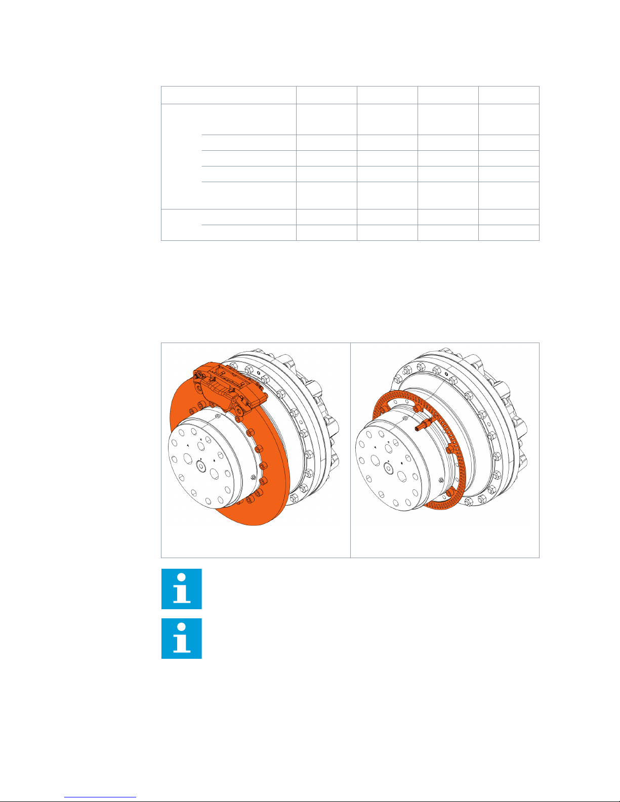
The necessary accessories can be attached to the housing interface. The interface
can be used, for example, to attach a brake disc of a disc brake or a speed sensor
pulse ring.
Figure 10. The motor with a disc brake. Figure 11. The motor with a pulse sensor.
Note:
If necessary, the grease nipples and plugs of the seal protector can be
removed temporarily when attaching accessories to the housing interface.
Note:
Surface roughness (Ra) of the counterparts must be 12,5μm or better.
More detailed interface dimensions and tolerances are indicated on the
product datasheet.
Motor Description
16 Product Manual

Drum brake interface
Figure 12. Interface dimensions of the motor with the drum brake (B240, B250).
Figure 13. Interface dimensions of the motor with the drum brake (B260).
INTERFACE DIMENSIONS B240 B250 B260
Drum brake interface
L3 [mm] 277 295 451
D10 [mm] 349 444 460
D11 [mm] 140 175 200
pattern 6x60° 8x45° 12x30°
size M16x2,0 M16x2,0 M20x1,5
strength class
1) 12,9 12,9 12,9
3.4.5
Motor Description
Product Manual 17

INTERFACE DIMENSIONS B240 B250 B260
tightening tor-
que 2) [Nm] 330 330 650
D12 [mm] max. 121 max. 156 min. 235,5
C2 [mm] 4,5 4,5 4,5
V3 min. [mm] 1x45° 1x45° 1x45°
R2 max. [mm] 1 1 1
D13 [mm] 114 150 170
1) Strength class as in ISO898-1. If using lower strength class, check interface load
capacity and tightening torque.
2) Declared values are for reference only. Always use application specic
tightening torques when given.
Rotating direction
Figure 14. Rotating direction of the motor.
The rotating direction of the motor is dened as the rotating direction of the housing
viewed from the hub to the shaft.
The rotating direction of the motor and the ow direction in the working lines is given
in the table below.
Table 1: Rotating direction and ow direction.
ROTATING DIRECTION ow direction
A → B B → A
1N00, FW10, FW20 CW CCW
2N0R CW CCW
2N0L CCW CW
Preferred operating direction
AAAA - BBBB - 2N0R / D
AAAA - BBBB - 2N0L / D
3.5
Motor Description
18 Product Manual
The preferred operating direction applies to motors with 2-speed valve (see 2-speed
valve : 2N0R / 2N0L on page 21).
The preferred operating direction is the rotating direction of the motor when the ow
direction is from port A to B.
•2N0R = CW motor (For the right side of a vehicle.)
•2N0L = CCW motor (For the left side of a vehicle.)
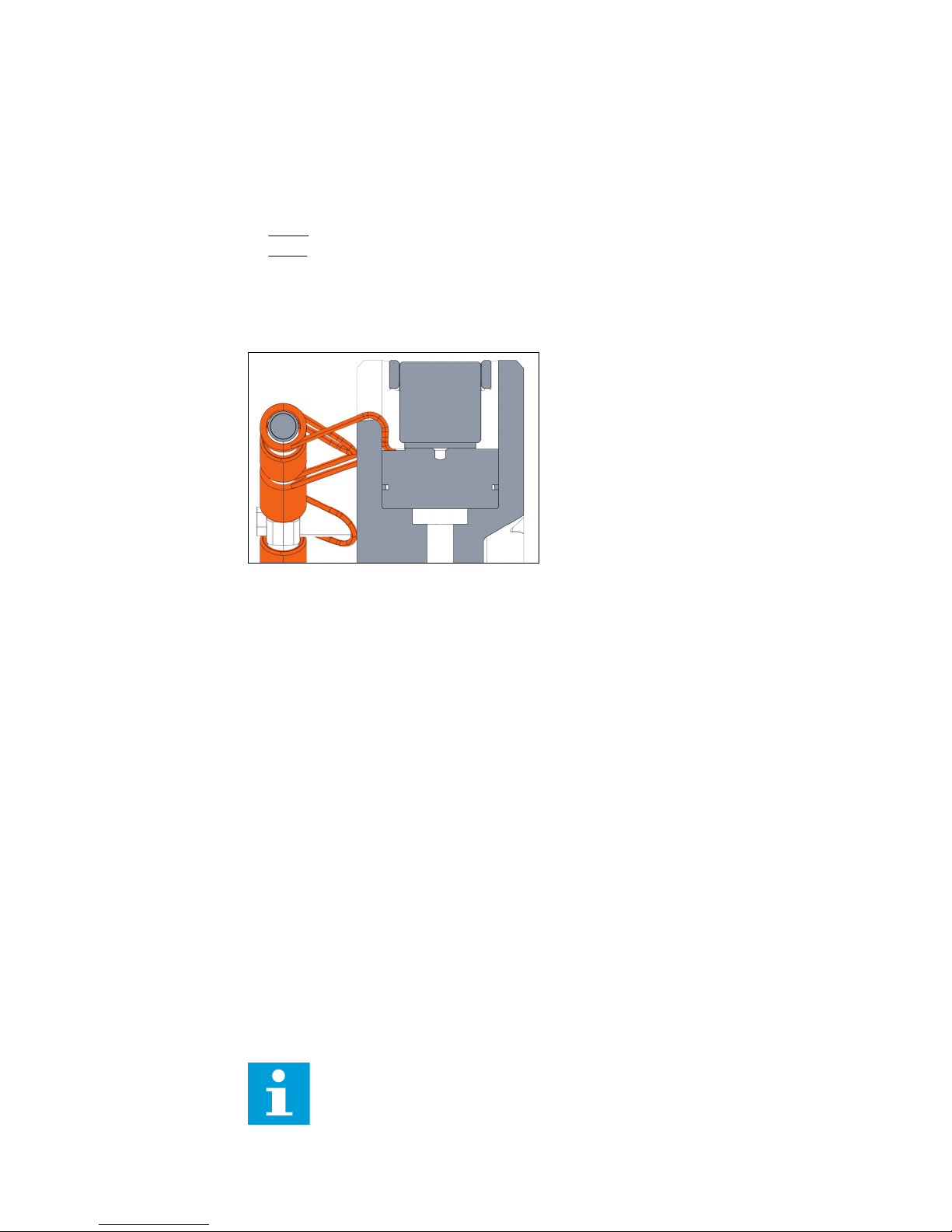
Mechanical freewheeling
The mechanical freewheeling is a standard feature in the B200 series motors.
Figure 15. A piston with the freewheeling spring.
The motor is equipped with mechanical freewheeling springs, which enable the motor
disengagement. When disengaged the motor may be used without active uid supply
from the hydraulic system.
USING THE FREEWHEELING
When the motor is depressurized and not rotating, the motor will disengage
automatically. The motor disengagement during motion is done with a freewheeling
valve.
The freewheeling valve may be in-built to the motor (see Freewheeling valve : FW10 /
FW20 on page 22) or a separate external valve (see External freewheeling valve on
page 29), which connects the working lines (A and B) and the case drain line (C)
together. The purpose of the valve is to remove pressure dierence over the motor
pistons. This allows the pistons to retract with aid of mechanical springs.
• DISENGAGING THE MOTOR
Open the freewheeling valve and depressurize the motor with the directional
control valve to disengage the motor.
• ENGAGING THE MOTOR
Close the freewheeling valve and pressurize the motor with the directional control
valve to engage the motor.
The directional control valve and the freewheeling valve are usually activated
simultaneously.
Note:
Another use of the freewheeling is a more extensive speed range for
vehicles having several hydraulic motors. Hydraulic system capacity may
3.6
Motor Description
Product Manual 19

be divided between fewer motors, when some of the motors are
disengaged.
Attention:
Any pressure in the working lines (A and B) during the freewheeling
pushes the pistons out of the freewheeling position. This causes clattering
noise when the pistons connect to the cam ring.
Constant clattering of the pistons may cause premature wear or failure of
the motor.
ROTATING SPEED
The rotating speed of the motor should be taken into account when implementing
freewheeling.
• FREEWHEELING SPEED
The freewheeling speed is the highest permissible rotating speed of the motor
during freewheeling.
• ENGAGING SPEED
The engaging speed is the highest permissible rotating speed when engaging the
motor.
The permissible freewheeling and engaging speeds can be found on the technical
data (see Technical data on page 10).
DISENGAGING DELAY
While the pistons are retracting, there is a momentary ow of hydraulic uid from the
working lines to the casing of the motor. This causes always a small delay when
disengaging the motor. Normal delay is about 1 - 2 seconds.
To minimize the disengaging delay the hydraulic uid should have as open channel as
possible:
• The external freewheeling valve should be positioned as close to the motor as
possible.
• All components and lines, which connect the working lines to the case drain line,
should be sized for highest feasible ow rate.
Attention:
Without freewheeling valve, the delay is considerably longer as the uid
must seep through the motor. Disengaging the motor during motion
without a freewheeling valve may cause premature wear or failure of the
motor.
1-speed : 1N00
AAAA - BBBB - 1N00 / D
Displacement control selection 1-speed means the motor has a xed displacement.
These motors are known as 1-speed motors and are always in full displacement
during operation.
3.7
Motor Description
20 Product Manual
This manual suits for next models
3
Table of contents
Other Black Bruin Engine manuals


