Varvel RO series Instructions for use
WORKING INSTRUCTIONS
& MAINTENANCE
ATEX MANUAL
RO
RN RV
RD RT
RG
RC RS
RP XA
VR

- 2 -
Working Instructions & Maintenance
Contents
1 GENERAL INFORMATION ........................................................................................................................................................ 3
2 SAFETY WARNINGS
2.1 Product Operation ....................................................................................................................................................... 3
2.2 Prevalent Use ............................................................................................................................................................. 3
2.3 Transport .................................................................................................................................................................... 3
2.4 Long-Term Storage ..................................................................................................................................................... 3
2.5 Environmental Management ....................................................................................................................................... 3
3 PRODUCT LAYOUT ..................................................................................................................................................................... 3
Elastic Coupling G ............................................................................................................................................................ 4
Gearboxes Series RC ....................................................................................................................................................... 5
Gearboxes Series RD ....................................................................................................................................................... 6
Gearboxes Series RG ....................................................................................................................................................... 8
Gearboxes Series RN ..................................................................................................................................................... 10
Gearboxes Series RO ..................................................................................................................................................... 12
Gearboxes Series RV ..................................................................................................................................................... 13
Gearboxes Series RP/XA ............................................................................................................................................... 14
Gearboxes Series RS ..................................................................................................................................................... 15
Gearboxes Series RT ..................................................................................................................................................... 16
Torque Limiter Option TLE ............................................................................................................................................. 17
Torque Limiter Option TLI ............................................................................................................................................... 18
Variators Series VR ........................................................................................................................................................ 19
Variators Series VS ........................................................................................................................................................ 20
4 INSTALLATION ............................................................................................................................................................................ 21
4.1 Tolerances ................................................................................................................................................................ 21
4.2 Precautions ............................................................................................................................................................... 21
4.3 Groundwork .............................................................................................................................................................. 21
4.4 Set up ....................................................................................................................................................................... 21
4.5 Pinions, Couplings .................................................................................................................................................... 21
4.6 Torque Arms ............................................................................................................................................................. 21
4.7 Painting ..................................................................................................................................................................... 21
5 STARTING ..................................................................................................................................................... 22
5.1 Series RS, RT ........................................................................................................................................................... 22
5.2 Series RC, RD, RP, XA, VR ...................................................................................................................................... 22
6 INSPECTIONS AND MAINTENANCE .................................................................................................................................. 22
6.1 Intervals .................................................................................................................................................................... 22
6.2 Maintenance Service ................................................................................................................................................ 22
7 MALFUNCTIONING ..................................................................................................................................................................... 24
7.1 Major Events ............................................................................................................................................................. 24
7.2 Customers Service ................................................................................................................................................... 24
8 LUBRICANTS ............................................................................................................................................................................... 25
8.1 Recommended Types ............................................................................................................................................... 25
8.2 Quantity .................................................................................................................................................................... 25
9 DIRECTIVE 94/9/CE - (ATEX) ............................................................................................................................................... 28
10 DECLARATION OF CONFORMITY .................................................................................................................................... 32
.

- 3 -
Working Instructions & Maintenance
General Information - Safety Warnings - Product Layout
GENERAL INFORMATION
Varvel speed reducers and variators are not in the field of application of the Machinery Directive 2006/42/CE as consid-
ered “machinery components”.
Guide of Machinery Directive - § 35 - decrees:
"The Machinery Directive does not apply directly to machinery components, such as, for example, valves, hydraulic cylin-
ders or gearboxes, that do not have a specific application as such but are intended to be incorporated into machinery,
although the design and construction of such components must enable the complete machinery to comply with the rele-
vant essential health and safety requirements."
Regular operation and the right to guarantee servicing request the observance of information contained in this manual that
must be read before the gearbox is put into service.
SAFETY WARNINGS
2.1 Product Operation
During operation, outer surfaces of gearboxes and variators may warm up because of in motion parts and also by external
environmental conditions.
Everything referred to transport, stocking, assembling, setting up, starting and maintenance must be performed by trained
personnel and that follows this manual within specific national / regional regulations about safety and prevention of acci-
dents.
2.2 Prevalent Use
Gearboxes and variators referred to in this manual are destined to operate industrial applications and they correspond to
standards and regulations where applicable.
Performances and technical data are available in the unit’s nameplate and from the related documentation.
2.3 Transport
Carefully check the state of the goods at their receipt and immediately notify the possible damages to the carrier.
2.4 Long-Term Storage
Stocked units must be kept in dry warehouse and dust free.
For storage longer than 3 months, apply anti-oxidants on the shafts and machined surfaces paying special attention to oil
seal lips.
Storages longer than one year reduce bearing grease lifetime .
2.5 Environmental Management
In conformity with Environmental Certification ISO14001, we recommend the following to dispose of
scrapped gearbox components: to deliver to authorised centres for metal object collection:
drained oils and lubricants: to deliver to Exhausted Oil Centres;
product accompanying packages (pallets, carton boxes, paper, plastic, etc.): to deliver into regeneration / recycling cir-
cuits as far as possible, by delivering separate waste classes to authorised companies.
.
PRODUCT LAYOUT
The following layouts supply a generic help in finding out the most significant parts of the products.
Various design executions, assembling versions, number of stages actually origin a variety of solutions and therefore, we
recommend to refer to the appropriate catalogue and/or Engineering Department.

- 4 -
Working Instructions & Maintenance
Product Layout
The elastic coupling “G” is supplied as standard fitting on the Series RD, RN, RO, RV, RP, RS, RT.
Reducer half-coupling
Material: steel alloy
One piece built-in input shaft
Two bearing mounting
Unchanged casing dimensions
Spider
External tooth connection
Material: Thermoplastic Elastomer
- Elastollan ®TPU - Polyurethane
- Hytrel ®TPE - Polyester
Hardness
- TPU 98 Shore A
- TPE 72 Shore D
Temperature
- TPU -20/+75°C (-4 / +167°F)
- TPE -30/+100°C (-22 / +212°F)
Motor half-coupling
Material:
- Aluminium die cast (G3, G5, G6)
- Alloy steel (GS8)
Dynamic balancing
Fitting:
- Clamp (G3, G5, G6)
- Key (GS8)
Bores:
- IEC 72 / N42948
- NEMA C y TC
Advantages:
One gearbox only for each reduction ratio
Greater flexibility
Increased stock rotation
Fretting corrosion elimination between key and keyway
Zero backlash in gearbox/motor connection
Allowed angular misalignment 1° max
Torsional rigidity
High vibration damping
Input flanges:
Material:
- Aluminium up to IEC112 and NEMA TC180
- Cast iron from IEC 132 and NEMA TC200
Elastic Coupling “G”
- 5 -
Working Instructions & Maintenance
Product Layout
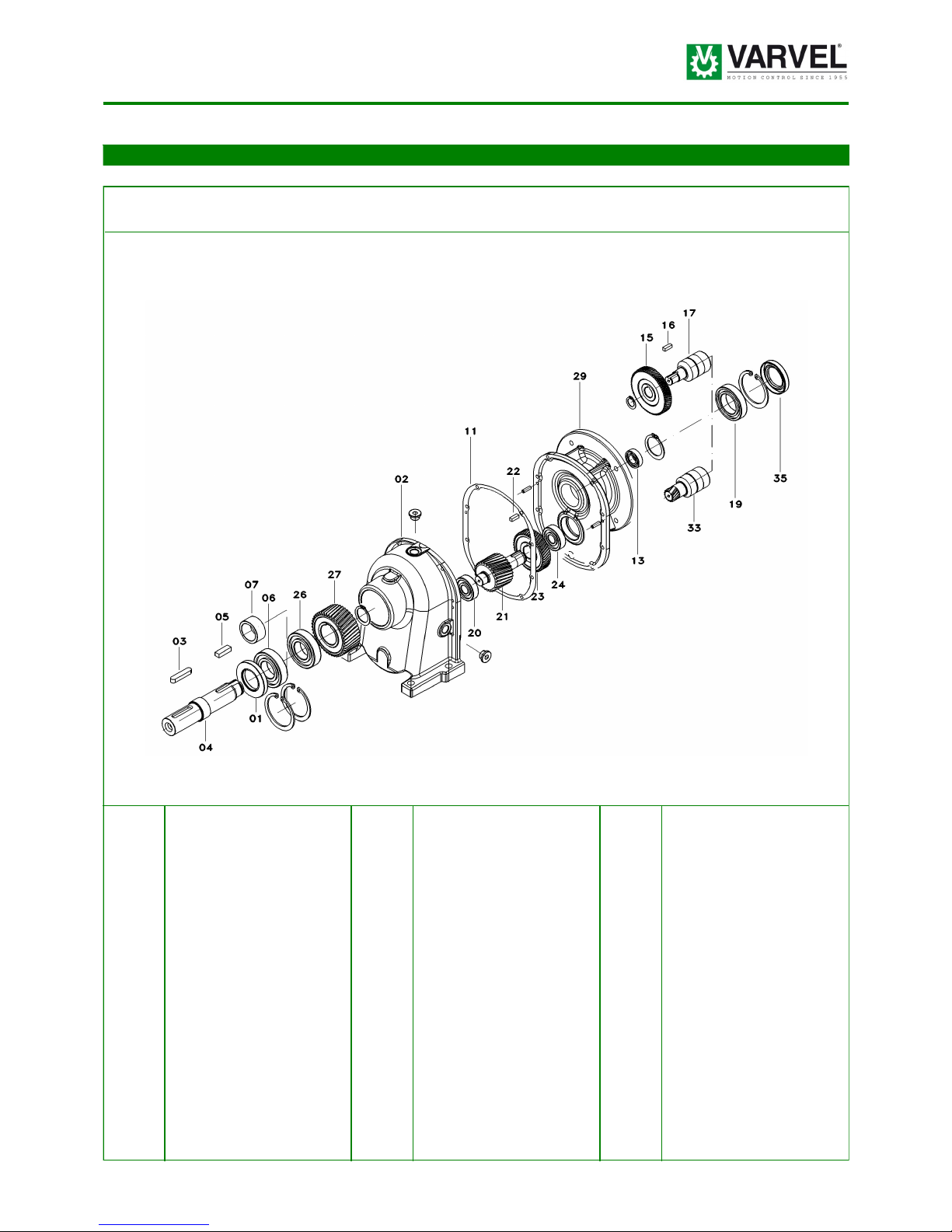
Series RC - 2 stages
The layout shows the general structure of a two-stage foot-mounted helical gearbox type FRC (sizes 05 to 30).
RC
01 Oil seal 19 Bearing
02 Housing 20 Bearing
03 Key 21 Pinion
04 Output shaft 22 Key
05 Key 23 Gear
06 Bearing 24 Bearing
07 Spacer 26 Bearing
11 Gasket 27 Gear
13 Bearing 29 IEC input cover
15 Pinion 33 Hollow input
16 Key 35 Oil seal
17 Hollow input
- 6 -
Working Instructions & Maintenance
Product Layout
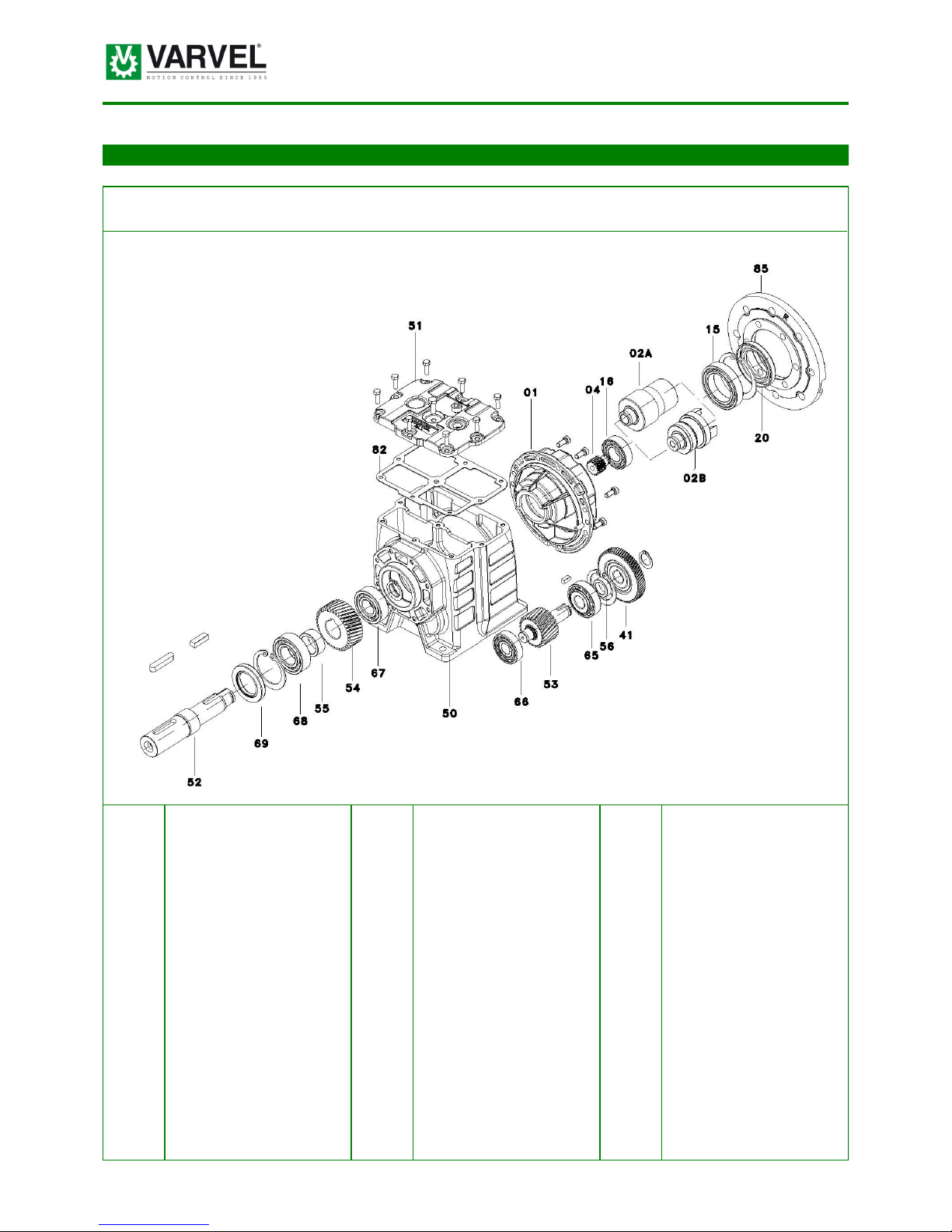
Series RD - 2 stages
The layout shows the general structure of a two-stage foot-mounted helical gearbox type FRD.
RD
01 Input cover 54 Gear
02A Hollow input IEC 55 Spacer
02B Hollow input “G” 65 Bearing
04 Pinion 66 Bearing
15 Bearing 67 Bearing
16 Bearing 68 Bearing
20 Oil seal 69 Oil seal
41 Gear 82 Gasket
50 Housing 85 Motor Flange
51 Upper cover
52 Output shaft
53 Pinion

- 7 -
Working Instructions & Maintenance
Product Layout
Series RD - 3 stages
The layout shows the general structure of a three-stage foot-mounted helical gearbox type FRD.
RD
01 Input cover 40 Pinion 68 Bearing
02A Hollow input IEC 41 Gear 69 Oil seal
02B Hollow input “G” 50 Housing 82 Gasket
03 3rd stage shaft 51 Upper cover 85 Motor flange
04 Pinion 52 Output shaft
05 Gear 53 Pinion
15 Bearing 54 Gear
16 Bearing 55 Spacer
17 Bearing 56 Spacer
18 Bearing 65 Bearing
19 Spacer 66 Bearing
20 Oil seal 67 Bearing
- 8 -
Working Instructions & Maintenance
RG
Product Layout
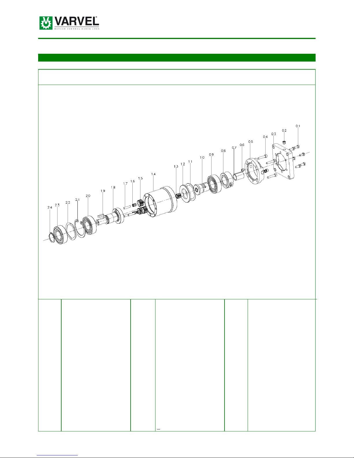
Series RG - 1 stage
The layout shows the general structure of a one-stage reduced backlash planetary gearbox type FRG.
01 Screw 13 Sun gear
02 Plug 14 Ring gear body
03 Motor flange 15 Planet gear
04 Screw 16 Needle bearing
05 Input flange 17 Planet shaft
06 Plug 18 Planet carrier
07 Adapter 19 Key
08 Clamp coupling 20 Bearing
09 Bearing 21 Snap ring
10 Input shaft 22 Shim
11 Shim 23 Bearing
12 Spacer 24 Snap ring
- 9 -
Working Instructions & Maintenance
RG
Product Layout
Series RG - 2 stages
The layout shows the general structure of a two-stage reduced backlash planetary gearbox type FRG.
01 Screw 13 Sun gear 25 Bearing
02 Plug 14 Ring gear body 26 Snap ring
03 Motor flange 15 Planet gear 27 Shim
04 Screw 16 Needle bearing 28 Bearing
05 Input flange 17 Planet shaft 29 Snap ring
06 Plug 18 Planet carrier
07 Adapter 19 Planet gear
08 Clamp coupling 20 Needle bearing
09 Bearing 21 Planet shaft
10 Input shaft 22 Spacer
11 Shim 23 Planet carrier
12 Spacer 24 Key
- 10 -
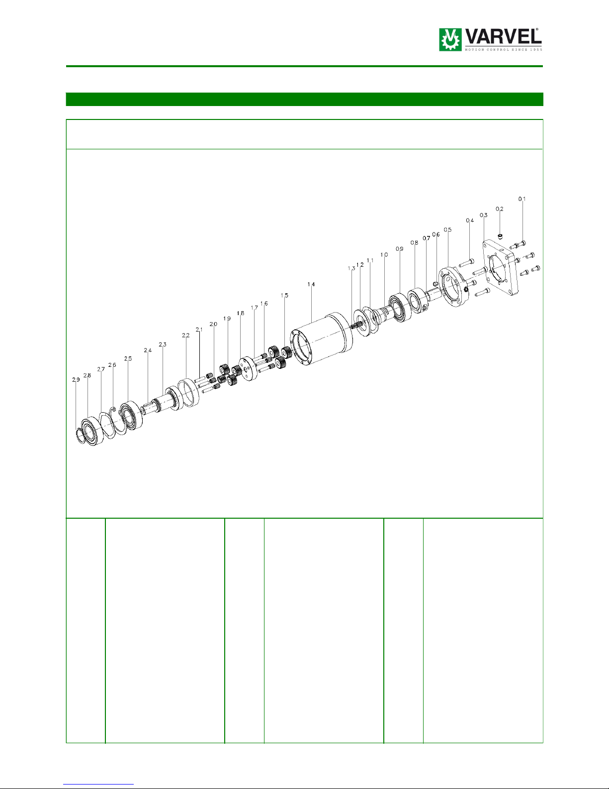
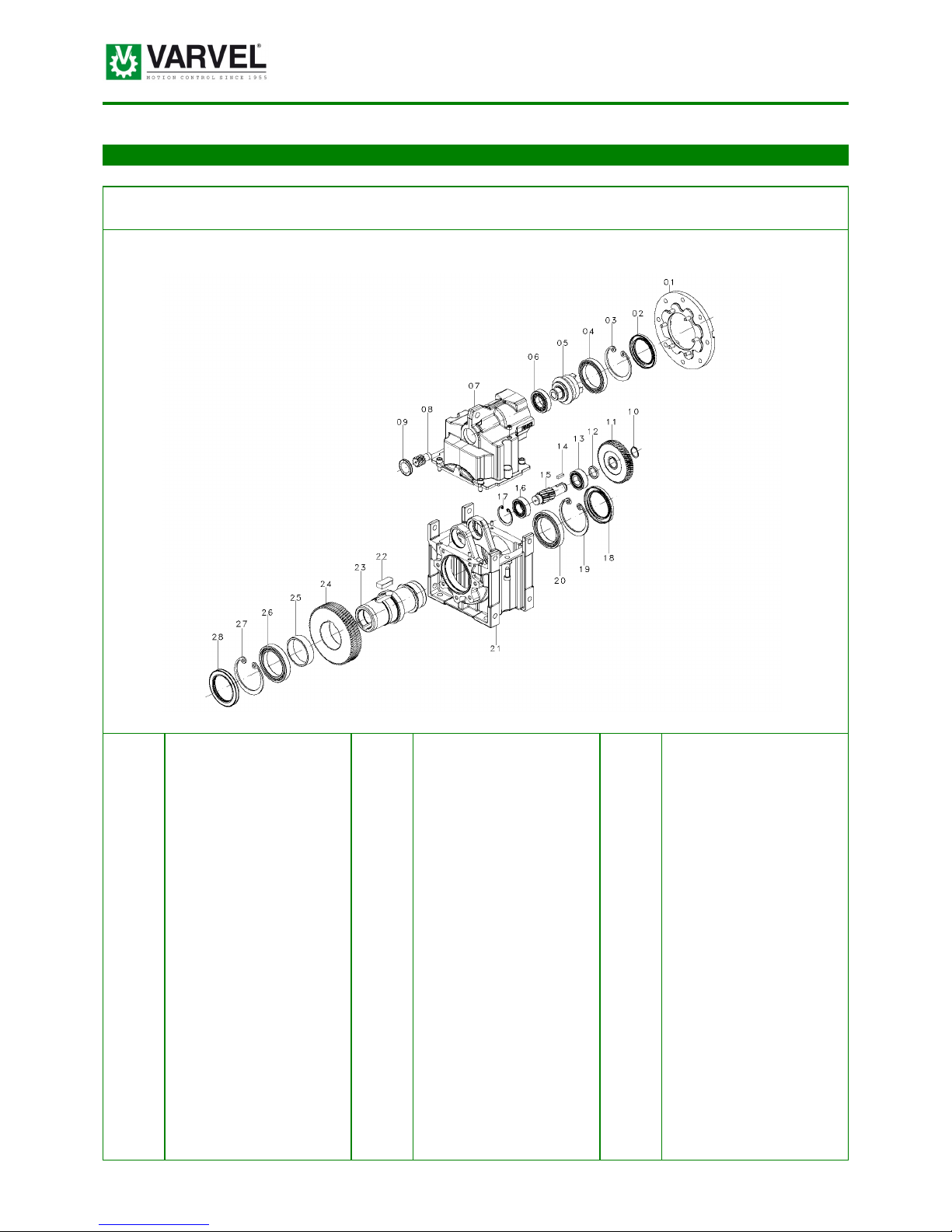
Working Instructions & Maintenance RN
Product Layout
Series RN - 2 stages
The layout shows the general structure of a two-stage parallel shaft gearbox type FRN with through hollow output shaft.
01 Input flange 13 Bearing 25 Spacer
02 Oil seal 14 Key 26 Bearing
03 Snap ring 15 Pinion 27 Snap ring
04 Bearing 16 Bearing 28 Oil seal
05 Input shaft 17 Snap ring
06 Bearing 18 Oil seal
07 Cover 19 Snap ring
08 Pinion 20 Bearing
09 Oil seal RCA 21 Body
10 Snap ring 22 Key
11 Gear 23 Output shaft
12 Spacer 24 Gear
This manual suits for next models
10
Table of contents
Other Varvel Engine manuals


