Black Line BLK-PTZ36XIR User manual

BLK-PTZ36XIR High Resolution IR
36x Zoom Outdoor PTZ Camera
User Manual
Products: BLK-PTZ36XIR
Please read this manual before using your camera, and always follow the instructions for
safety and proper use. Save this manual for future reference.
BLK-PTZ36XIR_CM
1/21/15

ii
REGULATORY NOTICE
FCC Information
FCC compliance: This equipment has been tested and found to comply with the limits for a digital device,
pursuant to part 15 of the FCC Rules. These limits are designed to provide reasonable protection against harmful
interference when the equipment is operated in a commercial environment. This equipment generates, uses, and
can radiate radio frequency energy and, if not installed and used in accordance with the instruction manual, may
cause harmful interference to radio communications. Operation of this equipment in a residential area is likely to
cause harmful interference in which case the user will be required to correct the interference at his own expense.
FCC Conditions
This device complies with part 15 of the FCC Rules. Operation is subject to the following two conditions:
1. This device may not cause harmful interference.
2. This device must accept any interference received, including interference that may cause undesired operation.
This product and - if applicable - the supplied accessories too are marked with “CE” and
comply therefore with the applicable harmonized European standards listed under the Low
Voltage Directive 2006/95/EC, the EMC Directive 2004/108/EC.
LEGAL NOTICE
Observint Technologies (Observint) products are designed to meet safety and performance standards with the use of
specic Observint authorized accessories. Observint disclaims liability associated with the use of non-Observint
authorized accessories.
The recording, transmission, or broadcast of any person’s voice without their consent or a court order is strictly
prohibited by law.
Observint makes no representations concerning the legality of certain product applications such as the making,
transmission, or recording of video and/or audio signals of others without their knowledge and/or consent. We
encourage you to check and comply with all applicable local, state, and federal laws and regulations before
engaging in any form of surveillance or any transmission of radio frequencies.
The BLACK Line is a trademark of Observint Technologies.
Other trademarks and trade names may be used in this document to refer to either the entities claiming the marks
and names or their products. Observint disclaims any proprietary interest in trademarks and trade names other than
its own.
No part of this document may be reproduced or distributed in any form or by any means without the express written
permission of Observint
© 2013, 2015 by Observint Technologies.All Rights Reserved.
11000 N. Mopac Expressway, Building 300, Austin, TX 78759
For Sales and Support, please contact your distributor.
iii
36x PTZ IR Outdoor Camera User Manual
SAFETY WARNINGS AND CAUTIONS
Safety Warnings and Cautions
WARNING
!Hazardous Voltage may be present: Special measures and precautions must be taken when using this device.
Some potentials (voltages) on the device may present a hazard to the user. This device should only be used by those with
knowledge and training in working with these types of devices that contain live circuits.
WARNING
!Power Supply Hazardous Voltage: AC voltages are present within the power supply assembly. This device must be
connected to a UL approved, completely enclosed power supply, of the proper rated voltage and current. No user serviceable
parts inside the power supply.
WARNING
!Connect only to a properly earth grounded outlet. To avoid shock, ensure that all AC wiring is not exposed and that
the earth grounding is maintained. Ensure that any equipment to which this device will be attached is also connected to
properly wired grounded receptacles and are approved medical devices.
WARNING
!
Power Connect and Disconnect: The AC power supply cord is the main disconnect device to AC power. The socket outlet
must be installed near the equipment and must be readily accessible.
Installation and Maintenance: Do not connect/disconnect any cables to or perform installation/maintenance on this
device during an electrical storm.
WARNING
!
Power Cord Requirements: The connector that plugs into the wall outlet must be a grounding-type male plug designed
for use in your region. It must have certication marks showing certication by an agency in your region. The connector that
plugs into the AC receptacle on the power supply must be an IEC 320, sheet C13, female connector. See the following website
for more information http://kropla.com/electric2.htm.
WARNING
!
Lithium Battery: This device contains a Lithium Battery. There is a risk of explosion if the battery is replaced by an
incorrect type. Dispose of used batteries according to the vendor’s instructions and in accordance with local environmental
regulations.
Perchlorate Material: Special handling may apply. See www.dtsc.ca.gov/hazardouswaste/perchlorate. This notice is
required by California Code of Regulations, Title 22, Division 4.5, Chapter 33: Best Management Practices for Perchlorate
Materials. This device includes a battery which contains perchlorate material.

iv
SAFETY WARNINGS AND CAUTIONS
CAUTION
Management Practices for Perchlorate Materials. This device includes a battery which contains perchlorate material.
Electromagnetic Interference: This equipment has not been tested for compliance with emissions limits of FCC and
similar international regulations. This device is not, and may not be, oered for sale or lease, or sold, or leased until
authorization from the United States FCC or its equivalent in other countries has been obtained. Use of this equipment in a
residential location is prohibited. This equipment generates, uses and can radiate radio frequency energy which may result
in harmful interference to radio communications. If this equipment does cause harmful interference to radio or television
reception, which can be determined by turning the equipment on and o, the user is required to take measures to eliminate
the interference or discontinue the use of this equipment.
Warnings
• Use of the product only when in compliance with local electrical safety regulations.
• Use only the required power adapter. The standard power adapter is 24 Vac / 2 A.
• Do not connect additional devices to the power adapter. Doing so may over-heat the device and cause a re hazard.
• Always make sure that the power adapter plug is fully inserted into the power socket.
• When the product is installed on a wall or ceiling, it must be securely attached.
• If the camera emits smoke, odors or noise power it o immediately and unplug the power cable. Contact the service center.
• If the camera does not work properly, please contact your dealer or the nearest service center. Never attempt to disassemble
the camera yourself. (Your provider is not responsibility for problems caused by unauthorized repair or maintenance.)
Cautions
• Do not drop the dome or subject it to physical shock. Do not expose it to high levels of electromagnetic radiation.
• Do not install the camera on surfaces that are subject to vibrations or shock.
• Do not place the camera in extremely hot, cold (operating temperature range: -22 °F ~ 149 °F (-30 °C ~ +65°C)),
dusty or damp locations. Fire or electrical shock can occur.
• Exposing the equipment to direct sunlight, low ventilation or heat sources such as heater or radiator should be avoided.
• Do not aim the camera at the sun or extra bright places. A blooming or smear may occur (which is not a malfunction however),
and aect the longevity of CCD.
• Use the glove provided when opening the dome cover. Do not touch the dome cover; the acidic moisture on skin can erode the
surface coating.
• Please use a soft and dry cloth when cleaning the inside and outside surfaces of the dome cover. Do not use alkaline
detergents.

v
36x PTZ IR Outdoor Camera User Manual
PREPARATION FOR INSTALLATION
Preparation for Installation
• Basic requirements:
—All the electronic operations must be compliant with local electrical safety regulations, re prevention regulations and
other related regulations.
—Verify that all accessories are included with your shipment.
—Make sure that the camera is suitable for the location and security requirements where it will be installed. If not, please
contact the supplier.
—Always use this product in accordance with the manufactures specications and recommendations.
• Check installation space. Make sure the place have enough space to install the camera and its accessories.
• Check the intensity of conformation at the installation location. Please make sure that the ceilings or walls are strong enough to
withstand four times the weight of camera and its accessories.
• Preparation of cables:
—Choose video cable in accordance with the transmission distance. The video should meet the least demands as: 75 Ω
resistance; 100% copper core conducting wire; 95% weaving copper shield.
—For RS-485 communication cable, please refer to Appendix B.
—For 24 Vac power cabling, please refer to Appendix C.
• Keep packaging for possible future use. If a failure occurs, return the product to the factory with the original packaging.
Shipment without the original packaging may damage the product and incur additional costs.

vi
TABLE OF CONTENTS
Table of Contents
SECTION 1 Introduction .......................................................................1
1.1 Features ............................................................................1
1.2 Accessories..........................................................................4
SECTION 2 Installation ........................................................................8
2.1 Setup the camera address and baud rate DIP switches .....................................8
2.2 Camera wall mount installation .......................................................10
2.3 Connecting the cables ...............................................................12
SECTION 3 Getting Started ....................................................................14
3.1 Power-up initial display..............................................................14
3.1.1 Basic operations................................................................15
3.2 System-dened Presets .............................................................15
3.2.1 Manchester code control protocols ................................................16
3.3 On Screen Displays ..................................................................16
SECTION 4 Using the OSD Menus ...............................................................17
4.1 Accessing and operating the menus. . . . . . . . . . . . . . . . . . . . . . . . . . . . . . . . . . . . . . . . . . . . . . . . . . . .17
4.2 Conguring System Information ......................................................19
4.2.1 Checking System Information ....................................................19
4.2.2 Conguring system parameters...................................................19
4.2.3 System time conguration .......................................................22
4.2.4 Display the PTZ movements, system time, fan/heat, etc...............................22
4.2.5 IR parameter conguration ......................................................23
4.3 Conguring Image Parameters........................................................25
4.3.1 TASK 1. Congure the focus settings ...............................................25
4.3.2 TASK 2. Congure the zoom settings...............................................26
4.3.3 TASK 3: Congure the Day/Night mode ............................................26
4.3.4 TASK 4: Congure the sharpness level..............................................27
4.3.5 Task 5: Congure the BLC and WDR ...............................................27
4.3.6 TASK 6. Congure iris, gain and shutter speed.......................................27
4.3.7 TASK 8: Congure white balance ..................................................28
4.3.8 TASK 9: Congure the image ip ..................................................29
4.3.9 TASK 10: Congure the INIT LENS. . . . . . . . . . . . . . . . . . . . . . . . . . . . . . . . . . . . . . . . . . . . . . . . . .29
4.3.10 TASK 11: Congure noise reduction................................................29
4.3.11 TASK 12: Congure the image quality..............................................29

vii
36x PTZ IR Outdoor Camera User Manual
TABLE OF CONTENTS
4.3.12 Conguring Privacy Mask ........................................................29
4.4 Conguring PTZ control parameters....................................................31
4.4.1 Conguring PTZ parameters......................................................31
4.5 Conguring Presets .................................................................33
4.5.1 TASK 1: Set a preset .............................................................33
4.5.2 TASK 3: Call the presets..........................................................34
4.5.3 TASK 2: Clear the preset settings ..................................................34
4.6 Conguring Patrols..................................................................34
4.6.1 TASK 1: Set a patrol .............................................................34
4.6.2 TASK 2: Preview the patrol .......................................................36
4.6.3 TASK 3: Delete a patrol ..........................................................36
4.6.4 TASK 4: Call the dened patrol ...................................................36
4.6.5 Set the dwell time when running a fast patrol ......................................37
4.7 Conguring Patterns ................................................................37
4.7.1 TASK 1: Set a pattern ............................................................37
4.7.2 TASK 2: Preview a pattern........................................................38
4.7.3 TASK 3: Call the dened pattern. . . . . . . . . . . . . . . . . . . . . . . . . . . . . . . . . . . . . . . . . . . . . . . . . . .38
4.7.4 TASK 4: Delete patterns..........................................................38
4.8 Conguring Time Tasks...............................................................39
4.8.1 TASK 1: Set time tasks ...........................................................39
4.8.2 TASK 2: Delete the task. .........................................................40
4.9 Conguring Zones...................................................................40
4.9.1 TASK 1: Set a zone...............................................................41
4.9.2 Clearing PTZ Control Settings.....................................................42
4.9.3 Using the DIAGNOSTICS display ...................................................42
4.10 Others.............................................................................43
4.10.1 Conguring dome authentication .................................................43
4.10.2 Restoring default dome settings ..................................................44
4.10.3 Restoring camera default settings.................................................45
4.10.4 Rebooting the camera...........................................................45
SECTION 5 Specications .....................................................................46
APPENDIX A Lightning and Surge Protection ......................................................48
APPENDIX B RS-485 Bus Connection .............................................................49
APPENDIX C 24 Vac Wire Gauge and Transmission Distance ..........................................52

viii

1
36x PTZ IR Outdoor Camera User Manual
SECTION 1: INTRODUCTION
SECTION 1
Introduction
The BLACK Line™ 700 TVL 36x zoom outdoor PTZ camera enables you to pan, tilt and zoom in on activity both near and far, and
features high-powered 320’ IR LEDs to capture high-resolution video day and night. The PTZ camera has an extreme operating
temperature range of -22° F ~ 149° F that is ideal for capturing video in cold climates and an IP66 weather rated enclosure
to withstand a variety of elements and weather conditions. The camera also features privacy zone masking and back light
compensation (BLC) 256x sense up.
1.1 Features
Special features of the camera include:
• Delivers 700 TV lines of resolution (color) 750 TV lines (B/W)
• 1/4” Sony 960H CCD image sensor
• 36x optical zoom, 16x digital zoom
• Long range 320’ IR
• Enhanced imaging with D-WDR and 3D-DNR
• True day/night (ICR) to capture sharp, detailed images day and night
• 360° endless pan range, -55° ~ -90° tilt range, 0.1°/s ~ 240°/s pan speed and 0.1°/s ~ 120°/s tilt speed
• Extreme operating temperature: -22 °F ~ 149 °F
• IP66 weather rated
• TVS 4,000V lightning/surge protection
OSD (on-screen display)
The on-screen display is a text image superimposed on video. The text displays status information and conguration menus.
Self-adaptive Protocol
The camera is compatible with PELCO-D, PELCO-P, PRIVATE-Code, VICON and KALATEL-312 protocols, etc., and is capable of being
self-adaptive to these protocols without selecting protocol by DIP switch settings.
Keyboard Control
The pan/tilt movement and zoom actions of camera can be controlled by the control keyboard, DVR, matrix, etc.
Limit Stops
The dome can be programmed to move within the limit stops (left/right, up/down) which are congurable by the control keyboard,
DVR or client application software.

2
SECTION 1: INTRODUCTION
Scan Modes
The dome provides 5 scanning modes: pan scanning, tilt scanning, frame scanning, random scanning and panorama scanning.
Preset Freezing
This feature freezes the scene on the monitor when moving to a preset. This allows for smooth transition from one preset scene to
another and also guarantees that masked areas will not be revealed when moving to a preset.
Presets
Each of the user-denable presets can be programmed to use pan, tilt, camera settings and other settings. When a preset is called,
the dome will automatically move to the dened position. The user can add, modify, delete and call each preset.
Label Display
The on-screen label of the preset title, PT display, zoom, and time can be displayed on the monitor.
Auto Flip
In manual tracking mode, when a target object moves directly beneath the dome, the dome will automatically rotate 180 degrees
in the horizontal direction to maintain continuity of tracking.
Privacy Mask
The privacy mask allows the user to dene areas of the eld of view that cannot be seen by the operator of the camera. A masked
area will move with pan and tilt functions and automatically adjust in size when the lens zoom changes.
3D Positioning
The camera can be controlled with a mouse and the PRIVATE-Code protocol. Clicking a spot can direct the camera position the spot
in the center of the image. When a rectangular area is selected with the left mouse button, the camera will move to its center and
enlarge it. Right click the mouse to zoom in. The scroll wheel can control lens zoom. Mouse cursor movement can also control zoom
eects.
Proportional Pan/Tilt
Proportional pan/tilt automatically reduces or increases the pan and tilt speeds in proportion to the amount of zoom. At telephoto
zoom settings, the pan and tilt speeds are slower than at wide zoom settings. This keeps the image from moving too fast on the
monitor when there is a large amount of zoom.
Auto Focus
Auto focus enables the camera to focus automatically to maintain clear video images.
Day/Night Auto-switch
The camera provides color images during the day. As light diminishes at night, it switches to night mode and delivers black and
white images with high quality.

3
36x PTZ IR Outdoor Camera User Manual
Slow Shutter
Slow shutter function extends the exposure time to accumulate more light when the light condition is low, resulting in a brighter
image.
Backlight Compensation (BLC)
Back Light Compensation ensures proper exposure of subjects in the foreground. Back light compensation adjusts the camera’s
exposure in challenging lighting environments such as hallways and doorways, so the entire image of the subject in the foreground
is properly exposed when there is a bright light source behind the subject.
Wide Dynamic Range (WDR)
This feature enables the camera to produce clearer images in less than ideal lighting conditions. WDR balances the contrast of light
and shadow to improve visibility in dark areas within a scene.
White Balance
White balance is the white rendition function of the camera to automatically adjust the color temperature according to the
environment. It can remove the unrealistic color casts in the image.
Patrol
The camera provides up to 8 patrols. In each patrol, you can specify the scanning track by a group of user-dened presets, with the
scanning speed between two presets and the dwell time at the preset separately programmable.
Pattern
A pattern is a memorized, repeating series of pan, tilt, zoom, and preset functions that can be recalled with a command from
a controller or automatically by a congured function. By default the focus and iris are in auto status during the preset is being
memorized.
Power-o Memory
This feature causes the camera to resume its previous position or status after power is restored.
Time Task
A time task is a precongured action that can be performed automatically at a specic date and time. The programmable actions
include: preset 1-8, pattern 1-4, patrol 1-4, pan scan, tilt scan, random scan, frame scan, panorama scan, day/night mode or none.
Park Action
This feature allows the dome to start a predened action automatically after a period of inactivity.
SECTION 1: INTRODUCTION

4
1.2 Accessories
The following accessories are available for the BLK-PTZ36XIR camera. Mounting bracket detail is shown below.
Model Type
BLK-PTZCL Ceiling Mount Bracket
BLK-PTZWB Wall Mount Bracket
BLK-PTZPM Pole Mount PTZ Bracket
BLK-PTZCM Corner Mount PTZ Bracket
BLK-PTZCNTRL 3D Joystick PTZ Controller (Pelco-P/D)
BLK-PTZCL: Ceiling Mount Bracket
The Ceiling Mount Bracket is suitable for outdoor ceiling mounting.
3.52"dia.
0.39"dia. (4)
2.24"
4.57"dia.
SECTION 1: INTRODUCTION
5
36x PTZ IR Outdoor Camera User Manual
SECTION 1: INTRODUCTION
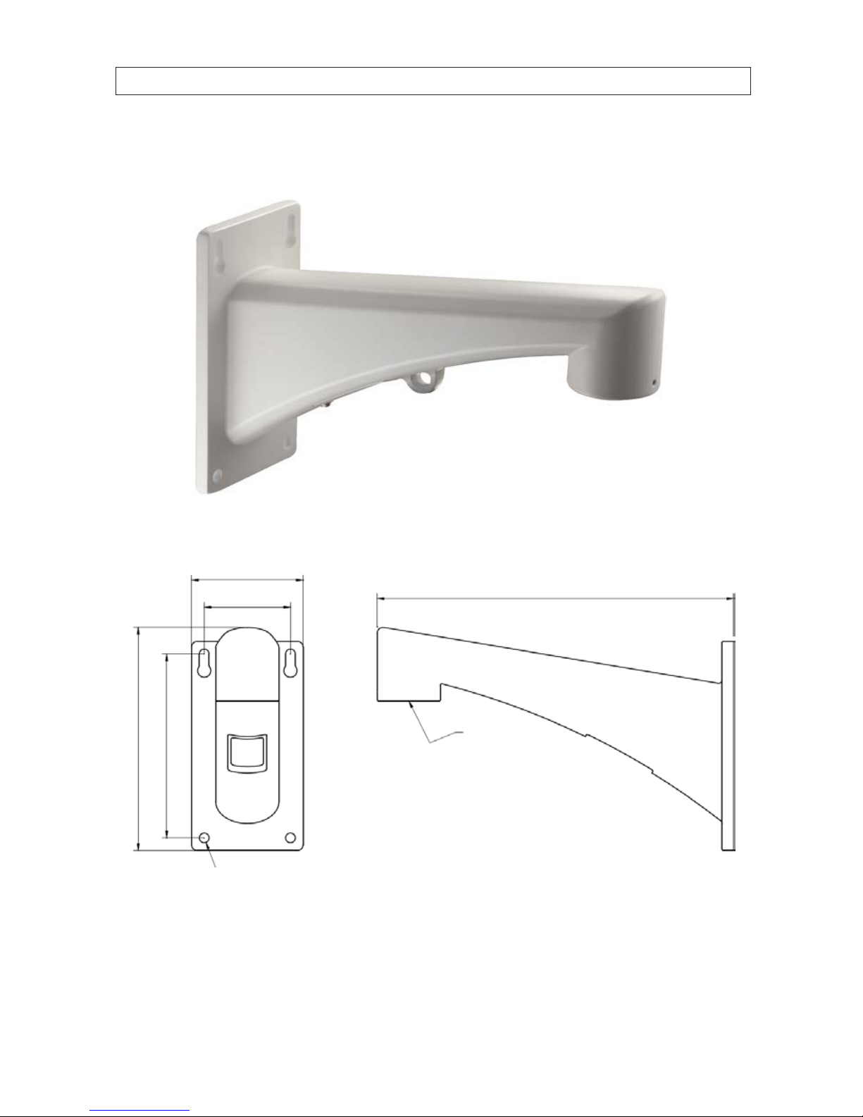
BLK-PTZWB: Wall Mount Bracket
The Wall Mount Bracket is suitable for indoor and outdoor wall mounting.
0.33"dia. (4)
G 1.5"
6.30"
7.6 4"
2.95"
3.82"
12.2"
6
SECTION 1: INTRODUCTION
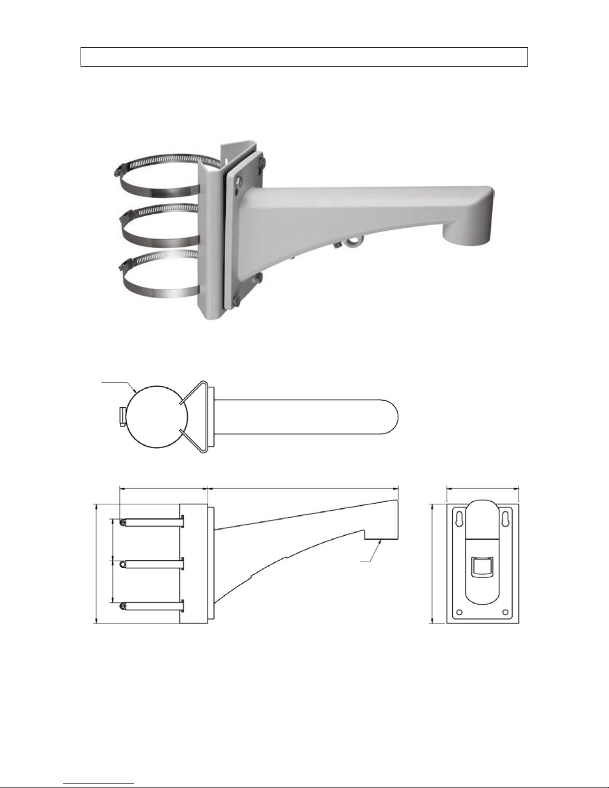
BLK-PTZPM: Pole Mount PTZ Bracket
The Pole Mount Bracket is suitable for outdoor pole mounting. The straps can attach to a 2.64" ~ 5.00" diameter pole.
2.68"2.68"
7.6 4"
7.6 4"
5.63"
3.94"dia.
G 1.5"
12.2"4.61"

7
36x PTZ IR Outdoor Camera User Manual
SECTION 1: INTRODUCTION
BLK-PTZCM: Corner Mount PTZ Bracket
7.6 4"
6.96"
G 1.5"
16.52"

8
SECTION 2: INSTALLATION
SECTION 2
Installation
Before you start, check the package contents and make sure that the device in the package is in good condition and all the assembly
parts are included. Included are:
• AC power supply
• Installation guide (this user manual)
Mounting brackets are sold separately.
2.1 Setup the camera address and baud rate DIP switches
DIP switches inside the camera are used to manually congure the RS-485 device address and network baud rate. The device
address and baud rate can also be congured remotely through the OSD (on-screen display) using a control console, DVR or DVS.
See “SECTION 4 Using the OSD Menus” on page 17 for more information.
NOTE If you are installing several RS-485 network devices at the same time, manually setting the DIP switches for address and
baud rate will help reduce connectivity issues during the initial setup of those devices.
There are two DIP switch groups, SW1 switches 1 .. 8 (sets the RS-485 network address) and SW2 switches 1 and 2 (sets the
RS-485 network baud rate). The address setup for the camera must be unique for each device on the RS-485 network. However,
the baud rate switched must be congured to the same baud rate used by the other devices on the network. These switches are
accessible when the “SWITCH” cover is removed. To setup the DIP switches, do the following:
1. While viewing the camera from the underside, remove the plate marked “SWITCH”.
DIP switch
setting examples
SWITCH
cover plate

9
36x PTZ IR Outdoor Camera User Manual
SECTION 2: INSTALLATION
2. Locate DIP switch packages SW1 (switches 1 .. 8) and SW2 (switches 1, 2).
3. Set the device address DIP switches 1 through 8 using the following table. Each device on the RS-485 network must have
a dierent address. You can congure up to 256 devices (address 0 .. 255) on the RS-485 network. The switch package
indicates which position is ON and which is OFF.
Table 1. DIP address switch settings
Dome Address
SW1 (address) switch number
12345678
0OFF OFF OFF OFF OFF OFF OFF OFF
1ON OFF OFF OFF OFF OFF OFF OFF
2OFF ON OFF OFF OFF OFF OFF OFF
3ON ON OFF OFF OFF OFF OFF OFF
4OFF OFF ON OFF OFF OFF OFF OFF
5ON OFF ON OFF OFF OFF OFF OFF
6OFF ON ON OFF OFF OFF OFF OFF
7ON ON ON OFF OFF OFF OFF OFF
8OFF OFF OFF ON OFF OFF OFF OFF
9ON OFF OFF ON OFF OFF OFF OFF
… ……………………
255 ON ON ON ON ON ON ON ON
4. Set the network baud rate DIP switches 1 and 2 using the following table. Each device on the RS-485 network must use the
same baud rate. By default, the baud rate is set to 2400 baud (1 gOFF, 2 gOFF).
Baud rate
SW2 switches
1 2
2400 OFF OFF
2400 ON OFF
4800 OFF ON
9600 ON ON
5. Reinstall the SWITCH cover plate.

10
2.2 Camera wall mount installation
The camera can be wall mounted to any indoor or outdoor solid wall. The instructions below detail a wall mounting installation of
the camera. For ceiling and corner mounting installations, use the following as a guideline.
NOTE • The wall must be thick enough to mount the expansion screws.
• The wall must be strong enough to withstand more than 4 times the weight of the dome and its accessories.
1. Prepare the mounting surface for the camera and mounting bracket.
a. Obtain the best fasteners for attaching the camera wall mount bracket to the mounting surface. The fasteners must t
the wall mount bracket and should support at least eight times the weight of the camera and mounting bracket.
b. Position the wall mount bracket in the location where you want to install it, then use it as a guide to mark the location
of the screw holes.
Loop for
safety rope
Screws (4)
Set screw (2)
Wall mount installation
c. Drill four screw holes according to the screw holes on the wall mount.
d. Drill a 1-1/4" hole in the mounting surface between the mounting screws appropriate for the camera drop and
interface cables.
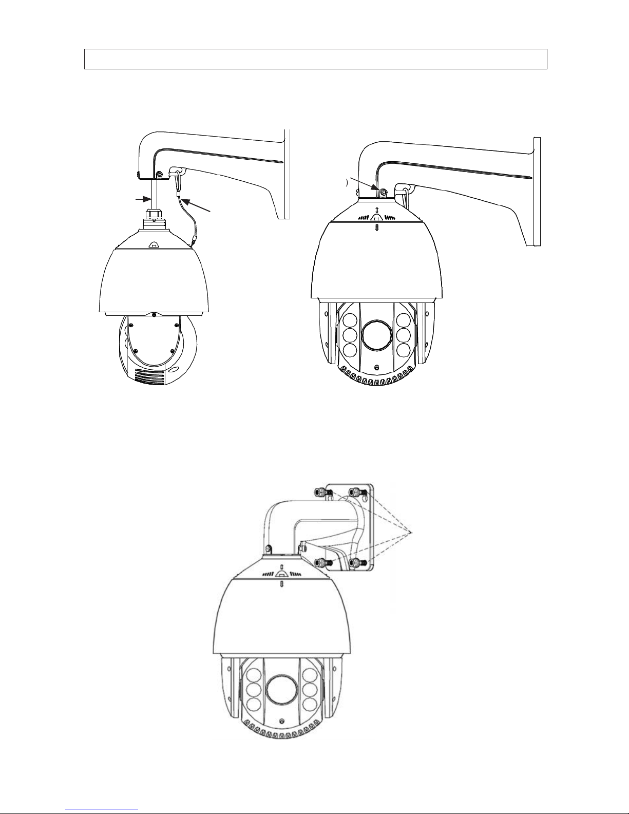
2. Secure the camera onto the wall mount bracket as shown below:
a. Route the camera drop cables through the wall mount bracket.
b. Rotate the connector of the camera housing onto the wall mount bracket.
SECTION 2: INSTALLATION
11
36x PTZ IR Outdoor Camera User Manual
SECTION 2: INSTALLATION
c. Tighten the set screws with the hex wrench (supplied) to hold the two units together.
Safety rope
Lock
screw (2)
Drop cable
Secure the camera to the bracket
3. Route the camera drop cables through the hole for them drilled in the mounting surface.
4. Using four fasteners, secure the camera to the mounting surface.
Screw (4)

12
SECTION 2: INSTALLATION
5. Remove the protective tape from camera.
Protective
tape
Remove protective tape
2.3 Connecting the cables
1. Route network cables for video, 24 Vac power and ground, and RS-485 between the remote control device and power source
and your camera. Do not apply power to the 24 Vac cables before connecting them to your camera.
Remote control device (DVR)Camera Monitor
Network cabling
2. Connect the network power and ground, RS-485, and video cables to the camera drop cable connectors.
Table of contents
Other Black Line Security Camera manuals


