Page 3 — English
IMPORTANT SAFETY INSTRUCTIONS
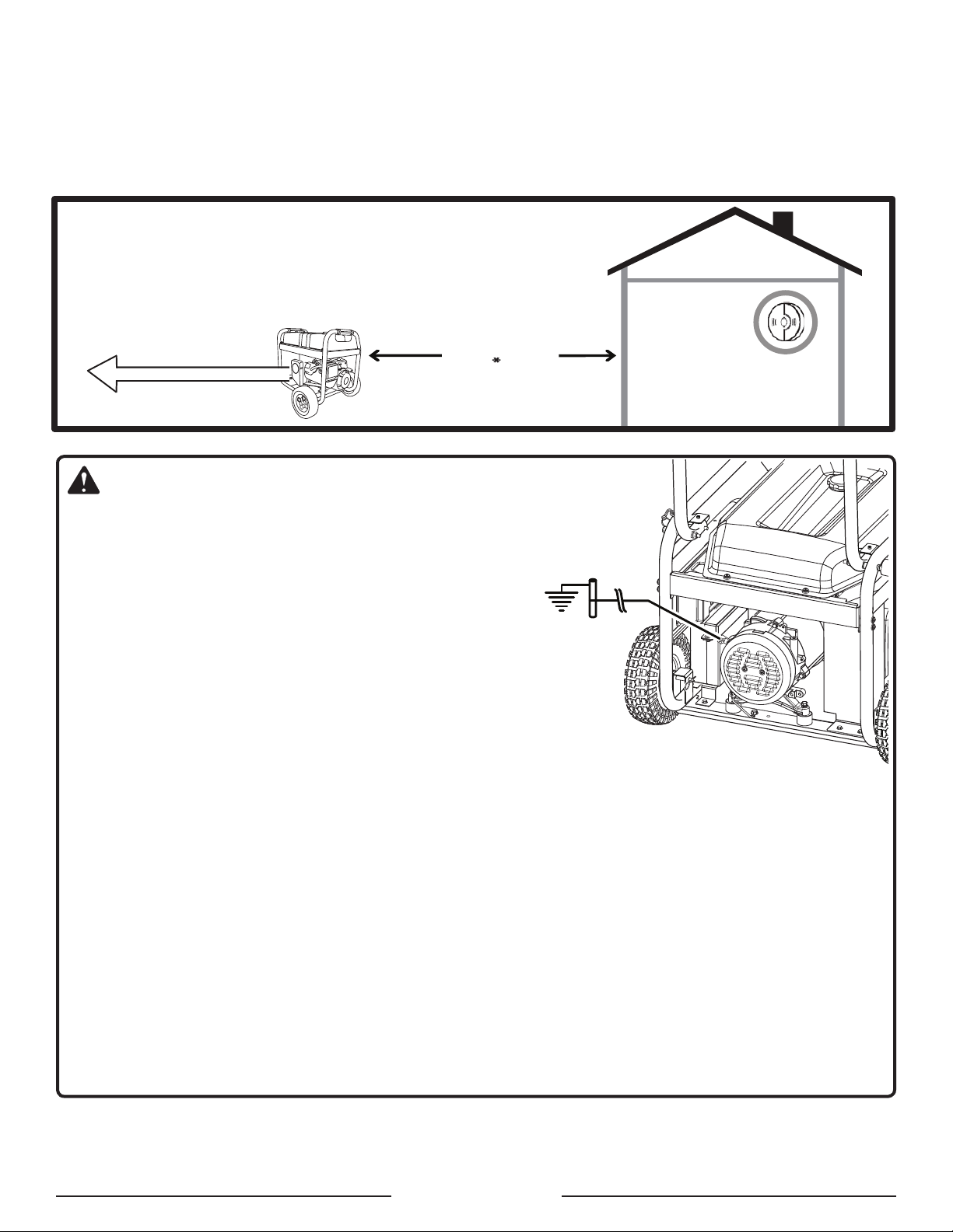
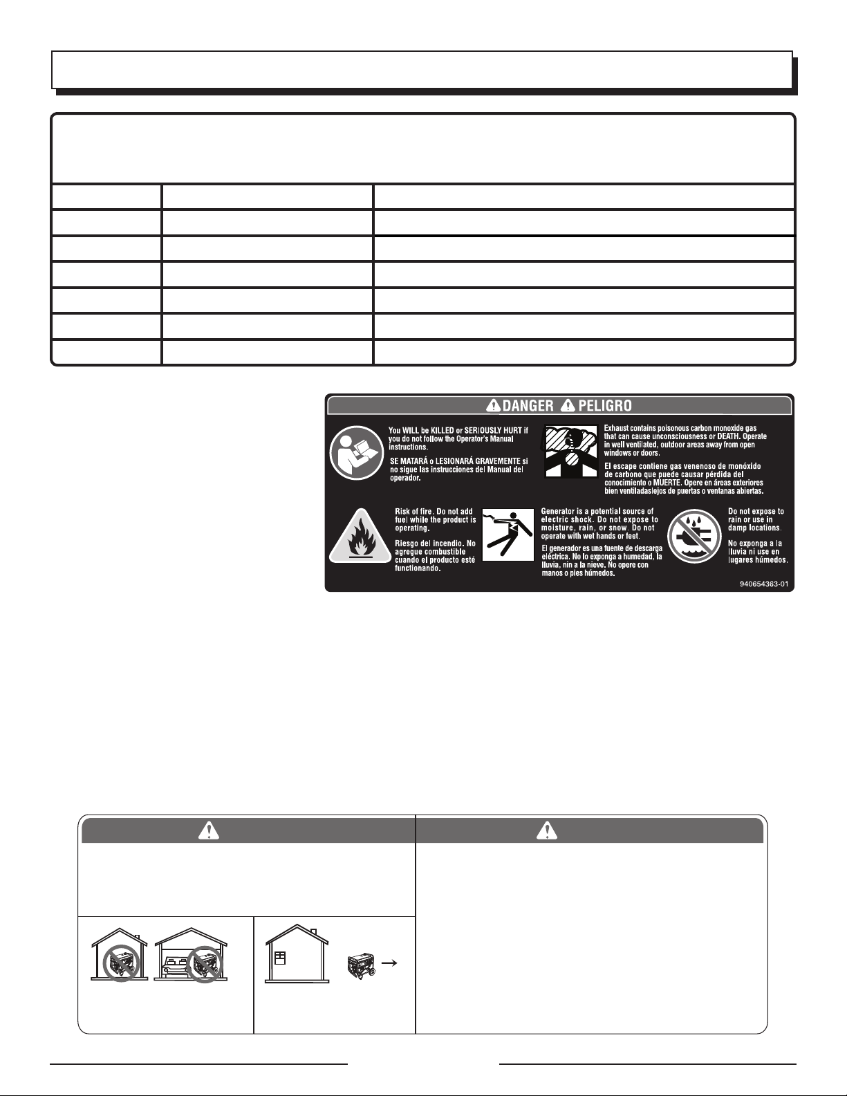
DANGER:
Carbon Monoxide. Using a generator indoors CAN KILL
YOU IN MINUTES.
Generator exhaust contains high levels of carbon
monoxide (CO), a poisonous gas you cannot see or smell.
If you can smell the generator exhaust, you are breathing
CO. But even if you cannot smell the exhaust, you could
be breathing CO.
Never use a generator inside homes, garages,
crawlspaces, or other partly enclosed areas. Deadly
levels of carbon monoxide can build up in these
areas. Using a fan or opening windows and doors
does NOT supply enough fresh air.
ONLY use a generator outdoors and far away from
open windows, doors, and vents. These openings
can pull in generator exhaust.
Even when you use a generator correctly, CO may
leak into the home. ALWAYS use a battery-powered or
battery-backup CO alarm in the home.
If you start to feel sick, dizzy, or weak after the generator
has been running, move to fresh air RIGHT AWAY. See
a doctor. You could have carbon monoxide poisoning.
WARNING:
Read and understand all instructions. Failure to follow
all instructions listed below could result in electrocution,
fire, and/or carbon monoxide poisoning, which can cause
death or serious injury.
WARNING:
In some applications, National Electric Code requires
generator to be grounded to an approved earth ground.
Before using the ground terminal, consult a qualified
electrician, electrical inspector, or local agency having
jurisdiction for local codes or ordinances that apply to
the intended use of the generator.
SAVE THESE INSTRUCTIONS
This manual contains important instructions that should be
followedduring installationand maintenanceofthe generator.
Do not connect to a building’s electrical system unless
the generator and transfer switch have been properly
installed and the electrical output has been verified by
a qualified electrician. The connection must isolate the
generator power from utility power and must comply with
all applicable laws and electrical codes.
Do not allow children or untrained individuals to use this
unit.
Do not start or operate the engine in a confined space,
building,nearopen windows, orinotherunventilated space
where dangerous carbon monoxide fumes can collect.
Carbon monoxide, a colorless, odorless, and extremely
dangerous gas, can cause unconsciousness or death.
Keep all bystanders, children, and pets at least 10 feet
away.
Wear sturdy and dry shoes or boots. Do not operate while
barefoot.
Do not operate generator when you are tired or under the
influence of drugs, alcohol, or medication.
Keep all parts of your body away from any moving parts
and all hot surfaces of the unit.
Do not touch bare wire or receptacles.
Do not use generator with electrical cords which are worn,
frayed, bare, or otherwise damaged.
Before storing, allow the engine to cool for 30 minutes
and drain fuel from the unit.
Do not operate or store the generator in rain, snow, or
wet weather.
Store the generator in a well-ventilated area with the fuel
tank empty. Fuel should not be stored near the generator.
Empty fuel tank, close fuel valve, and restrain the unit
from moving before transporting in a vehicle.
Provide a plastic sheet or absorbent pad below the
generator to catch any drips of fuel or lubricant when
transporting.
To reduce the risk of fire and burn injury, handle fuel with
care. It is highly flammable.
Do not smoke while handling fuel.
Store fuel in a container approved for gasoline.
Position the unit on level ground, stop engine, and allow
to cool for five minutes before refueling.
Loosen fuel cap slowly to release pressure and to keep
fuel from escaping around the cap.
Tighten the fuel cap securely after refueling.
Wipe spilled fuel from the unit.
Never attempt to burn off spilled fuel under any
circumstances.
Generators vibrate in normal use. During and after the
use of the generator, inspect the generator as well as
extension cords and power supply cords connected to
it for damage resulting from vibration. Have damaged
items repaired or replaced as necessary. Do not use plugs
or cords that show signs of damage such as broken or
cracked insulation or damaged blades.
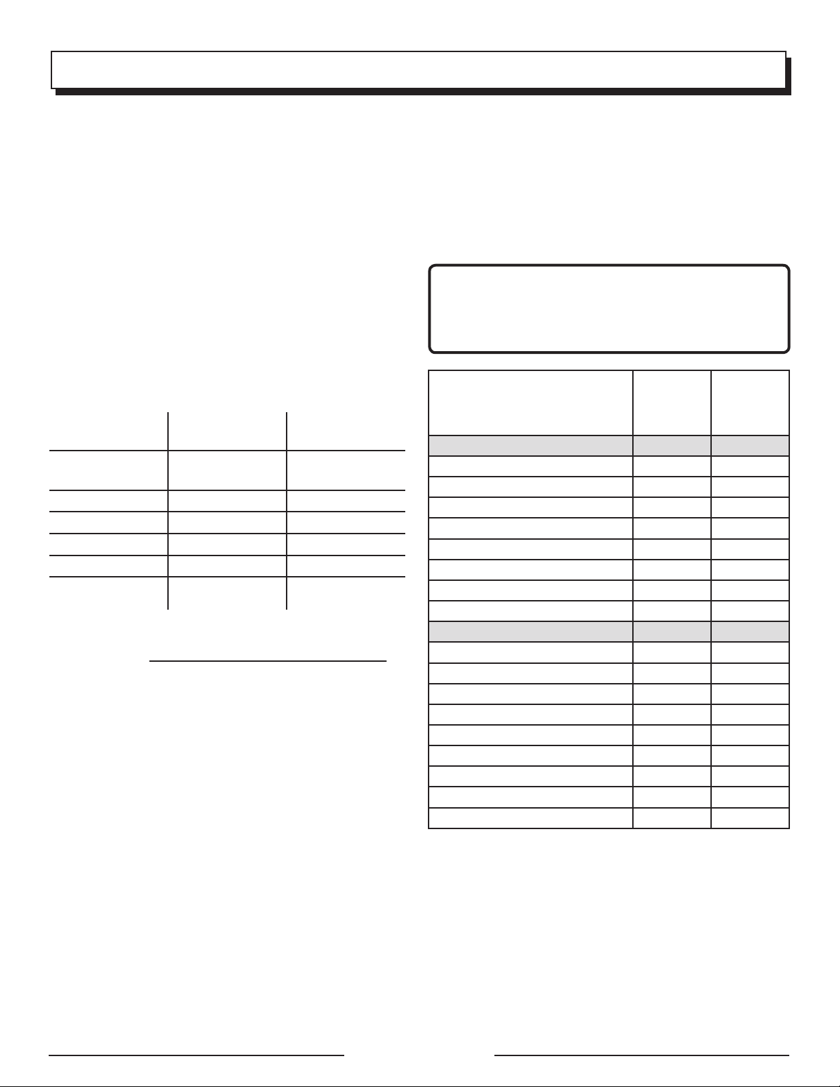
For power outages, permanently installed stationary
generators are better suited for providing back-up power
tothehome. Evenaproperly connected portablegenerator
can become overloaded. This may result in overheating
or stressing the generator components, possibly leading
to generator failure.