Black Max BM905500 User manual
.1.
BLACK
MAX
OPERATOR’S
MANUAL
Manual
del
operador
5,500
WATT
GENERATOR
Generador
de
5
500
W
BM905500
TABLE
OF
CONTENTS
•
Important Safety
Instructions
3-4
•
Specific Safety
Rules
4
•
Symbols
5-7
•
Electrical
8-9
I
Features
10
•
Assembly
11-12
•
Operation
12-15
•
Maintenance
15-18
•
Troubleshooting
19
•
Warranty
20-21
I
Parts
Ordering
I
Service
Back
Page
A
WARNING:
To
reduce
the
risk of
injury,
the user
must
read
and
understand
the operator’s
manual
before
using this
product.
SAVE
THIS
MANUAL
FOR
FUTURE
REFERENCE
iNDICE
DE
CONTEN
100
•
Instrucciones
de
segaddad
importantes
3-4
•
Reglss
dv
seguridsd especificas
4
•
Simbolos
5-7
•
Aspectoa
elictricos
8-9
I
Caracteristicas
10
•
Armado
11-12
•
Funcionamiento
12-15
I
Mantenimiento
15-18
I
Corrección
de
problemas
19
I
Garantia
20-21
•
Pedidos
de
piezas
/servicio
Pig,
posterior
A
ADVERTENCIA:
Para
reducirel
rieago
de
lesiones,
usuaho
debe
teer
y
comprender
el
manual
del
operador
antes
de
ussr
este
producto.
GUARDE ESTE
MANUAL
PARA
FUTURAS CONSULTAS
CUSTOMER SERVICE
1-800-726-5760
To
register
your BtackMax
product,
please
visit:
http://register.bf
ackmaztoof
scorn?
Mexico
SERVICIO
AL
CLIENTE
78008431111
Para
registrar
su
producto
de
BfackMax,
por
favor
visits:
hllp:/Iregister.blackmaxtoots.com/
NOTICE
AVISO
NEUTRAL
BONDED
TO
FRAME
PUNTO NEUTRO CONECTADO
AL
MARCO
Do
not
use
E15
or
E85
fuel
in
this
product.
It
is
a
violation
of
II
federal
law
and
will
damage
the
unit
and
void
your
warranty.
Only
use
unleaded
gasoline
containing
up to
10%
ethanol.
No
utilice
combustibles
E15 oE85
con
este
producto.
Esto
constituye
una
violscion
a
Ia
ley
federal,
danari
Is
unidad
y
anulari
Ia
garantia.
Use
inicamente
gasofina
sin
plomo
con
Un
contenido
de
hasta
10 %
de
etanot.
-,

N-
Fuel
valve
(vdlvula
de
combustible)
o
-
Handle
lock
pin
(pasador
do
seguro
del
mango)
P
-
AC
circud
breakers
(disyuntoro
do
circuito
do
CA)
o
-
Handle
(mango)
R
-
Wheel
(rueda)
S
-
Muff
let
(silenciador)
See
this
fold-out
section
for
all
of
the
figures
referenced
in
the
operator’s
manual.
Consulte
esta
sección desplegable
para
vet
todas
las
figutas
a
las
que
se
hace
referencia
en
el
manual
del
opetador.
2
A(]
A
-
Reset button
(batOn
do
roujuste)
B
-
Test
button
(botdn
do
pruoba)
4
7
1
A
-
Socket
wrench
(have
do
casquillo)
B
-
Adjustable
wrench
(Ilove
ajustablo)
A
-
Handle
release
pin
(conjunto
do
pasador
do
atlojo
do
mango)
B
-
Fuel
cap
(topa
del
tongue
do
combustible)
C
-
Fool
tank (tonque
do
combustible)
D-
120
volt
AC
20
amp
GFCI
receptacles
(120
V
do
CA
20
A
con
GFCI
rocoptdculns)
-240
volt
AC
30
amp
receptacle
(24ff
V
do
ca
30
A
rocoptOculn)
F
-
Oil
cap/dipstick
)tapo
do
rellono
do
acoito
/
varillo
modidnra
do
acoite)
A
-
Lanyard
)cnrroo)
B
-
Handle
lock
pin
(pasador
do
soguro
do
mango)
C
-
Handle
(mango)
0-
Hole
(oguiore)
G
-
Oil
drain
plug
(porno
do
drenaje
do
aceito)
H
-
Stop
switch
(interrupter
del
apagodo)
I
-
Recoil
starter
grip
(mange
dol
orrancodor
rotrOctil)
-
Air
filter
(tiltre
do
airo)
K
-
Choke
(anogadnrj
-
Fuel
tank
vapor
vent
(roepirador
del
vapor
dot
tanque
do
combustible)
M-
Ground
terminal
(tormmal
do
conexiOn
a
tiorra(
A
-
Lock
nut
(tuorcas
do
bloq000)
B
-
Frame (armazOn)
C
-
Rubber
foot
(pie
de
goma)
0-
Bolt
(porno)
A
-
Handle
(mango)
B
-
Handle
release
pin
(conjunto
do
pasadsr
do
atlojo
do
mango)
II
I0

&i5
D
fjgi3
B4A
A
-
Fuel
line
)conducto
do
combustible)
B
-
Fuel
litter
)filtro
de
combustible)
A
-
Oil
cup/dipstick
)tapa
de
relIefs
de oceite
/
vantta
medidora
de
acuito)
B
-
Oil till
hole
(aquleru
de
tlenado
de
aceite)
A
-
Move
choke
lover
eR
to
start )desplace
izquierda
Ia
patanca
del
anegadvr
para
arroocur)
B
-
Move
choke
lover
right
to
run
)desplace
derechu
de
Ia
patanca
del
anegador
pars
poner
en
marcha)
A
-
Fuel
cap
)tapa
del
tunguo
de
combustible)
B
-
Fool
tank
(lanquo
do
combastiblo)
A
-
Air
filter
screw
(Isroillo
do
filtrv
do
aire)
B
-
Air
tiller
cover
(tapa
del
filtro
du
aire)
C
-
Fitter
element
)elemento
de
filtrv)
0-
Air
filter
unit
)unidad
dot
filtro
do
airo)
A
-
Feet valve
(vdlvula
do
combustible)
B
-
Hose
barb
(conector
do
manguera dentada)
C
-
Fuel
tine
(conduclo
do
combustible)
A
-
Carburetor
drain
screw
(tornilto
do
dronuie
del
curburadsr)
A
-
Fuel vutvo
)vdlvulu
do
combustible)
B
-
Recoil
starter
grip
)poignOo
de
ddmarreur
rappel,
mango
dol
urrancadsr
rotrdctil)
A
-
Container
(larro ruCipiente)
B
-
Oil
drain plug
(hailer
te
bouchon
ddgout
tapdn
de
drenule
del
acoite)
A
-
Fuel
tine
leading
to
carburetor
(conducto
de
combustible
quo
va
al
curbarudor)
B
-
ttoso
barb
)csnnctor
do
manguera dentada)
C
-
Fool
valve
)välvutu
do
combustible)
O
-
Fuel
line
coming trom
tool
lank
)conducto
do
combustible
quo viene
desde
el
tanque
de
combustible)
iv

SAVE
THESE INSTRUCTIONS
This
manual
contains
important
instructions
for
this
product
that
should
be
followed during
installation
and
maintenance
of
the
generator.
•
Do
not
connect
to
a
building’s
electrical
system
unless
the
generator
and
transfer
switch
have
been
properly
installed
and
the
electrical
output has
been
verified
by
a
qualified
electrician.
The
connection must
isolate
the
generator
power
from
utility
power
and
must
comply
with
all
applicable
laws
and
electrical
codes.
•
Do
not
allow
children
or
untrained
individuals
to
use
this
unit.
I
Do
not
start
or
operate
the
engine
in
a
confined
space,
building,
near
open
windows,
or
in
other
unventilated
space
where
dangerous
carbon
monoxide fumes can
collect.
Carbon monoxide,
a
colorless, odorless,
and
extremely
dangerous
gas,
can
cause
unconsciousness
or
death.
•
Keep
all
bystanders,
children,
and
pets
at
least
10
feet
away.
I
Wear
sturdy
and
dry
shoes
or
boots.
Do
not
operate
while
barefoot.
•
Do
not
operate
generator
when
you
are
tired
or
under
the
influence
of
drugs,
alcohol,
or
medication.
•
Keep
all
parts
of
your
body
away
from
any
moving
parts
and
all
hot
surfaces
of
the
unit.
•
Do
not
touch
bare
wire
or
receptacles.
•
Do
not
use generatorwith
electrical
cords
which
areworn,
frayed,
bare,
or
otherwise
damaged.
•
Before
storing,
allow
the engine
to
cool
for
30
minutes
and
drain
fuel
from
the
unit.
•
Do
not
operate
or
store
the
generator
in
rain,
snow,
or
wet
weather.
•
Store the
generator
in
a
well-ventilated
area
with
the
fuel
tank
empty.
Fuel
should
not
be
stored
near
the
generator.
•
Empty
fuel
tank,
close
fuel
valve,
and
restrain
the
unit
from
moving
before
transporting
in
a
vehicle.
•
Provide
a
plastic
sheet
or
absorbent
pad
below
the
generator
to
catch
any
drips
of fuel
or
lubricant when
transporting.
I
To
reduce
the
risk
of
fire
and
burn
injury,
handle
fuel
with
care.
It
is
highly
flammable.
Do
not
smoke
while
handling
fuel.
Store
fuel
in
a
container approved
for
gasoline.
Position
the
unit on
level
ground,
stop
engine,
and
allow
to
cool
for
five
minutes
before
refueling.
I
Loosen
fuel
cap
slowly
to
release
pressure
and to
keep
fuel
from
escaping
around the
cap.
•
Tighten
the
fuel
cap
securely after
refueling.
•
Wipe
spilled
fuel
from
the
unit.
•
Never
attempt
to burn
off
spilled
fuel
under
any
circum
stances.
•
Generators
vibrate
in
normal
use.
During
and after
the
use
of
the
generator,
inspect
the
generator
as
well
as
extension
cords
and power supply
cords
connected
to
it
for
damage
resulting
from
vibration.
Have
damaged
items repaired
or
replaced
as
necessary.
Do
not
use
plugs
or
cords
that
show
signs
of
damage
such
as
broken
or
cracked
insulation
or
damaged
blades.
•
For
power
outages,
permanently
installed
stationary
gen
erators
are
better
suited
for
providing
back-up
power
to
the
home.
Even
a
properly
connected
portable
generator
can
become
overloaded.
This
may
result
in
overheating
or
stressing
the
generator components,
possibly
leading
to
generator
failure.
To
register
your
Black
Max
product,
please
visit:
wwwblackrnaxtools.
corn
IMPORTANT
SAFETY
INSTRUCTIONS
I
LOCATE
GENERATOR
AT
LEAST
20
FT.*
AWAY
TO
REDUCE
THE
RISK OF
CARBON
MONOXIDE GETTING INSIDE
THE
HOME
‘
Minimum
distance
as
recommended
by
U.S.
Department
of
Health
and
Human
d
Seevices
Cetets
(or
Disease
Control
and
Prvuention fwww.cdc.guv/co).
Your
specific
home
and/or
wind
conditions
may
require additional
distance.
(C’
‘L__
KEEP
AT
LEAST
CO
Ototor
20
FT.
AWAY in
Llvirm
Arn
“N
Ehrn,t
(CU)
11LC’/
Oxily
use
OUTSIDE
and
Direct
exhaust
AWAY
FAR
AWAY
om
windows,
from
oH
windows,
doors, doors,
and
Vents.
A
DANGER:
Carbon
Monoxide.
Using a
generator
indoors
CAN
KILL
YOU
IN
MINUTES.
Generator
exhaust contains
high
levels
of
carbon
monoxide
(CO),
a
poisonous
gas
you
cannot
see
or
smell.
If
you
can
smell
the
generator
exhaust,
you
are
breathing
CO. But
even
if
you
cannot
smell
the
exhaust,
you
could
be
breathing
CO.
•
Never
use
a
generator
inside
homes,
garages,
crawispaces,
or
other
partly
enclosed areas.
Deadly
levels
of
carbon
monoxide
can
build
up
in
these
areas.
Using
a
fan
or
opening windows
and
doors
does
NOT
supply
enough
fresh
air.
•
ONLY
use
a
generator outdoors
and
far
away
from
open
windows,
doors,
and
vents.
These
openings
can
pull
in
generator exhaust.
Even
when
you
use
a
generator
correctly,
CO
may
leak
into
the home.
ALWAYS
use
a
battery-powered
or
battery-
backup
CO
alarm
in
the
home.
If
you
start
to
feel
sick,
dizzy,
or
weak
after
the
generator
has
been
running,
move
to
fresh
air
RIGHT
AWAY.
See
a
doctor.
You
could have
carbon
monoxide poisoning.
A
WARNING:
Read
and
understand
all
instructions.
Failure
to
follow
all
instructions
listed below
could
result
in
electrocution,
fire,
and/or
carbon
monoxide
poisoning,
which
can
cause
death
or
serious
injury.
A
WARNING:
GROUNDING
THE
GENERATOR
If
this
generator
will
be used
only
with
cord
and
plug-connected
equipment,
National
Electric
Code does
not require
that the
unit
be
grounded.
However,
other
methods
of
using
the
generator
may require
grounding
to
reduce
the
risk
of
shock
or
electrocution.
Consult
a
qualified
electrician, electrical
inspector,
or
local
agency
having
jurisdiction
for local
codes
or
ordinances
to
find
out
if
grounding
is
needed
in
your
situation before
using
the
generator.
When
grounding
is
required,
the
nut
and
ground
terminal
on
the
frame are
used
to
connect
the
generator
to a
suitable ground
source.
The
ground path
should
be
made
with #8
size
wire.
Connect
the
terminal
of
the
ground
wire
between the
lock
washer
and
the
nut,
and tighten
the
nut
fully.
Connect
the
other
end
of
the
wire
securely
to
a
suitable
ground
source
that
is
in
contact
with
the
soil
fore
minimum
distance
of
8
ft.
The
National
Electric
Code contains
several practical ways
in
which to
establish
a
good
ground
source.
If
a
steel
or
iron
rod
is
used,
it
should
be
at
least
5/8
in.
diameter,
and
if
a
nonferrous
rod
is
used,
it
should be
at
least
1/2
in.
diameter
and
be
listed
as
material
for
grounding.
If
a
rock
bottom
is
encountered
before reaching
a
depth
of
8
ft.,
drive
the ground
rod
in
at
an
angle
of
up
to
45’.
If
the
rock
bottom
is
again
encountered,
the
rod
can
be
buried
in
a
trench
that
is
at
least
30
in.
deep.
In
all
cases,
the
upper
end
of
the
grounding
rod
should either
be
flush
with
(or
below)
the
ground
or
must
be
otherwise
protected
from
physical
damage.
All
electrical tools
and
appliances operated
from
this
generator
must
be properly
grounded
by
use
of
a
third
wire
or
be
“Double
Insulated.”
It
is
recommended
to;
1.
Use
electrical
devices
with
3-prong grounded
plugs.
2.
Use
an
extension
cord
intended
for
outdoor
use
with
a
3-pole
receptacle
and
a
3-prong
plug
at
opposite
ends
to
ensure
continuity
of
the ground
protection
from
the
generator
to
the
appliance.
Check
and
adhere
to
all
applicable
federal,
state,
and
local
regulations
relating
to
grounding
specifications.
Consult
a
qualified
electrician
or
service
personnel
if
the
grounding
instructions
are
not completely
understood
or
if
in
doubt
as
to
whether
the generator
is
properly
grounded.
I
I
•
A
WARNING:
In
some
applications,
National Electric
Code
requires
generator
to
be
grounded
to
an
approved
earth ground.
Before using
the
ground
terminal,
consult
a
qualified
electrician, electrical
inspector,
or local
agency
having
jurisdiction
for
local
codes
or
ordinances
that
apply to
the intended
use
of
the generator.
Page
2
—
English
Page
3
—
English

IMPORTANT
SAFETY
INSTRUCTIONS
•
Use
only
recommended
or
equivalent
replacement parts
U
Maintain
the
unit
per
maintenance
instructions
in
this
and
accessories
end
follow
instructions
in
the
Mainte-
Operator’s
Manual.
nance
section
of
this
manual.
Use
of
any
other
parts
or
•
Inspect
the
unit
before
each use
for
loose
fasteners,
fuel
failure to
follow
maintenance
instructions
may
create
a
leaks,
etc. Replace
damaged
parts.
risk
of
shock
or
injury.
SPECIFIC
SAFETY
RULES
•
Do
not
operate
generator
near
hazardous
material.
•
Do
not
operate
generator
at
a
gas
or
natural
gas
filling
station,
I
Do
not
touch
the
muffleror
cylinder
during
or
immediately
after
use; they
are
HOT
and
will
cause
burn
injury.
•
Do
not
allow
the
generator’s
gas
tank to
overflow
when
filling.
Fill
to
1
in.
below
the
top neck
of
the gasoline
tank
to
allow
for
fuel
expansion.
Do
not
cover
the
fuel
tank
cap
when the
engine
is
running. Covering
the
fuel
tank
cap
during
use
may
cause
engine
failure
and/or
damage
to
the
tool.
a
Do
not
smoke
when
filling
the
generator
with
gasoline.
•
Shut down
the
engine and
allow to
cool
for
five
minutes
before adding
gasoline
or
lubricant
to
the
generator.
•
Do
not
remove
the
oil
dipstick
or
the
fuel
tank
cap
when
the
engine
is
running.
•
Pay
close
attention
to
all
safety
labels
located
on
the
generator.
•
Keep
children
a
minimum
of
10
feet
away
from
the
generator
at
all
times.
•
The
unit
operates best
in
temperatures
between
23F
and
104F
with
a
relative humidity
of
90%
or
less.
•
Operating
voltage
and
frequency
requirement
of
all
electronic
equipment
should be
checked
priorto
plugging
them
into
this
generator.
Damage
may
result
if
the
equipment
is
not
designed
to
operate
within
a
+1-
10%
voltage
variation,
and
+/-3
hz
frequency
variation
from
the
generator
name plate
ratings.
To
avoid
damage,
always
have
an
additional
load
plugged
into
the
generator
if
solid
state
equipment
(such
as
a
television
set)
is
used.
A
power
line
conditioner
is
recommended
for
some
solid
state
applications.
•
For
outdoor
use
only.
•
Save
these
instructions.
Refer
to
them
frequently
and use
them
to
instruct
others
who may
use
this
product.
If
you
loan
someone
this
product,
loan
them
these
instructions
also.
SYMBOLS
The
following
signal
words
and
meanings
are
intended
to explain
the
levels
of
risk
associated
with
this
product.
SYMBOL
SIGNAL
MEANING
DANGER:
Indicatesahazardous
situation,
which,
if
not
avoided,
will
result
in
death
or
WARNING:
ardous
situation,
which,
if
not
avoided,
could
result
in
death
or
A
CAUTION•
Indicates
a
hazardous
situation, that,
if
not
avoided,
may
result
in
minor
or
moderate
injury.
NOTICE
CNithout
Safety
Alert
Symbol)
Indicates
information
considered
important, but
not
related
to a
potential
injury
(e.g.
messages
relating
to
property
damage).
Some
of
the
following
symbols
may
be
used
on
this
product.
Please
study
them and
learn
their
meaning.
Proper
interpretation
of
these
symbols
will
allow
you
to
operate
the
product
better
and
safer.
SYMBOL
NAME
DESIGNATION/EXPLANATION
Safety
Alert
Indicates
a
potential
personal
injury
hazard.
,
To
reduce
the
risk of
injury,
user
must
read
and
understand
Read
Operators
Manual
operators
manual
before
using
this
product.
Wet
Conditions
Alert
Do
not
expose
to
rain
or
use
in
damp
locations.
.
Failure to
use
in
dry
conditions
and
to
observe
safe
practices
can
Electric
Shock
V
result
in
electric
shock.
Running
generator
gives
oft
carbon
monoxide,
an
odorless,
Toxic
Fumes
colorless,
poison
gas.
Breathing
carbon
monoxide can
cause
nausea,
fainting,
or
death.
.
V
Fuel
and
its
vapors
are extremely
flammable and
explosive.
Fire
Fire/Explosion
V
or
explosion
can
cause
severe
burns
or
death.
®
To
reduce
the
risk
of
injury
or
damage,
avoid
contact
with
any
Hot
Surface
and
Exhaust
V
Gases
hot
surface
and
do
not
place
any
body
parts
in
the
path
of
hot
exhaust
gases.
VV
To
reduce
the
risk
of
serious
injury,
avoid
attempting
to
lift
the
Lifting
Hazard
generator
alone.
Ground
Consult
with
local
electrician
to
determine
grounding
requirements
before
operation.
Page
4
—
English
Page
5
—
English
A
DANGER:
Risk of
fire
and
serious
burns:
Never
remove
fuel
cap
when
unit
is
running.
Shut
off
engine and
allow
the
unit
to
cool at
least
five
minutes.
Remove
cap
slowly.
A
WARNING:
When
this
generator
is
used
to
supply
a
building
wiring
system:
generator
must
be
installed
by a
quali
fied
electrician
and
connected
to
a
transfer
switch
as
a
separately
derived
system
in
accordance
with
NFPA
70,
National Electrical
Code.
The
generator
shall
be
con
nected
through
a
transfer
switch
that
switches
all
conduc
tors other
than
the
equipment
grounding
conductor.
The
frame
of
the
generator
shall
be
connected
to
an
approved
grounding
electrode.
Failure to
isolate
the
generator
from
power
utility
can
result
in
death
or
injury
to
electric
utility
workers.
•
Do
not
use
this
generator
to
provide
power
for
emergency
medical
equipment
or
life
support
devices.
•
This
generator
has
a
neutral
bonded
condition.
This
means
the
neutral
conductor
is
electrically
connected
to
the frame
of
the
machine.
•
Always
use
a
battery-powered carbon
monoxide
detector
when
running
the
generator.
If
you
begin
to
feel
sick,
dizzy,
or
weak
while
using
the
generator,
shut
it
off
and
get
to
fresh
air
immediately.
See
a
doctor.
You
may
have
carbon
monoxide poisoning.
•
Place
the
generator
on a
flat,
stable surface
with
a
slope
of
no
more
than
4.
•
Operate
in
a
well-ventilated,
well-lit
area isolated
from
working
areas
to
avoid
noise
interference.
•
Operating
the
generator
in
wet
conditions
could result
in
electrocution.
Keep
the
unit
dry.
I
Keep
the
generator
a
minimum
of
3
feet
away
from
all
types
of
combustible
material.
V
VV
VV
r.Z
V.cbisa,rt’,z-’
Ct
V
•
You WILL
be
KILLED
or
SERIOUSLY
HURT
it
you
do
not
follow
the
Operator’s
Manual
instructiona.
•
Risk of
Fire.
Do
not
add
fuel
while
the
product
is
operating.
•
Generator
is
a
potential
source
of
electric
shock.
Do
not
expose
to
moisture,
rain,
or
snow.
Do
not
operafe
with
wet
hands
or
feet.
•
Exhaust
contains poisonous carbon
monoxide
gas
that can
cause
unconsciousness
or
DEATH.
Oper
ate
in
well-ventilated,
outdoor
areas
away
from
open
windows
or
doors.
•
Do
not
expose
to
rain
or
use
in
damp
locations.
•
Using a
generator
indoors
CAN
KILL
YOU
IN
MINUTES.
Generator
exhaust
contains carbon
monoxide.
This
is
a
poison
you
cannot
see
or
smell.
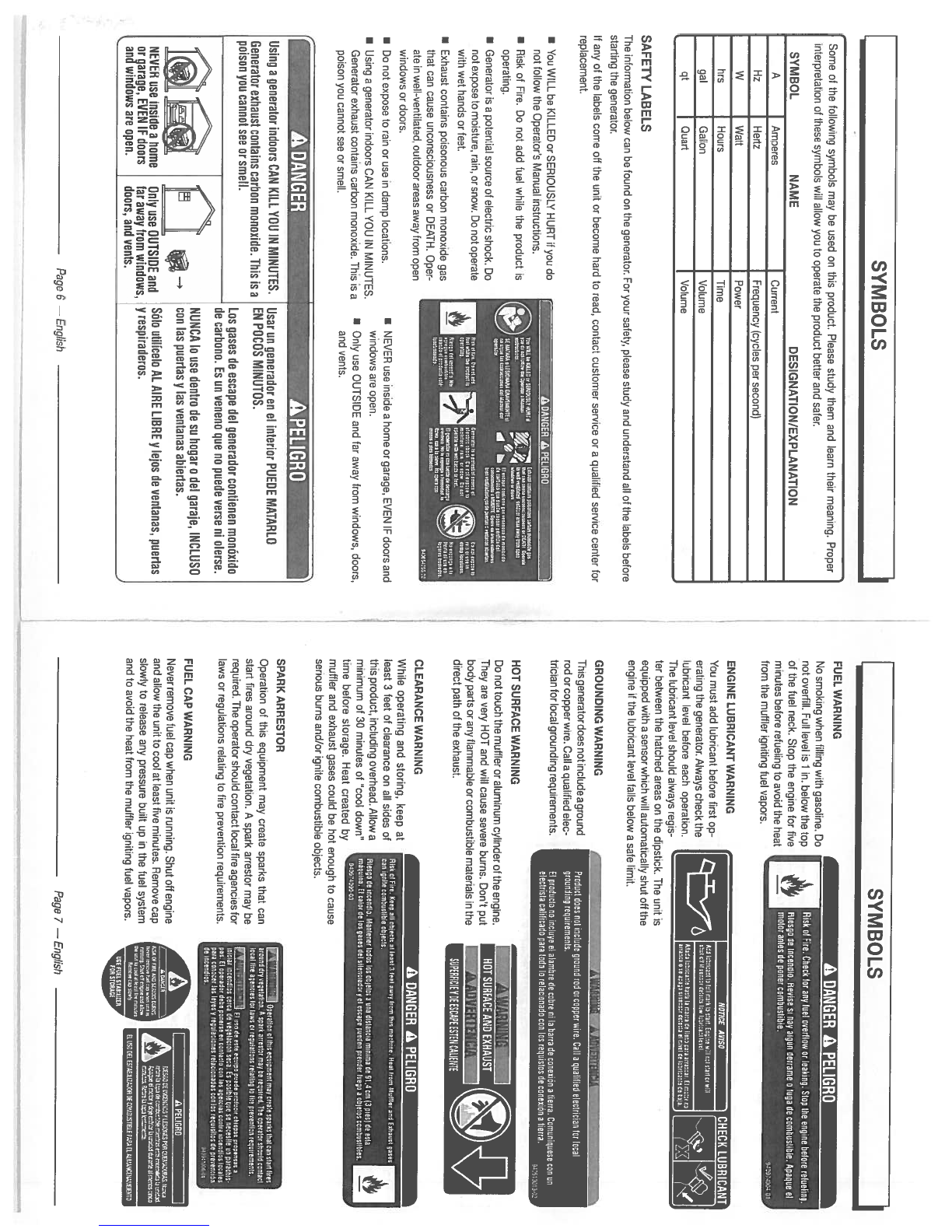
FUEL
WARNING
No
smoking when
filling
with
gasoline.
Do
not
overfill.
Full
level
is
1
in.
below
the
top
of
the
fuel
neck.
Stop
the
engine
for
five
minutes
before
refueling
to
avoid
the
heat
—
from
the
muffler
igniting fuel
vapors.
ENGINE LUBRICANT WARNING
,
You
must add
lubricant
before
first
op-
a
erating
the
generator.
Always
check
the
A
lubricant
level
before
each
operation.
The
lubricant
level
should
always
regis
ter
between
the
hatched
areas
on
the
dipstick.
The
unit
is
equipped
with a
sensor
which
will
automatically
shutoff
the
engine
if
the
lubricant
level
falls
below
a
safe
limit.
GROUNDING
WARNING
This
generator
does
notincludeaground
rod
or
copper
wire.
Call
a
qualified
elec
trician for local
grounding
requirements.
H
OT
SUR
FACE
WARN
ING
Do
not
touch
the
muffler
or
aluminum
cylinder
of
the
engine.
They
are
very
HOT
and
will
cause
severe
burns.
Don’t
put
body
parts
or
any
flammable
or
combustible
materials
in
the
direct path
of
the
exhaust.
CLEARANCE
WARNING
While
operating
and
storing, keep
at
least
3
feet
of
clearance
on
all
sides
ot
this
product,
including
overhead.
Allow
a
minimum
of
30
minutes
of
“cool
down”
time
before
storage.
Heat
created
by
muffler
and
exhaust
gases
could
be
hot
enough
to
cause
serious
burns
and/or
ignite
combustible
objects.
SPARK
ARRESTOR
Operation
of
this
equipment
may
create sparks
that
can
start
fires
around
dry
vegetation.
A
spark arrestor
may
be
required.
The
operator
should
contact
local
tire
agencies
for
laws
or
regulations
relating
to
tire
prevention
requirements.
FUEL
CAP WARNING
Never
remove
fuel
cap
when
unit
is
running.
Shut
off
engine
and
allow
the
unit
to
cool at
least
five
minutes. Remove
cap
slowly
to
release
any
pressure
built
up
in
the
fuel
system
and
to avoid
the
heat
from
the
muffler
igniting
fuel
vapors.
Page
6
—
English
Page
7
—
English
SYMBOLS
I
SYMBOL
NAME
Some
of
the
following
symbols
may
be
used
on
this
product.
Please
study
them and
learn
their meaning.
Proper
interpretation
of
these
symbols
will
allow
you
to
operate
the
product
better
and
safer.
DESIGNATION/EXPLANATION
A
Amperes
Current
Hz
Hertz
Frequency
(cycles
per
second(
W
Watt
Power
hrs
Hours
Time
gal
Gallon Volume
qt
Ouaff
Volume
SYMBOLS
A
DANGER
A
PEUGRO
SAFETY
LABELS
The
information
below
can
be found
on
the
generator.
For
your safety,
please
study
and
understand
all
of
the
labels
before
staffing
the
generator.
If
any
of
the labels
come
off
the
unit
or
become
hard to
read,
contact customer
service
or
a
qualified
service
center
for
replacement.
Add
Aiolm.l
wAdE
11Aw1.
cafeS
ci
thd
o,
will
diAl
dM0000
44th
ci
441aM lied.
Mad.
cikath
lath
S
maccaP
doma
p.m
warn,,
El
mediom
Irnaca
000441
A
olmer
HAM.
.1
A,IH
AickAn
4
HØ.
InI
-
AWAWSTaVERThcA
LSi77
Pro
Wict
does
aol
bKbtdo greond
rod
or
copper
wire.
Call
a
qealllled electrician
for
local
groottdlnq
roqoiremoots.
El
pradoffo
no
loclsyo
ol
alambro
do
coke
ella
barn
do
canceled
a
Horn.
Coreanlqaou
coo
in
oloclrista caliticado
pan
teds
In
nelxtonado
con
In
roqoistos
do
conoolde
a
bonn.
•
NEVER
use
inside
a
home
or
garage,
EVEN
IF
doors
and
windows
are
open.
I
Only
use
OUTSIDE
and
far
away
from
windows,
doors,
and
vents.
A
DANGER
APEUGRO
HOT
SURFACE AND
EXHAUST
SUPt1IUEfDEESCAP!ESTEN
CRIONTE
Using
a
generator
indoors
CAN
KILL YOU
IN
MINUTES.
Usar
on
generador
en
el
interior
PUEDE
MATARLO
Generator
exhaust
Contains
carhon monoxide.
This
is
a
EN
POCOS
MINUTOS.
poison
you
Cannot
see
or
smell.
Los
gases
de
escape
del
generador
contienen
monoxido
de
carhono.
Es on
veneno
que
no
puede
verse
ni
olerse.
NUNCA
lo
use dentro
de
so
hogar
o
del
garaje,
INCLUSO
.
.
—
con
las
puertas
y
las
ventanas
ahiertas.
NEVER
use inside
a
home
Only
use
OUTSIDE
and
SOlo
utilicelo
AL
AIRE LIBRE
y
lejos
de
ventanas,
puertas
or
garage,
EVEN
IF
doors
tar
away
from
windows,
y
respiraderos.
and
windows
are open. doors,
and
vents.
A
DANGER
A
PEUGRO
ebb
.1
FIre.
Coop
.11
objects
at
lead
3
tool
away
tram
mo
macirma.
teat
Iron
Mettor
and
Extant
oasis
con
fl
mmbeatbto
*0db.
010000
A
tncowdte.
Mactree
teAs
too
obtebre
a
ire
dieaocio
minim,
do
01,0
an
tO
plant
do
cola
mdoetno.
El
cater
A
lea
pore
dot
atbactadory
ot
mcape
peAce
podior
tuqo
a
Ajetre
mmmdl
Woo.
9900140ea43
Yil.’.::JIopeoattaaotodooqotpcr,ontreycmatoaparutmatmnotodhnoa
ceased
ioyvatatat%e.
0
opwt
amoober may
Ad
mqefrod.
TAO
operator obreld
contact
local
Am
.ooclaa
tan
laws
an
moeletlan
mbtlae
to
tim
pmnootoe roqotremeob.
Vt”i’,ntt;
TI
At
usA
iota
oqotpepcda
padoclrchiapacompoocaoa
taker
teroodtre
mica
A
aoqabddo mix.
La
pablo
qua
so oocoalto ac
paracNlo
pa.
El
opoadoo
Abe
peno
om
coobdo
an
lao
oqoactao
contra
tem*aa
scald
p.m
madder
too
kymy
mptldGrre
natacteoadre
no
too
mqatsbba
A
pravaoddo
A
beaus..
/
a—,’
rmomaMMAnamosecc
lwom,.aeauctomac
,wrn.iWicrnww.dHA
aoacwwddldoom,44.
0-a-c—A.
APaIGon
tk
anoooroanarimmcman
new*wawMtnalaa
Ate
i’d
Ad
S
doicd
AHA
d
cr000
di
fl44oAt4il44
———-
‘“-,ea’cr...
.
------
ELECTRICAL
ELECTRICAL
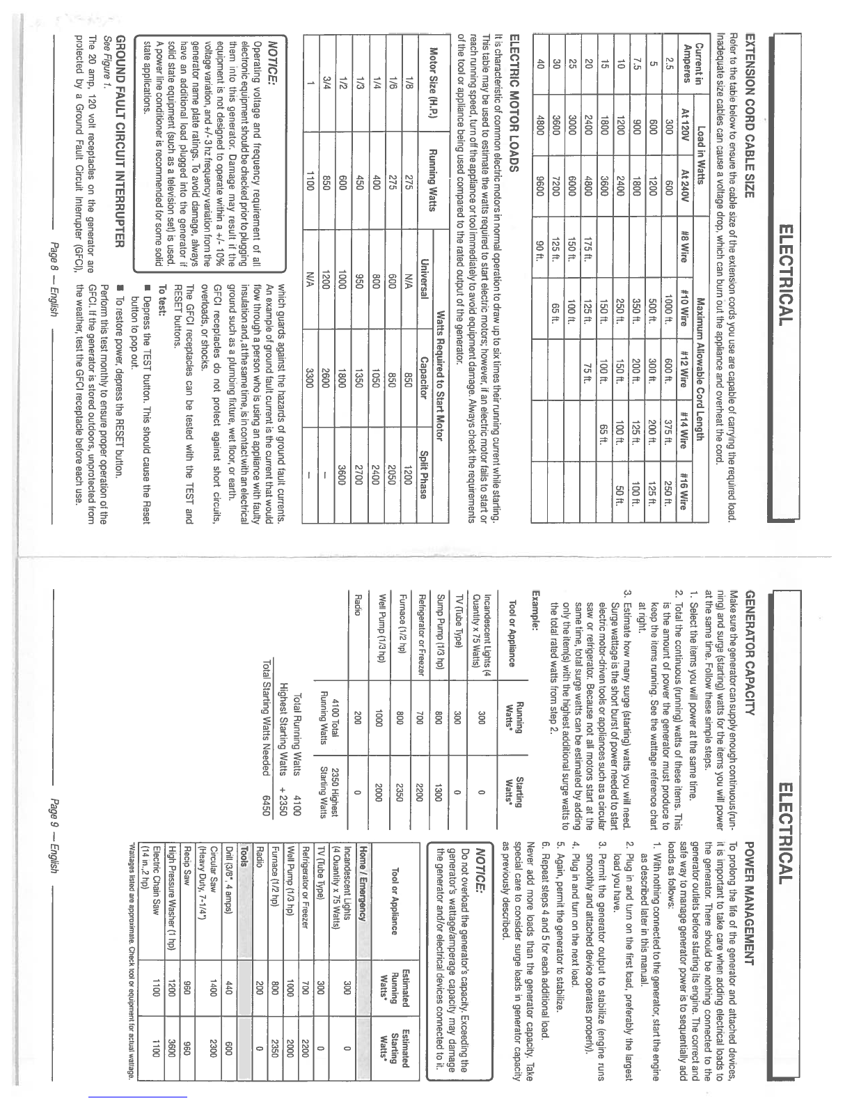
GROUND
FAULT
CIRCUIT INTERRUPTER
See
Figure
7.
The
20
amp,
120
volt
receptacles
on
the
generator
are
protected
by
a
Ground
Fault Circuit
Interrupter
(GFCI),
which
guards against
the
hazards
of
ground
fault
currents.
An
example
of
ground
fault
current
is
the
current
that
would
flow
through
a
person
who
is
using
an
appliance
with
faulty
insulation
and,
atthesametime,
is
in
contactwith
an
electrical
ground
such
as
a
plumbing
fixture,
wet
floor,
or
earth.
GFCI
receptacles
do
not
protect
against
short
circuits,
overloads,
or
shocks.
The
GFCI
receptacles
can
be
tested
with
the
TEST
and
RESET
buttons,
To
test:
•
Depress
the
TEST
button.
This
should
cause
the
Reset
button
to
pop
out.
•
To
restore
power,
depress
the
RESET
button.
Pertorm
this
test
monthly
to
ensure
proper
operation
of
the
GFCI.
If
the
generator
is
stored
outdoors,
unprotected
from
the
weather,
test
the
GFCI
receptacle
before
each
use.
GENERATOR
CAPACITY
Make
sure the
generator
can
supply
enough
continuous
(run
ning)
and
surge
(starting)
watts
for
the
items
you
will
power
at
the
same
time.
Follow
these
simple
steps.
1.
Select
the
items
you
will
power at
the
same
time.
2.
Total
the
continuous
(running)
watts
of
these
items.
This
is
the
amount
of
power the
generator
must
produce
to
keep
the items
running.
See
the
wattage
reference chart
at
right.
3.
Estimate
how
many
surge
(starting)
watts
you
will
need.
Surge
wattage
is
the short burst
of
power
needed
to
start
electric motor-driven
tools
or
appliances such as
a
circular
saw
or
refrigerator.
Because
not
all
motors
start
at
the
same
time, total
surge
watts
can
be
estimated
by
adding
only
the
item(s)
with
the
highest
additional
surge
watts
to
the
total
rated
watts
from
step
2.
Example:
Incandescent
Lights
(4
300
0
Quantity
x
75
Wattsl
WtTubeType(
300
0
Sump
Pump
11/3
hp)
800 1300
Refrigerator
or
Freezer
700
2200
Furnace
11/2
hp)
800
2350
Weil
Pump
11/3
hp)
1000
2000
Radio
200
0
POWER
MANAGEMENT
To
prolong
the
life
of
the generator
and
attached
devices,
it
is
important
to
take
care
when
adding
electrical
loads
to
the
generator.
There
should
be
nothing
connected
to
the
generator
outlets before starting
its
engine.
The
correct
and
safe
way
to
manage generator
power
is
to
sequentially
add
loads as
follows:
1.
With
nothing
connected
to
the
generator,
start
the engine
as
described
later
in
this
manual.
2.
Plug
in
and
turn
on
the
first
load,
preferably
the
largest
load
you
have.
3.
Permit
the
generator
output
to
stabilize
(engine
runs
smoothly
and
attached
device
operates
properly).
4.
Plug
in
and
turn
on
the
next
load.
5.
Again,
permit
the
generator
to
stabilize.
6.
Repeat
steps
4
and
5
for
each
additional
load.
Estimated
Estimated
Tool
or
Appliance
Running
Starting
Watts’
Wafts’
Home
I
Emergency
Incandescent
Lights
300
0
(4
Quantity
x
75
Watts)
WlTube
Type)
300
0
Refrigerator
or
Freezer
700
2200
Weli
Pump
(1)3 hp)
1000
2000
Furnace
(1/2
hp)
800
2350
Radio
200
0
Tools
Drill
(3/8”.
4
amps)
440 600
Circular
Saw
1400
2300
(Heavy
Duty,
7-1/4”)
Recip Saw 960
960
High
Pressure
Washer
(1
hp(
1200
3600
Electric Chain
Saw 1100 1100
(14
in.,2 hp)
EXTENSION
CORD
CABLE
SIZE
Refer
to
the table
below
to
ensure
the
cable
size
of
the extension
cords
you
use
are
capable
of
carrying
the
required
load.
Inadequate
size
cables
can
cause
avoltage
drop,
which
can
burn out
the
appliance
and
overheat
the
cord.
Current
in
Load
in
Watts
Maximum
Allowable
Cord
Length
Amperes
At
120V
At
240V
#8
Wire #10
Wire #12
Wire
-
#14 Wire #16 Wire
2.5
300
600 1000
ft.
600
ft.
375
ft.
250
ft.
5
600 1200 500
ft.
300
ft.
200
ft.
125
ft.
7.5 900
1800
350
ft.
200
ft.
125
ft.
100
ft.
10
1200
2400
250ff.
150
ft.
100
ft.
50ft.
15
1800
3600
150
ft.
100
ft.
65ft.
20
2400 4800
175
ft.
125
ft.
75ft.
25
3000 6000
150
ft.
100
ft.
30
3600
7200
125
ft.
65ft.
40
4800
9600
90ft.
ELECTRIC MOTOR
LOADS
It
is
characteristic
of
common
electric
motors
in
normal
operation
to
draw
up
to
six
times
their
running
current
while
starting.
This
table
may
be
used
to
estimate
the
watts
required
to
start
electric
motors;
however,
if
an
electric motor
fails
to
start
or
reach
running
speed,
turn
oft
the
appliance
or
tool
immediately
to
avoid
equipment
damage.
Always
check
the requirements
of
the
tool or
appliance
being
used
compared
to
the
rated
output
of
the
generator.
Running
Tool
or
Appliance
Watts’
..
Watts Required
to
Start
Motor
Motor
Size
(H.R)
Running
Watts
Universal
Capacitor
Split
Phase
1/8
275
N/A
850 1200
1/6
275 600 850
2050
1/4
400
800 1050
2400
1/3
450 950 1350
2700
1/2
600 1000
1800
3600
3/4
850
1200
2600
—
1
1100
N/A
3300
—
Never
add
mote
loads
than
the
generator
capacity.
Take
Starting
special
care
to
consider
surge loads
in
generator
capacity
Watts’
as
previously
described.
NOTICE:
Do
not
overload
the generator’s
capacity.
Exceeding
the
generator’s
wattage/amperage
capacity
may
damage
the generator and/or
electrical
devices
connected
to
it.
NOTICE:
Operating
voltage and
frequency requirement
of
all
electronic
equipment
should be
checked
prior
to
plugging
them
into
this
generator.
Damage
may
result
if
the
equipment
is
not
designed
to
operate
within
a
+/-
10%
voltage
variation,
and
+/-
3hz
frequency
variation
from
the
generator
name plate
ratings.
To
avoid
damage,
always
have
an
additional
load
plugged
into
the
generator
if
solid
state
equipment
(such
as
a
television set)
is
used.
A
power
line
conditioner
is
recommended
for
some
solid
state
applications.
4100
Total
Running
Watts
2350
Highest
Starting Watts
Total
Running
Watts 4100
Highest
Starting
Watts
÷
2350
Total
Starting Watts
Needed
6450
‘Waitageshuted
are
approximate.
cheuk
lost
or
equipme,,t
for
actuai
watiage.
Page
8
—
English
Page
9
—
English

PRODUCT
SPECIFICATIONS
ENGINE
Engine
Type
420cc
OHV,
Air
Cooled
Overhead
Valve
Replacement
Spark
Plug
Torch,
LG
F7TC, or
equivalent
Engine
Lubricant
Volume
approximately
37
oz.
Fuel
Volume
6
gal.
Rated
running
watts
determined
by
PGMA
Standard
0300
KNOW
YOUR
GENERATOR
See
Figure
2.
The
safe
use
of
this
product
requires
an
understanding
of
the
information
on
the
product
and
in
this
operator’s
manual
as
well
as
a
knowledge
of
the
project
you
are
attempting.
Before
use
of
this
product,
familiarize
yourself
with
all
operating
features
and safety
rules.
AC
CIRCUIT
BREAKERS
The
circuit
breakers
are provided
to
protect
the
generator
against
electrical
overload.
The
circuit
breaker
may
be
reset
by
pressing
the
circuit
breaker
reset
button.
MR
FILTER
The
air
filter
helps
to
limit
the amount
of
dirt
and
dust
drawn
into
the
unit
during
operation.
CHOKE
LEVER
The
choke
lever
is
used
when starting
the
engine.
FUEL
TANK
The
fuel
tank has
a
capacity
of
6
gallons.
FUEL
VALVE
Fuel
flow
trom
the
fuel
tank
to
the
engine
is
turned
on
and
off
using
the
fuel
valve.
LOW
OIL
SHUT
DOWN
PROTECTOR
The
low
oil
sensor
causes
the
engine
to
stop
if
the
level of
lubricant
in
the
crankcase
is
insufficient.
OIL
CAP/DIPSTICK
Remove
the
oil
fill
cap
to
check
and
add
lubricant
to
the
generator
when
necessary.
OIL DRAIN
PLUG
When
changing the
engine
lubricant,
unscrew
and remove
the
oil
drain
plug
to
allow
old
engine
lubricant
to
be
drained.
RECEPTACLES
Your
generator
has
the
following
single
phase,
60Hz
outlets:
one
240
Volt
AC
30 Amp
twist
lock
receptacle
and
two
120
Volt
AC,
20
Amp
duplex
GFCI
receptacles.
These can be
used
toroperating
appropriate appliances,
electrical
lighting,
tools, and
motor
loads.
RECOIL
STARTER
GRIP
The
recoil
starter
grip
is
used
to
start the generator’s
engine.
STOP
SWITCH
The
generator
has
a
stop
switch
near
the
fuel
valve.
To
turn
the
engine
off,
press
and
hold
the
STOP
switch
until
the
engine
stops.
UNPACKING
This
product
requires
assembly.
•
Carefully
cut
the
box down
the
sides
then remove
the
machine
and
any
accessories
from
the
box.
Make
sure
that
all
items
listed
in
the
loose
parts
list
are
included.
NOTE:
This
machine
is
heavy
and requires
a
minimum
of
two
people
to
lift.
To
avoid
back
injury,
lift
with
your
legs
and
not your
back.
•
Inspect
the
unit
carefully
to
make
sure
no
damage
occurred
during
shipping.
•
Do
not
discard
the
packing
material
until
you
have
carefully
inspected
and
satisfactorily
operated
the
product.
•
If
any
parts
are
damaged
or
missing,
please
call
1-800-726-5760
for
assistance.
LOOSE
PARTS
LIST
See
Figure
3
The
following
items are
included
with
the
generator:
Description
Qty.
Axle
2
Wheel
2
Washer
2
4
Hitch
Pin
2
5
Bolt
2
6
Rubber
Foot
2
7
Lock
Nut
2
8
Bottle
of
Engine
Lubricant
1
Operator’s
Manual
(not
shown)
1
TOOLS
NEEDED
See
Figure
4.
The
following
tools
(not
included
or
drawn
to
scale) are
needed
for
assembly:
•
Socket
Wrenches
•
Adjustable
Wrench
NOTE:
Do
not put
fuel or
lubricant
in
the
generator
before
installing
the feet
and
wheels.
INSTALLING
FEET
See
Figure
5.
•
Locate the
following
items:
2
rubber
feet
2
lock
nuts
2
bolts
•
Insert bolt
through
rubber
foot,
then
through frame
as
shown.
•
Thread
lock nut
onto
bolt
and
tighten
one
full
turn
past
snug.
NOTE:
Be
careful not
to
overtighten
so
that
foot
material
collapses.
•
Repeat
with
remaining
foot.
FEATURES
GENERATOR
Rated
Voltage
120V/240V
Rated
Amps
45.8A
/
22.9A
Rated
Running
Watts*
5,500W
Rated
Starting Watts
6,875W
Rated Frequency
60
Hz
ASSEMBLY
Key
No.
2
3
A
WARNING:
Do
not
use
this
product
if
any
parts
on
the
Loose
Parts
List
are already
assembled
to
your
product
when
you
unpack
it.
Parts
on
this
list
are
not
assembled
to
the
product
by
the
manufacturer
and
require
customer
installation.
Use
of
a
product that
may
have
been
improperly
assembled
could
result
in
serious
personal
injury.
GROUND
TERMINAL
The
ground
terminal
is
used
to
assist
in
properly
grounding
the
generatorto
help
protect
againstelect
rical
shock.
Consult
with
a
local
qualified
electrician
for
grounding
requirements
in
your
area.
A
WARNING:
If
any
parts
are
damaged
or
missing
do
not
operate
this
product
until
the
parts
are
replaced.
Use
of
this
product
with
damaged
or
missing
parts
could
result
in
serious
personal
injury.
A
WARNING:
Do
not
attempt
to
modify
this
product
or
create
acces
sories
not
recommended
for
use
with
this
product.
Any
such
alteration
or
modification
is
misuse and
could
result
in
a
hazardous
condition
leading
to
possible
serious
personal
injury.
A
WARNING:
Do
not
attempt
to
operate
the
generator
until
assembly
is
complete.
Failure to
comply could
result
in
possible
serious personal
injury.
Page
10
—
English
Page
II
—English

A
DANGER:
Carbon
Monoxide.
Using a
generator
indoors
CAN
KILL
YOU
IN
MINUTES.
Generator
exhaust
contains
high
levels
of
carbon
mon
oxide
(CC),
a
poisonous gas
you
cannot
see
or
smell.
If
you
can
smell
the
generator
exhaust,
you
are
breathing
CO. But
even
if
you
cannot
smell
the
exhaust,
you
could
be breathing
CO.
•
Never
use
a
generator
inside
homes,
garages,
crawl
spaces,
or
other
partly
enclosed
areas.
Deadly levels
of
carbon
monoxide
can
build
up
in
these
areas.
Us
ing
a
fan
or
opening
windows
and
doors
does
NOT
supply
enough
fresh
air.
•
ONLY
use
a
generator outdoors
and
far
away
from
open
windows,
doors,
and
vents.
These
openings
can
pull
in
generator
exhaust.
Even
when
you
use
a
generator
correctly,
CO
may
leak
into
the
home.
ALWAYS
use
a
battery-powered
or
battery-
backup
CO
alarm
in
the
home.
If
you
start
to
feel
sick,
dizzy,
or
weak
after
the
generator
has
been
running,
move
to
fresh
air
RIGHT
AWAY.
See
a
doctor.
You
could have
carbon
monoxide poisoning.
APPLICATIONS
This
generator
is
designed
to
supply electrical
power
for
operating compatible
electrical
lighting,
appliances,
tools,
and motor loads.
BEFORE
OPERATING
THE
UNIT
•
Only
use
OUTSIDE
and at
least
20
feet
away
from
win
dows,
doors,
and
vents
as
recommended
by
the
U.S
Department
of
Health
and
Human
Services Centers
for
Disease
Control
and
Prevention.
Your
specific home
and/
or wind
conditions
may
require
additional
distance.
•
NEVER
use
inside
a
home
or
garage,
EVEN
IF
doors
and
windows
are
open.
•
Always
position
the
generator
on
a
flat
firm
surface.
SPECIAL
REQUIREMENTS:
There
may
be General or
State
Occupational
Safety and
Health
Administration
(OSHA)
regulations,
local
codes
or
ordinances
that
apply
to
the
intended
use
of
the
generator.
Please consult
a
qualified
electrician, electrical
inspector,
or
the
local
agency
having
jurisdiction:
•
In
some
areas,
generators
are required
to
be
registered
with
local
utility
companies.
•
If
the
generator
is
used
at
a
construction
site,
there
may
be additional
regulations
which
must
be
observed.
RAISING
AND
LOWERING
THE HANDLE
See
Figure
7-8.
•
To
raise
the
handle
(for
moving
the
generator):
pull
the
handle
up
until
the
handle
release
knob
snaps
into
lock
ing
position
and
insert
the
handle
lock
pin
to
secure
the
handle
in
place.
U
To
lower
the
handle
(for
storing
or
transporting
the
gen
erator):
remove
the
handle
lock
pin,
then
pull
the handle
release
knob
out and
lower
the
handle
to
the
down
posi
tion.
CHECKING/ADDING
LUBRICANT
See
Figure
9.
NOTE:
If
a
separate
engine manual
is
provided
forthis product,
please
follow
the instructions
provided
in
the
engine
manual
instead
of
the
information
listed below.
Engine
lubricant
has
a
major influence
on
engine
perfor
mance
and
service
life.
For
general,
all-temperature
use,
SAE
10W-3D
is
recommended.
Always
use
a
4-stroke
motor
lubricant
that
meets
or
exceeds
the requirements
for
API
service
classification
5].
This
engine
comes
with
a
feature
that
will
shutoff
the engine
when
a
specific
lubricant
level
is
not maintained.
The
engine
will
not
restart
until
an
appropriate
lubricant
level
is
reached.
NOTE:
Non-detergent
or
2-stroke
engine
lubricants
will
damage
the
engine and should
not
be
used.
I
Unscrew
the
oil
cap/dipstick
and
remove.
•
Wipe
dipstick
clean and
re-seat
in
hole;
do
not
rethread.
•
Remove
dipstick
again and
check
lubricant
level.
Lubri
cant
level
should
fall
between
the
hatched
areas
on
the
dipstick.
•
If
level
is
low,
add
engine
lubricant
until
the
fluid
level
rises
to
the upper
portion
of
the
dipstick.
•
Replace
and
secure
the
oil
cap/dipstick.
USING FUEL STABILIZER
Fuel
gets
old,
oxidizes, and
breaks
down over
time.
Adding
a
fuel
stabilizer
(not
included)
extends
the
usable
life
of
fuel
and
helps prevent
deposits
from
forming
that can
clog
the
fuel
system.
Follow
fuel
stabilizer manufacturer’s
directions
for
correct
ratio
of
stabilizer
to
fuel.
•
Mix
fuel
stabilizer and
gasoline
prior
to
filling
the
tank
by
using
a
gas
can
or
other
approved
fuel
container
and
shaking
gently
to
combine.
NOTE:
To
control
the amount
of fuel
stabilizer
being
add
ed
to
the
engine,
always
mix
fuel
stabilizer
with
gasoline
before
fueling
the
tank
rather than adding
fuel
stabilizer
directly
into
the
generator’s
fuel
tank.
•
Replace
and
secure
the
fuel
tank
cap.
•
Start and
run
the
engine
for
at
least
5
minutes
to
allo
stabilizer
to
treat
the
entire
fuel
system.
Page
12
—
English
Page
13
—
English
ASSEMBLY
INSTALLING
THE
WHEELS
I
Raise
the
end
of
the
generator opposite
the
recoil
starter
See
Figure
6.
high
enough
to
gain
access
to
the
frame
bottom;
securely
Wheels
are provided
to
assist
in
moving
the
generator
to
position
props
underneath
to
support.
the desired
location
and
should be
installed
on
the
same
U
Insert axle
through
the
center
of
the
wheel.
side
as
the
handle.
I
Place
washer
on
axle
and
then
slide
the
axle
through
the
U
Locate
the
following
items:
bracket
on
the
frame.
2
axles
•
Push
the
hitch
pin
into
the
hole
on
the
end
of
the
axle
to
2
wheels
secure
the
wheel
assembly.
2
washers
NOTE:
The
hitch
pin
should
be
pushed
into
the
axle
until
the
center
of
the
pin
tests
on
top
of
the
axle.
2
hitch
pins
•
Repeat the
process
on
the
other
side.
OPERATION
OPERATION
A
WARNING:
Do
not
allow
familiarity with
this
product
to
make
you
careless.
Remember that
a
careless
fraction
of
a
second
is
sufficient to
inflict
serious
injury.
A
WARNING:
Do
not
use
any
attachments
or
accessories
not
recom
mended
by
the
manufacturer
of
this
product.
The
use
of
attachments
or
accessories
not
recommended
can
result
in
serious personal
injury.
NOTICE:
This
product
is
equipped
with a
spark
arrestor that
has
been
evaluated
by
the
USDA
Forest Service;
however,
product
users
must
comply
with
Federal,
State,
and
local
fire
prevention regulations.
Check
with
appropriate
au
thorities.
Contact
customer
service
or
a
qualified
service
center
to
purchase
a
replacement
spark
arrestor.
A
CAUTION:
Do
not
attempt
to
lift
the
unit
by
the handle assembly.
If
it
is
necessary
to
lift
the
generator,
always
grasp
by
the
frame.
Use
proper
lifting
techniques
to
avoid
back
injury.
A
WARNING:
If
this
generator
will
be
used
only
with
cord
and
plug-
connected
equipment,
National Electric
Code
does
not
require
that
the
unit
be
grounded.
However,
other
methods
of
using
the
generator
may require
grounding
to
reduce
the
risk
of
shock
or
electrocution.
Consult
a
qualified
electrician, electrical inspector,
or local
agency
having
jurisdiction
for local
codes
or
ordinances
to
find
out
if
grounding
is
needed
in
your
situation before
using
the
generator.
NOTICE:
Before
each
use,
inspect
the
entire
product
for
damaged,
missing,
or
loose
parts such as screws,
nuts,
bolts,
caps,
etc.
Tighten
securely
all
fasteners
and
caps
and
do
not
operate
this
product
until
all
missing
or
damaged
parts
are
replaced.
Please
contact
customer
service
or
a
qualified
service
center
for
assistance.
ETHANOL-BLENDED
FUELS
NOTICE:
Attempting
to
start
the
engine before
it
has
been
properly
filled
with
lubricant
will
result
in
equipment
failure.
NOTICE:
Do
not
use
E15
or
E85
fuel
in
this
product.
It
is
a
viola
tion
of
federal
law
and
will
damage
the
unit
and
void
your
warranty.
Only
use
unleaded
gasoline
containing
up
to
10%
ethanol.
-
—:-——.
- -
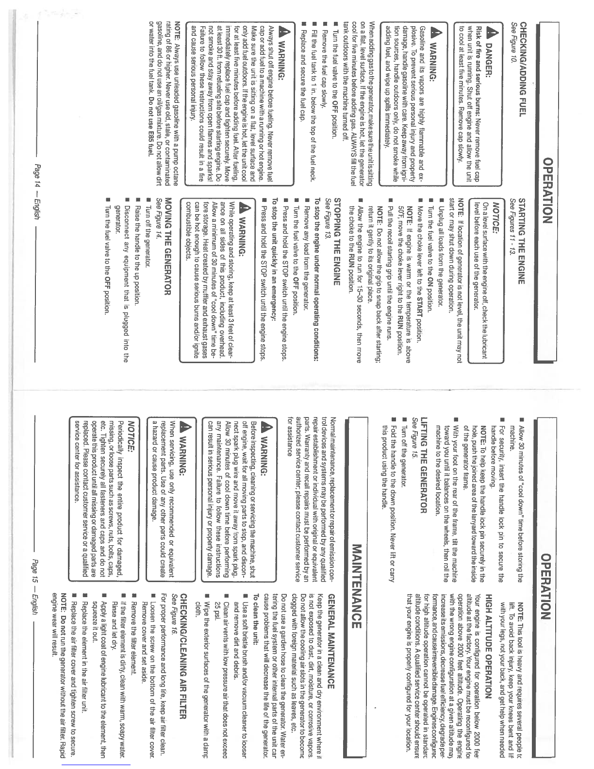
CHECKING/ADDING
FUEL
See
Figure
70.
When
adding
gas
to
the
generator, make
sure
the
unit
is
sitting
on a
flat,
level
surface,
lithe
engine
is
hot,
let
the
generator
cool
for
five
minutes
before adding
gas.
ALWAYS
fill
the
fuel
tank
outdoors
with
the machine turned
off.
•
Turn
the
fuel
valve
to
the
OFF
position.
•
Remove
the
fuel
cap
slowly.
I
Fill
the
fuel
tank
to
1
in.
below
the
top
of
the
fuel
neck.
•
Replace
and
secure
the
fuel
cap.
NOTE:
Always
use
unleaded
gasoline
with
a
pump
octane
rating
of
86
or
higher.
Never
use
old,
stale,
or
contaminated
gasoline,
and
do
not
use
an
oil/gas
mixture.
Do
not
allow
dirt
or
water
into
the
fuel
tank.
Do
not
use
E85
fuel.
STARTING
THE ENGINE
See
Figures
11
-
13.
NOTICE:
On
a
level
surface
with
the
engine
off,
check the
lubricant
level
before
each use
of
the
generator.
NOTE:
If
location
of
generator
is
not
level,
the
unit
may not
start
or
may
shut
down
during
operation.
•
Unplug
all
loads
from
the
generator.
a
Turn
the
fuel
valve
to
the
ON
position.
•
Move
the choke
lever
left
to
the
START
position.
NOTE:
If
engine
is
warm
or
the
temperature
is
above
50’F,
move
the
choke
lever
right to
the
RUN
position.
a
Pull
the
recoil
starting
grip
until
the
engine
runs.
NOTE:
Do
not
allow
the
grip
to
snap
back
after starting;
return
it
gently to
its
original
place.
a
Allow
the
engine
to
run
for
15—30
seconds,
then
move
the
choke
to
the
RUN
position.
STOPPING
THE ENGINE
See
Figure
13.
To
stop
the
engine
under
normal
operating
conditions:
I
Remove
any
load
from
the
generator.
I
Turn
the
fuel
valve
to
the
OFF
position.
I
Press
and
hold
the
STOP
switch
until
the
engine
stops.
To
stop
the
unit
quickly
in
an
emergency:
a
Press
and
hold
the
STOP
switch
until
the
engine
stops.
GENERAL
MAINTENANCE
Keep
the
generator
in
a
clean and
dry
environment
where
il
is
not
exposed
to
dust,
dirt,
moisture,
or
corrosive
vapors
Do
not
allow
the
cooling
air
slots
in
the
generator
to
become
clogged
with
foreign
material
such
as
leaves, etc.
Do
not
use
a
garden
hose
to
clean
the
generator.
Water
en
tering
the
fuel
system
or
other
internal
parts
of
the
unit
car
cause
problems
that
will
decrease
the
life
of
the
generator.
To
clean
the
unit:
a
Use
a
soft
bristle
brush
and/or
vacuum
cleaner
to
looser
and
remove
dirt
and
debris.
a
Clean
air
vents
with
low
pressure
air
that
does
not
exceec
25
psi.
a
Wipe
the
exterior
surfaces
of
the
generator
with
a
damp
cloth.
CHECKING/CLEANING
AIR
FILTER
See
Figure
16.
For
proper performance
and
long
life,
keep
air
filter
clean.
•
Loosen
the screw
on
the bottom
of
the
air filter
cover.
Remove
cover
and
set
aside.
•
Remove the
filter
element.
•
If
the
filter
element
is
dirty,
clean
with
warm,
soapy
water.
Rinse
and
let
dry.
a
Apply a
light
coat
of
engine
lubricant to
the
element, then
squeeze
it
out.
I
Replace
the element
in
the
air
filter
unit.
•
Replace the
air
filter
cover
and
tighten screw
to
secure.
NOTE: Do
not
run
the
generator
without
the
air
filter.
Rapid
engine
wear
will
result.
OPERATION
I
A
DANGER:
Risk
of
fire
and serious
burns:
Never
remove
fuel
cap
when
unit
is
running.
Shut
off
engine end
allow
the
unit
to
cool
at
least
five
minutes.
Remove
cap
slowly.
A
WARNING:
Gasoline
and
its
vapors
are
highly
flammable and
ex
plosive.
To
prevent
serious
personal
inlury
and
property
damage,
handle
gasoline
with
care.
Keep
away
from
igni
tion
sources,
handle
outdoors
only,
do
not
smoke
while
adding
fuel,
and wipe
up spills
immediately.
OPERATION
I
Allow
30
minutes
of
cool down” time
before
storing
the
NOTE: This
tool
is
heavy
and requires several
people
tc
machine,
lift.
To
avoid
back
injury,
keep
your
knees
bent
and
lit
a
For
security,
insert
the handle
lock
pin
to
secure
the
with
your legs, not your
back, and
get
help
when
needed
handle
before
moving.
HIGH
ALTITUDE
OPERATION
NOTE:
To
help
keep
the
handle
lock pin
securely
in
the
Your
engine
is
configured
for
operation
below
2000
fee
hole,
push
the
joined
area
of
the
lanyard
toward
the
inside
altitude
at
the
factory.
Your
engine
must
be
reconfigured
foi
of
the
generator
frame.
operation above
2000
feet
altitude. Operating
the
engine
•
With
your
foot
on
the
rear
of
the
frame,
tilt
the
machine
with
the
wrong
engine
configuration
at
a
given
altitude
ma
toward
you
until
it
balances
on
the wheels,
then
roll
the
increaseitsemissions,decreasefuelefflciency,degradeper
machine
to
the desired
location. formance,
and
cause
irreversible
damage.
Engines
configurec
for
high
altitude
operation
cannot
be
operated
in
standarc
LIFTING
THE
GENERATOR
altitude
conditions.
A
qualified
service
center
should
ensure
See
Figure
15.
that
your
engine
is
properly
configured
for
your
location.
a
Turn off
the
generator.
a
Fold
the handle
to
the
down position.
Never
lift
or
carry
this
product
using
the
handle.
MAINTENANCE
A
WARNING:
Always
shut
off
engine
before
fueling.
Never
remove
fuel
cap
or
add
fuel
toe
machine
with
a
running
or
hot
engine.
Make
sure the
unit
is
sitting
on a
flat,
level
surface
and
only
add
fuel
outdoors,
lithe
engine
is
hot,
let
the
unit
cool
for
at
least
five
minutes
before adding
fuel.
After
fueling,
immediately
replace
fuel
cap
and
tighten
securely.
Move
at
least
30
ft.
from
refueling
site
before starting engine.
Do
not
smoke
and
stay
away
from
open
flames
and
sparksl
Failure
to
follow
these
instructions
could result
in
a
fire
and
cause
serious
personal
injury.
Normal
maintenance, replacement
or
repairof
emission
con
trol
devices
and
systems
may
be
performed
by
any
qualified
repair
establishment
or individual
with
original or
equivalent
parts.
Warranty
and
recall
repairs
must
be
performed
by
an
authorized service
center;
please
contact customer
service
for
assistance
A
WARNING:
While
operating
and
storing,
keep
at
least
3
feet
of
clear
ance
on
all
sides
of
this
product,
including
overhead.
Allow
a
minimum
of
30
minutes
of
“cool
down”
time
be
fore
storage.
Heat
created
by
muffler
and
exhaust
gases
can be
hot
enough
to
cause
serious
burns
and/or
ignite
combustible
objects.
A
WARNING:
Before
inspecting,
cleaning
orservicing
the machine,
shut
off
engine,
wait
for
all
moving
parts
to
stop,
and
discon
nect spark
plug
wire
and
move
it
away
from
spark
plug.
Allow
30
minutes
of
cool down time
before
performing
any
maintenance.
Failure
to
follow
these
instructions
can
result
in
serious personal
injury
or
property
damage.
MOVING
THE
GENERATOR
See
Figure
14.
•
Turn
off
the
generator.
a
Raise
the handle
to
the
up
position.
a
Disconnect
any
equipment
that
is
plugged
into
the
generator.
•
Turn
the
fuel
valve to
the
OFF
position.
A
WARNING:
When
servicing,
use
only
recommended
or
equivalent
replacement
parts.
Use
of
any
other
parts
could
create
a
hazard
or
cause
product
damage.
NOTICE:
Periodically
inspect the
entire
product
for
damaged,
missing,
or
loose
parts such as screws,
nuts, bolts,
caps,
etc.
Tighten
securely
all
fasteners
and
caps
and
do not
operate
this
product
until
all
missing
or
damaged
parts
are
replaced. Please
contact
customer
service
or
a
qualified
service
center
for
assistance.
Page
74
—
English
Page
15
—English
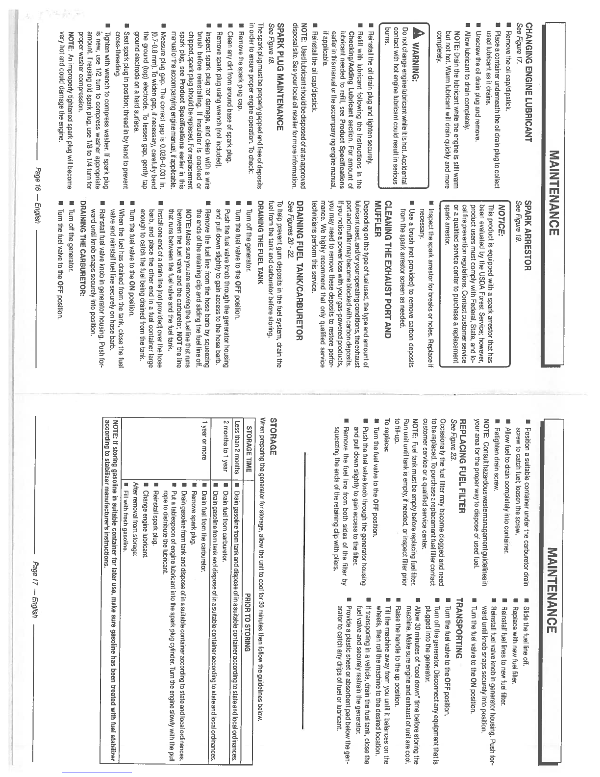
CHANGING ENGINE LUBRICANT
See
Figure
77.
•
Remove
the
oil
cap/dipstick.
I
Place
a
container
underneath the
oil
drain
plug
to
collect
used
lubricant
as
it
drains.
•
Unscrew
the
oil
drain
plug
and
remove.
•
Allow
lubricant
to
drain
completely.
NOTE:
Drain
the
lubricant
while
the
engine
is
still
warm
but not
hot. Warm
lubricant
will
drain
quickly
and
more
completely.
[A
WARNING:
Do
not
change
engine
lubricant
while
it
is
hot.
Accidental
contact
with
hot
engine
lubricant could
result
in
serious
burns.
•
Reinstall
the
oil
drain
plug
and
tighten
securely.
•
Refill
with
lubricant
following
the
instructions
in
the
Checking/Adding
Lubricant
section.
For
amount
of
lubricant
needed
to
refill,
see
Product Specifications
earlier
in
this
manual
or
the
accompanying
engine manual,
if
applicable.
a
Reinstall
the
oil
cap/dipstick.
NOTE:
Used
Iubricantshould
bedisposedof
atan
approved
disposal
site.
See
your
local
oil
retailer
for
more
information.
SPARK
PLUG MAINTENANCE
See
Figure
78.
The
spark
plug
must
be properly
gapped
and
free
of
deposits
in
order
to
ensure
proper
engine
operation.
To
check:
•
Remove
the spark
plug
cap.
a
Clean any
dirt
from
around
base
of
spark
plug.
•
Remove
spark
plug
using
wrench
(not
included).
•
Inspect spark
plug
for
damage,
and clean
with awire
brush before
reinstalling.
If
insulator
is
cracked
or
chipped, spark
plug
should be
replaced.
For
replacement
spark
plug,
see Product
Specifications
earlier
in
this
manual
or
the
accompanying
engine manual,
if
applicable.
•
Measure
plug
gap.
The
correct
gap
is
0.028—0.031
in.
(0.7-0.8
mm).
To
widen
gap,
if
necessary,
carefully
bend
the
ground
(top)
electrode.
To
lessen
gap,
gently
tap
ground
electrode
on a
hard
surface.
•
Seat
spark
plug
in
position;
thread
in
by
hand
to
prevent
cross-threading.
a
Tighten
with
wrench
to
compress
washer.
If
spark
plug
is
new,
use
1/2
turn
to
compress washer
appropriate
amount.
If
reusing
old
spark
plug,
use
1/8 to
1/4
turn
for
proper
washer
compression.
NOTE:
An
improperly
tightened spark
plug
will
become
very
hot and
could
damage
the engine.
SPARK ARRESTOR
See
Figure
19.
a
Inspect
the spark
arrestor
for
breaks
or
holes.
Replace
if
necessary.
a
Use
abrush
(not
provided) to
remove
carbon
deposits
from
the
spark
arrestor screen
as
needed.
CLEANING THE EXHAUST
PORT
AND
MUFFLER
Depending
on
the type
of
fuel
used,
the type
and
amount
of
lubricantused,
and/oryouroperating
conditions,
theexhaust
port
and
muffler
may
become
blocked
With
carbon
deposits.
If
you
notice
a
power
loss
with
your
gas-powered
products,
you
may
need
to
remove
these
deposits
to
restore
perfor
mance.
We
highly
recommend
that
only
qualified
service
technicians
perform
this
service.
DRAINING
FUEL
TANK/CARBURETOR
See
Figures
20-
22.
To
help
prevent
gum
deposits
in
the
fuel
system,
drain
the
fuel
from
the
tank and
carburetor
before
storing.
DRAINING
THE
FUEL
TANK
•
Turn
off
the
generator.
a
Turn
the
fuel
valve
to
the
OFF
position.
a
Push
the
fuel
valve
knob
through
the
generator
housing
and
pull
down
slightly
to
gain
access
to
the
hose
barb.
I
Remove
the
fuel
line
from
the
hose
barb
by
squeezing
the
ends
of
the
retaining
clip
and
sliding
the
fuel
line
off.
NOTE:
Make
sure
you
are
removing
the
fuel
line
that
runs
between
the
fuel
valve
and
the
carburetor,
NOT
the
line
that
runs
between
the
fuel
valve
and
the
fuel
tank.
a
Install
one end
of
a
drain
line
(not
provided) over
the
hose
barb, and
place the other
end
in
a
fuel
container
large
enough
to
catch
the
fuel
being
drained
from
the
tank.
a
Turn
the
fuel
valve
to
the
ON
position.
a
When
the
fuel
has
drained
from
the
tank,
close
the
fuel
valve
and
reinstall
fuel
line
securely
on
hose
barb.
a
Reinstall
fuel
valve
knob
in
generator
housing. Push
for
ward
until
knob
snaps
securely
into
position.
DRAINING
THE
CARBURETOR:
•
Turn
off
the
generator.
I
Turn
the
fuel
valve to
the
OFF
position.
MAINTENANCE
I
NOTICE:
This
product
is
equipped
with a
spark
arrestor
that
has
been
evaluated
by
the
USDA
Forest
Service;
however,
product
users
must
comply
with
Federal,
State,
and
lo
cal
fire
prevention regulations.
Contact customer
service
or
a
qualified
service
center
to
purchase
a
replacement
spark
arrestor.
MAINTENANCE
a
Position
a
suitable
container under
the
carburetor
drain
a
Slide
the
fuel
line off.
screw
to
catch
fuel;
loosen the
screw.
U
Replace
with
new
fuel
filter.
•
Allow
fuel
to drain
completely
into
container,
a
Reinstall
fuel
lines
to
new
fuel
filter.
I
Retighten
drain
screw,
a
Reinstall
fuel
valve
knob
in
generator
housing. Push
for-
NOTE:
Consulthazardouswastemanagementguidelinesin
ward
until
knob
snaps
securely
into
position.
your
area
for
the
proper
way to
dispose
of
used
fuel.
I
Turn
the
fuel
valve
to
the
ON
position.
REPLACING
FUEL
FILTER
TRANSPORTING
See
Figure
23.
.
•
Turn
the
fuel
valve
to
the
OFF
position.
Occasionally
the
fuel filter
may
become
clogged
and
need
.
a
Turnoff
the
generator.
Disconnect
any
equipment that
is
to
be
replaced.
To
purchase
a
replacement
fuel filter
contact
.
..
V
plugged
into
the
generator.
customer
service
or
a
qualified
service center.
,
.
a
Allow
30
minutes
of
cool
down” time
before
storing
the
NOTE:
Fuel
tank
must
be empty before
replacing
fuel
filter.
.
..
..
machine.
Make
sure
engine and
exhaust
of unit
are
cool.
Run unit
until
tank
is
empty,
if
needed,
or
inspect
filter
prior
to
fill-up.
•
Raise
the
handle
to
the
up
position.
To
replace:
a
Tilt
the
machine
away
from
you
until
it
balances
on
the
..
wheels,
then
roll
the
machine
to
the desired
location.
a
Turn
the
fuel
valve
to
the
OFF
position.
.
I
If
transporting
in
a
vehicle,
drain
the
fuel
tank,
close
the
•
Push
the
fuel
valve
knob
through
the
generator
housing
.
.
fuel
valve
and
securely
restrain
the
generator.
and
pull
down
slightly
to
gain
access
to
the
filter.
a
Provide
a
plastic
sheet
or
absorbent
pad
below
the
gen
a
Remove
the
fuel
line
from
both
sides
of
the
filter
by
.
erator
to
catch
any
drips
of fuel
or
lubricant.
squeezing
the
ends
of
the
retaining
clip
with
pliers.
STORAGE
When
preparing
the
generator
for
storage,
allow
the
unit
to
cool
for 30
minutes
then
follow
the guidelines
below.
STORAGE
TIME
PRIOR
TO
STORING
Less than
2
months
a
Drain
gasoline
from
tank and
dispose
of
ins
suitable
container
according
to
state
and
local
ordinances.
2
months
to
1
year
I
Drain
fuel
from
carburetor.
a
Drain
gasoline
from
tank and
dispose
of
in
a
suitable
container
according
to
state
and
local
ordinances.
1
year
or
more
I
Drain
fuel
from
the
carburetor.
a
Remove
spark
plug.
I
Drain
gasoline
from
tank and
dispose
of
in
a
suitable
container according
to
state
and
local
ordinances.
a
Put a
tablespoon
of
engine
lubricant
into
the
spark
plug
cylinder.
Turn
the
engine
slowly
with
the
pull
rope
to
distribute the
lubricant.
•
Reinstall
spark
plug.
a
Change
engine
lubricant.
After
removal
from
storage:
a
Fill
with
fresh
gasoline.
NOTE:
If
storing gasoline
in
suitable
container
for
later
use,
make
sure
gasoline
has been
treated
with
fuel
stabilizer
according
to
stabilizer
manufacturer’s
instructions.
Page
16
—
English
Page
17
—
English
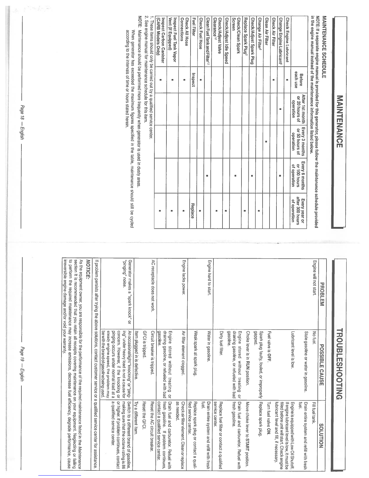
MAINTENANCE
I
MAINTENANCE
SCHEDULE
NOTE:
If
a
separate
engine
manual
is
provided
for
this
generator,
please
follow
the
maintenance schedule
provided
in
the engine
manual
instead
of
the
maintenance
information
listed
below.
B
f
After
1st month
Every
3
months
Every
6
months
Every
year
or
e
ore
or
20
hours
of
or
50
hours
of
or
100
hours after
300
hours
each
use operation
operation
of
operation
of
operation
Check
Engine
Lubricant
Change
Engine
Lubricant2
Check
Air
Filter
Clean
Air
Filter
Change
Air
Filter2
Check/Adjust
Spark
Plug
Replace Spark
Plug2
C
heck/Clean
Spark
Screen
Check/Adjust
Idle
Speed
Check/Adjust
Valve
Clearance2
Clean FuelTank
and
Filter’2
Check
Fuel
Hose
Fuel
Filter
Inspect
Replace
Check
All
Hose
Connections
Inspect
Fuel Tank
Vapor
Vent
(If
Equipped)
Inspect
Carbon
Canister
(CAR
B
Models
Only)
1
These
items should
only
be carried
out
by
a
qualified
service
center.
2.
See
engine
manual
for
maintenance schedule
for
this
item.
NOTE:
Maintenance
should be
performed
more
frequently
when
generator
is
used
in
dusty
areas.
When
generator
has
exceeded
the
maximum figures
specified
in
the
table,
maintenance
should
still
be
cycled
according
to
the
intervals
of
time
or
hours
stated
herein.
TROUBLESHOOTING
PROBLEM
POSSIBLE
CAUSE
SOLUTION
Engine
will
not
start.
No
fuel.
Fill
fuel
tank.
Stale gasoline
or
water
in
gasoline.
Drain
entire
system
and
refill
with
fresh
fuel.
Lubricant
level
is
low.
EngineisequippedwithLowOilShutoff.
If
engine
lubricant
level
is
low,
it
must
be
filled
before
unit
will
start.
Check
engine
lubricant
level
and
till,
if
necessary.
Fuel
valve
is
OFF.
Turn
fuel
valve
ON.
Spark
plug
faulty,
fouled,
or
improperly
Replace spark
plug.
gapped.
Choke
lever
is
in
RUN
position.
Move
choke
lever
to
START
position.
Engine
stored
without
treating
or
Drain fuel
and carburetor.
Refuel
with
draining
gasoline,
or
refueled
with
bad
fresh
gasoline.
gasoline.
Dirty
fuel
filter.
Replace
fuel
filter
or
contact
a
qualified
service center.
Engine hard to
start.
Water
in
gasoline.
Drain
entire
system
and
refill
with
fresh
fuel.
Weak
spark
at
spark
plug.
Replace spark
plug
or
contact
a
quali
fied
service center.
Engine
lacks
power.
Air
filter
element clogged.
Check airfilterelement.
Clean
or
replace
as
needed.
Engine
stored
without
treating
or
Drain
fuel
and
carburetor.
Refuel
with
draining
gasoline,
or
refueled
with
bad
fresh
gasoline.
It
problem
continues,
gasoline,
contact
a
qualified
service
center.
AC
receptacle does
not
work.
Circuit
breaker
is
tripped.
Reset the
AC
circuit
breaker.
GFCI
is
tripped.
Reset
the
GFCI.
Item
plugged
in
is
defective.
Try
a
different
item.
Generator makes
a
spark
knock”
or
An
occasional
light
“knocking”
or
“ping- Switch
to
a
different
brand
ot
gasoline,
“pinging”
noise.
ing”
under
heavy
load
is
not
a
cause
tor
making
sure
that
the
octane
rating
is
86
concern.
However,
if
the
knocking
or or
higher,
If
problem
continues,
contact
pinging
occurs
under
normal
load
at
aa
qualified
service
center.
steady
engine
speed,
the
problem
may
bewiththe
brand
of
gasoline
being
used.
If
problem
persists
after
trying
the
above
solutions,
contact
customer
service
or
a
qualified
service
center
for
assistance.
NOTICE:
As
the
equipment
owner, you
are
responsible
for
the
performance
of
the
required
maintenance
listed
in
the
Maintenance
section
It
is
recommended
that
you
retain
all
receipts
covering
maintenance
on
your
equipment.
Neglecting
or
failing
to
perform
the
required
maintenance
may
increase emissions,
decrease
fuel
efficiency,
degrade
performance,
cause
irreversible
engine
damage
and/or
void
your warranty.
Page
18
—
English
Page
19
—English

WARRANTY
I
LIMITED
WARRANTY
WARRANTY
COVERAGE
OWT
Industries,
Inc.,
(the
Company)
warrants
to
the
original
retail
purchaser
that
this
Black
Max
Product
is
free
from
detects
in
material
and
workmanship
and
agrees
to
repair
or
replace,
at
the
Company’s
sole discretion,
any
defective
Product
free
ot
charge
within
these
time
periods
trom
the
date
of
purchase:
•
Two
years,
if
the
Product
is
used
solely
tor
personal,
family,
or
household
use;
•
One
year,
it
the
Product
is
used
for
business
or
commercial use.
This
warranty
applies
only
to
Products
sold
within
the
United
States
of
America,
the
District
ot
Columbia,
Canada,
Mexico,
the
Commonwealth
of
Puerto
Rico,
the
Virgin
Islands, Guam,
the
Canal
Zone,
or
American
Samoa.
This
warranty
is
not
transferable and
does
not cover
damage
resulting
trom
defects
other than
in
material
or
workman
ship,
or
damage
caused
by
unreasonable
use,
including
the
failure
to provide
reasonable
and
necessary
maintenance.
Other items
not
covered
under
this
warranty
include:
•
Transportation
charges
tor
sending the
product
to
the Company
or
its
authorized service
representative
for
warranty
service,
or
for
shipping
repaired
or
replacement
products
back
to
the
customer;
these
charges
must
be
borne
by
the
original
retail
purchaser.
•
Engine.
Your
Product
is
equipped
with
an
engine
that
is
covered
exclusively
by
a
separate
warranty
from
the
engine
manufacturer.
Please
refer to
the
engine manual included
with
the Product
for
warranty
information
related
to
the
engine.
•
Damages
caused
by
abuse,
accident,
misuse,
neglect,
alteration, modification,
the effects
of
corrosion,
erosion,
normal
wear
and
tear
or
repairs
by
other than the
Company
or
its
authorized
service
representative.
Warranty
is
voided
if
the
customer
fails
to install,
maintain
and
operate
the
product
in
accordance
with
the
instruc
tions
and
recommendations
ot
the
Company
as
set
forth
in
the
Product’s
operator’s
manual
or
if
the
Product
is
used
as
rental
equipment.
The
Company
will
not pay
for
repairs
or
adjustments
to
the Product,
or
for
any
costs
or
labor,
performed
without
the
Company’s
prior
authorization.
IMPORTANT:
Some
components
not
covered under this
warranty
may
still
be
covered
by
a
separate
warranty
issued
by
the
engine manufacturer.
Please
see
the
Engine
Manufacturer
Warranty
(if
any)
supplied
with
this
product
for
further details.
SAVE
YOUR
SALES
SLIP
Proof
of
purchase
in
the
form
of
your
dated
sales
receipt,
cash
register
slip,
etc.
showing
the
serial
number
and
the
model
of
your
Product
will
be
required before
the
Company
and/or
its
authorized service
representatives
can
perform
warranty
service
on
the Product.
EXCLUSIONS
AND
LIMITATIONS
THIS
LIMITED
WARRANTY
IS
IN
LIEU
OF
ALL
OTHER
EXPRESS
WARRANTIES.
ANY
IMPLIED
WARRANTY
OF
MERCHANTABILITY,
FITNESS
FOR
A
PARTICULAR
PURPOSE,
OR
OTHERWISE,
APPLICABLE
TO
THIS
PRODUCT,
SHALL
BE
LIMITED
IN
DURATION
TO THE
DURATION
OF
THIS
LIMITED
WARRANTY.
THE
WARRANTY
SERVICE
DESCRIBED
ABOVE
IS
THE
EXCLUSIVE REMEDY
UNDER
THIS
WARRANTY.
THE
COMPANY
SHALL NOT
BE
LIABILE
FOR
ANY
SPECIAL,
INCIDENTAL
OR
CONSEOUENTIAL
DAMAGES.
SOME
STATES
DO
NOT
ALLOW
A
LIMITATION
ON
THE
DURATION
OF
IMPLIED
WARRANTIES,
OR THE EXCLUSION
OR
LIMITATION
OF
INCIDENTAL,
OR
CONSEOUENTIAL
DAMAGES,
SO
THE
ABOVE
LIMITATION
OR
EXCLUSION
MAY
NOT APPLY TO
YOU.
HOW TO
OBTAIN
WARRANTY
SERVICE
For
warranty
service:
Call
toll
free
1-800-726-5760, or
write
to
OWT
Industries,
Inc.,
RO.
Box
35,
Highway
8,
Pickens,
SC
29671.
For
warranty service
outside the
USA,
please
contact
your local Black
Max
dealer.
WARRANTY
LIMITED
ENGINE
WARRANTY
OUCAR
Corporation
will
repair
or
replace,
free
of
charge,
any
whet
appears
to
be premeture
wear.
Such
wear,
when
caused
part(s(
of
the engine
that
is
detective
in
materiel
or
workmanship
by
dirt,
duet,
spark
plug
cleaning
grit,
or
other
abrasive
materiel
or
both.
Transportation
charges
on
product submitted
for
repair
that
has entered
the
engine
because
of
improper
maintenance,
or
replacement
under
this
warranty
must be
borne
by
purchaser.
is
not
covered
by
warranty.
This
warranty
is
effective
tor
and
is
subiectto
the
time
periods
and
This
warranty
covers
engine
related
defective material
and!
conditions
stated
below.
For
warrsnty service,
find
the
nearest
or
workmanship
only,
and
not
replacement
or
refund
of
the
Authonzed Service
Dealer
in
our
dealer
locator map
at
DUCAR.
equipment
to
which
the
engine
may be
mounted.
Nor
does
There
is
no
other
expressed
warranty.
Implied
warranties,
the
warranty
extend
to
repairs
required
because
of:
including
those
of
merchantability
and
fitness
fora
particular
1.
Problems
caused
by
parts that
are
not
original
DUCAR.
purpose,
are
limited
to
two
years
from
purchase,
or
to
the
2.
Equipment
controls
or
installations
that
prevent starting,
extent
permitted
by
law
end
all
imptied
warranties
sre
ex
cause
unsatisfactory
engine
performance,
or
shorten
engine
cluded.
The
warranty
period
begins
on
the date
of
purchase
life.
(Contact
equipment
msnufacturer.(
by
the
first
retait
consumer
or
commercial end
user.
Liability
for
incidentat
or
consequential
damages
are
excluded
to
the
Leaking
carburetors,
clogged
fuel
pipes,
sticking
valves,
or
extent
exclusion
is
permitted
bylaw.
Some
atates
or
countries
other
damage, caused
by
using
contaminated
or
stale
fuel.
donotallomlimitationaonhomlonganimpliedwarrentyleata,and
4.
Parts
which are
scored
or
broke
because
an
engine
wan
some
states
or
countries
do
not
allow
the
ssclusion
or
limitation
operated
with
insufficient
or
contaminated
lubricating
oil,
or
ot incidental
or
consequential
damages,
so
the
above
limitation
an
incorrsct
grade
of
lubricating
oil
tchsck
and
refill
when
end exclusion
may not
apply
to
you.
This
warranty
gives
you
necessary,
and
change
at
recommended
intervals).
OIL
specific
legal
rights
and
you
may
also
have
other nghts
which
CARD
may
not
shut
down
running
engine.
Engine
damage
vary
from
state
to
state
end country
to
country. may
occur
it
oil
level
is
not
properly
maintained.
No
warranty registration
is
necessary
to
obtain
warranty
on
5.
Repair
or
ndIustment
of
associated
parts
or
sssemblies
such
OUCAR.
Save
your
proot
of
purchase
receipt.
If
you
do
not
as
clutches, transmissions,
remote
controls, etc.,
which
are
provide
proof
of
the
initial
purchase date
at
the
time
warranty
not
manufactured
by
DUCAR.
service
is
requested,
the
manufacturing
date
of
the
product
5.
Oamege
or
wear
to
parts
caused
by
dirt,
which
entered
wilt
be
used
to
determine the warranty
period,
the
engine
because
of
improper
air
cleaner
maintenance,
ABOUT YOUR
WARRANTY
rs-assembly,
or
use
of
a
non-original
sir
cleaner element
or
cartridge.
At
recommended
intervals,
clean
and/or
replace
OUCAR
welcomes
warranty
repair
and
apologizes
to you
for
be-
the
titer
as
staled
in
the Operator’s
Msnuel.
ing
inconvenienced.
Any
Authorized
Ssrvics
Dealer
may
perform
marrenly repairs.
Mont
warranty repairs
are
handled
routinely,
but
7.
Parts
damaged
by
over-speeding,
or
overheating
caused
sometimes
requesteforwarranty
servicemay
not
be
appropriate.
by
grass,
debris,
or
dirt,
which
plugs
or
clogs
the
cooling
fins,
or
flywheel
area,
or
damage
caused
by
operating
the
It
a
customer
differs
with
the decision
ot
the
Service
Dealer,
an
engine
ins
contned
ares
without
sufficient ventilation.
Clean
investigation
will
be
made
to
determine
whether
the
werenty
engine
debris
at
recommended
intervals
as
staled
in
the
applies.
Ask
the Service
Dealer
to
submit
all
supporting
tscts
Operator’s
Manuel.
to
his
Distributor or
the
Factory
for review.
It
the
Distributor
or
the
Factory
decides
that
the
claim
is
Iustified,
the
customer
will
Engine
or
equipment
parts
broken
by
esceusive
vibration
be
tully
reimbursed
for
those
items
that
are
detective.
To
avoid
caused
by
a
loose
engine
mounting,
loose
cutter blades,
misundvrstaedingwhichmightoccurbetweenthecustomersnd
unbalanced blades
or
loose
or
unbalanced
impellers,
the
Dealer,
listed below
are
some
of
the
causes
of
engine
failure
improper
attachment
of
equipment
to
engine
crenknheft,
that
the
merranty
does
not
cover,
over-speeding
or
other
abuse
in
operation.
Normalwear:Engines.likeellmechsnicaldevices,needperiodic
g.
A
bent
or
broken
crankshaft,
caused
by
striking
a
solid
parts service
and
replacement
to
perform
well.
Warranty
will
not
obiect
with
the cutter
blade
ot
e
rotary
lawn
mower,
or
cover
repair when
normal
use
hee
esheusted
the
its
of
a
part
or
escesuive
v-belt
tightness.
an
engine.
Warranty would
not epply
if
engine
damage
occurred
10.
Routine
tune-up
or
adlustment
of
the engine.
because
ot
misuse,
lack
of
routine
maintenance,
shipping,
hen-
11.
Engine
or
engine
component
failure,
i.e.,
combustion
chem
dung,
warehousing
or
improper
installation.
Similarly
warranty
is ber,
valves,
valve
seats,
valve
guides,
or
burned
starter
void
if
the
serial
number
of
the engine
has
been
removed
or
the
motor
windingu,
caused
by
the
use
of
alternate
fuels
such
engine
has been
altered
or
modified, as,
liquefied
petroleum,
natural
gas,
altered
gasoline,
etc.
Improper
maintenance:
The
tite
of
an
engine
depends
upon
IF
YOU
HAVE ANY
OUESTIONS
REGARDING YOUR
WAR
thy
conditions under
which
it
operates,
and the
cere
it
receives.
RANTY
RIGHTS
AND
RESPONSIBILITIES,
CONTACT
OWT
Some
epplicetionu,
such
as
tillers,
pumps
and
rotary
mowers,
INDUSTRIES,
INC.,
at
1-800-726-5760.
are
very
often
used
in
dusty
or
dirty
conditions,
which
can
cause
Page
21
—
English
Page
20
—
English
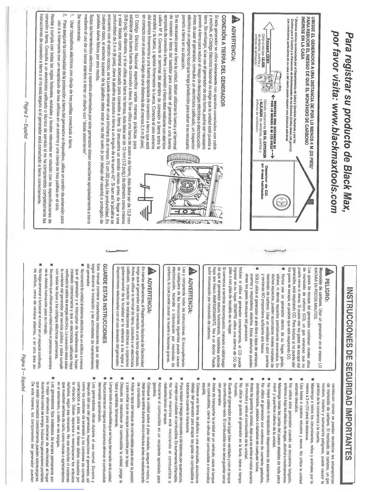
GUARDE ESTAS
INSTRUCCIONES
Este manual
contiene importantes instrucciones qua
se
deben
seguir
durante
Ia
instalación
y
las
actividades
de
mantenimiento
del
gonerador.
I
No
conecte
Ia
unidad
al
sistema
eldctrico
do
an edit
1cm
a
menos
que
el
generador
y
el
interruptor
do
transferencia
ae
hayan
instalado
correctamente
y
qua
un
electricista
calificado haya
venticado
Ia
salida
do
energia
eléctrica.
La
conexiOn
debe
aistar
Ia
corrionte
del
generador
del
aervicio
püblico
y
debe
cumplir
con
todas
as
leyes
y
los
códigos eléctricos pertinentes.
•
No
pennita
quo
utilicen
esta
urodad ninos
ni
personas
carentes
do
Ia
debida
instruccidn
para
su
manejo.
•
No
haga arrancar
o
funcionar
el
motor
en
un
espacio
confinado,
do
edificio,
cerca
do
ventana abiertas,
o
en
otto
area
sin
vontilaciön
donde se
puedan
recoloctar
as emanaciones
de
monöxido
de
carbono.
El
monOsido
de
carbono,
un
gas
incoloro,
inodoro
y
sumamente
peligroso,
puede
causar
a
përdida
de
Ia
conciencia
o
a
muerte.
•
Mantenga
a
todos
los
circunstantes,
nidos
y
animates
pot
lo
menos
a
3m
(10
pies)
de distancia.
•
Use
botas
0
zapatos
robustos
y
secos.
No
ut/ice
Ia
unidad
estando
descalzo.
•
No
utilice
oste
generador
cuando se encuentre
fatigado,
enfermo
o
bajo
los
efectos
do
drogas,
alcohol
o
medicamentos.
•
Mantenga
todas
las
partes
del
cuerpo
aleiadas
de
toda
pieza
mdvil
y
superticie
caliente
do
Ia
unidad.
•
No
toque
cables
ni
recoptãculos desprovistos
do
sislamiento.
•
No
utilice
el
generador
con
cordones
do
cornente
gastados,
deshilachados,
pelados
0
danados
do cualquior torma.
I
Antes do
quardar
Ia
unidsd,
dole
quo
so enfrio
el
motor
durante
30
minutos
y
retire
ol
combustible
do
Ia
unidad.
•
No
utilico
or
guardo
el
gonorador
en
Ia
Iluvia,
nieve
o
tiempo
hümedo.
•
Guarde
el
generador
on
us luger
bion
vontilado
y
con
el
tanque
do
combustible
vaclo
El
combustible
no
so
debo
guardar
corca
dot
generador.
I
Anton
do
transportar
Ia
unidad
on un
vehiculo,
VaClO
01
tanquo
do
combustible,
ciorro
Ia
välvula
del
combustible
e
inmovilico
aquëlla.
•
Coloque
usa
Iámina
do
plãstico
o
una
almohadilla
absorbente
dobajo
dot
generador
para
atrapar
as gotas
de combustible
a
lubricanto
cuando
to
transporto.
•
Para
roducir
ol
riosgo
de
incondio
o
do
losiones
por
quemadura,
manelo con
cuidado
ol
combustible.
Es
sumamente
inftamable.
•
No
fume
mientras estd mezctando
el
combustible
o
roabasteciendo
ol
tanque.
•
Almacone
el
combustible
en
an
rocipiento
aprobado
para
gasolina.
•
Coloque
Ia
unidad
sabre
01
I50
nivelado,
apague
el
motor,
y
deje quo so
enfrie
durante
cinco minutos
antes
do
reabastecerla
do
combustible.
•
Aflole
Ia
taps
del
tanque
do
combustible
para
altviar
Ia
prosidn
y
para
evilar
quo so
escape
combustible
pot
Is
tapa.
•
Después
do
reabastecer
do
combustiblo
Ia
unidad
ponga
Ia
tapa
y
apriétela
firmemente.
•
Limpie
todo
el
combustible
quo
so
haya
derramado
do
Ia
unidad.
•
Nunca intente
en
ninguna
circunstancia
eliminar
ol
combustible
dorramado
quecnandolo.
•
Los
gonoradores
vibran
durante
el
uso
normal.
Duranto
y
dospués
del
uso
del
generador,
inspocciono
el
genorador, sal
como
los
cordonos
do
extensiOn
y
los
cordones
do
corriente
conectados
a
ësto,
pars
vet
si
tionon
danos
causados
por
Ia
vibraciön.
Doben
ropararso
o
roemplazarse
los
articulos
daOados,
segOn
sea
necosario.
No
use
enchutos
ni
cordones
quo
muostren
senates
do
daho,
como
roturas
o
agrietamientos
en
el
aislamiento,
0
daño
en
las
ospigas.
I
Los
generadores
fijos
instalados
do
manors pormanento son
a
mejor
alternativa para
abastecer
do
electricidad
al
hogat
durante
los
cortos
do
energia.
Incluso
los
generadoros
portables
quo
estdn
coneclados
correctamente
pu000n
sobrecargarse.
Do
esta
manora,
los
componentes
dot
generador
pueden
Para
registrar
su
producto
de
Black
Max,
por
favor
visita:
www.blackmaxtools0corn
UBIQUE
EL
GENERADOR
A
UNA
DISTANCIA
DE
POR
LO
MENOS
6
M
(20
PIES)°
PARA
REDUCIR
EL
RIESGO
DE
QUE
EL
MONOXIDO
DE
CARBONO
INGRESE
EN
LA
CASA
INSTRUCCIONES
DE
SEGURIDAD
IMPORTANTES
•
Distaocia
minima
recnmaodada
par
&
Depaflamonto
do
Saludy
Sowicius Humanus
y
par
los
Contns
pam
a?
Contmly
Ia
Pmvoncido
do
Entennedados
do
los
Estados
Unidos
(www.cdc.go
v/ca).
Las
condiciones
pafliculams
do
so
casa
a
do?
viento
puede
mqu
oAr
una
dislancia
adiciona?.
MANT100
IINA
UISTANCIO
DI
____________________
,
4PDN
LU
MINDS
GM
(20
PIESI’*
Ee,pc
(COt
,
.L;
Utilicolo
tinicamente
EN
EL
EXTERIOR
Dwis
I
escape
1.0105
/
ALE1000
do
ventanas,
puertes
do
veotanas.
puertas
v
‘.,
l
onficios
do
ventilaciOs.
scrfoiss
do
vent/aeOn
Ooteotmr
d
CO
en
âmes
habitedas
3
A
Monóxido
de
carbono.
Usar
un
generador
on
el
interior
LO
MATARA
EN
POCOS
MINUTOS.
Los
gases
do
escape
del
generador
contionen
nivoles
altos
do monOxido
do
carbono
(CO),
un
gas
venenoso
quo
no
puede
verse
ni
olerse.
Si
puede
oter
los
gases
do
escape
del
goneradot,
está
reapirando
CO.
Pets
incluso
si
no
puede
oler
los
gases
do
escape,
es
posiblo quo
osté
respirando
CO.
I
Nunca
use
un
gonerador dentro
do
su
hogar,
garaje,
sötano,
ni
demOs
espacios
parciatmente
encorrados.
En
dichos
ospacios, pueden
acumularse
niveles
mortales
do
monOeido do
carbono.
Ussr
un
ventilador
o
abrir
puertas
y
ventanas
NO
proporciona
suficiente
sire
fresco
•
SOLO utitice
el
gonerador
at
sire
libre
y
bios
do
ventanas,
puertas
y
respiraderos
abiortos.
Estas aborturas
pueden
atraer
los
gases
do
escape
del
genorador.
Incluso
si
utiliza
el
generador
corroctamente,
el
CO
puede
ingressr
en
su
hogar.
SIEMPRE
utilice
usa
alarma
do
CO
de
pilas
o
con
pilas do
respaldo
on
su
hogar.
Si
comienza
a
sentirso
descompuesto,
mareado
0
débll
luogo
do
quo
ol
gonerador
estuvo funcionando,
traslOdese
adonde
hays
aire
fresco
INMEDIATAMENTE.
Vea
a
an
doctor.
Puede
sutrir intoxicaciOn
por
monOxido do
carbons.
A
CONEXION
A
TIERRA
DEL
GENERADOR
Si
este genetador
so
utilizs
ünicamente
con
aparatos
conectsdos
con
cable
y
enchufe,
eI
COdigo
Eléctrico Nacional
no
exige
quo
Ia
unidad
esté puesta
a
tierra.
Sin
embargo,
si
so
usa
el
generador
do
otra
forms, podria
sot necesarlo
ponorlo
a
tierra
para
reducir
el
riesgo
do
descargas
etectricas
0
electrocuciOn.
Antes
do
usar
el
generador,
consulte
a
un
electricista
calificado,
un
inspector
elëctrico
o
un
organismo
local
que
tenga
jurisdicción
pars
saber
si
es
necesario
ponerlo
a
tierra en
su
situaciOn.
Si
os
necosatio poner
a
tierra
Is
unidad,
deben
utilizarse
Ia
tuorca
y
el
terminal
do
conexion
atierra del
bastidor
pars
conectar
el
generador
a
una
fuente
apropiada
do conoxiOn
a
tiorrs.
La
conexiöna
tierrs
dobe
reslizatse
con
alambre
calibre
N° 5.
Conecte
el
terminal
del
alambre de
conoxiOn
a
tierra
entro
Is
arandels
y
atuerca,
y
apriete
firmemonte
Ia
tuorca.
Conocte
el
otto
oxtromo
del
alambre
firmernente
a
una
fuente
apropiada de
conexiön
a
tierra
que
esté
en
contacto
COfl
el
suolo
sb
argo
do
una
distancia
deal
monos
2,4
m
(B
pies).
El
Codigo
Eléctrico Nacional
especifica
variss
manoras práctlcas
para
establecer
una
buena
fuonte
do
conexjón
a
tierra.
Si
se
utiliza
una barra
do
acero
o
de
hierro,
ésto
debe
ser
do
15,9
mm
(5/8 pulg.)
do diárnetro,
y
si
so
utiliza
una
barra
no
fetrosa,
ësta
debe
ser
do
13mm
(1/2
pulg.)
de
diãrnotro
corns
minimo
y
estar
listada
corno
material
adecuado
para
conexión
a
tierra.
Si
encuentra
un
estrato
rocoso
antes
de
Ilegar a
una
ptofundldad
de
2,4
m
(8
pies),
dave
Is
abalina
do
puesta
a
tierra
a
us
angulo
de
a
Is
sumo
45.
Si
aun
asils
abatina
se
oncuentra
con
el
estrato
rocoso,
so
Ia
puode
enterrar
on
una
trinchera
do
al
menos
75
cm
(30
pulg.)
de profundidad.
En
cualquior
caso,
el
extremo
superior
do
Is
jabslina
debe estar
sI
ras
del
suebo
)o
por
debsjo
del
rasante)
aprotegido
do
posibles
danos
fisicos
pot
otto
medio.
Todas
las
herramientas eléctricas
y
aparatos
alimentadoa
pot
este generador
deben
conoctarse
apropiadamento
a
tierra
mediante
el
uso
do
un
tercet
alambre
otoner
un
diseno con
“doble
sislamiento”.
Se recomienda;
1.
Usar
dispoaitivos
eléctricos
con
davis
de
tres
patillas
conectads
a
ties’s.
2.
Para
asegurar
Ia
continuidad
do
Is
protoccion
atierra
del
gonorador
al
dispositivo,
utilice
un
cordOn
do
extension
pars
uso
a
Ia
intemperie con
un
recoptacuto
do
tres
orificios
en
un
extremo
y
una
clavija
do
tros
patillas
en
el
Otto.
Gevise
y
cumpla
con
todas
las
reglss
federsbes,
estatales
y
locales
relevantes
en
relaciön
con
las
espociticaciones
do
conexiOn a
tiorra.
Consulte
a
an
ebectricista
calificsdo
o
técnico
do servicio
si
no
ha
comprendido completamento
las
instruccbones do
conexiOn a
tierra
0
si
no
estO
seguro
si
et
generador
estO
conectado
a
ties’s
correctamente.
A
Lea
y
comprenda
todas
las
instrucciones.
El
incumplimiento
de
cuslquiera
de
las
instrucciones
aiguientos
puede
causar
electrocuciOn,
incendlo
a
intoxicaciOn
pot
monOxido do
carbono,
lo
cual
pu000
causar
Is
muerte
0
lesiones
graves.
A
En
ciortas aplicaciones,
el
Regtatnento
Nacionst do
Ebectricidad
exige
quo
el
generador
estO
conectsdo
a
una
tierra
aprobada.
Antes do
utilizar
Ia
terminal
do ties’s,
consulte
a
un
electncista
calificado,
inspector
do
inatalaciones
elOctricas
u
organismo
gubernamental
do
Ia
localidad
en
bo
roferente
a
las
roglas
y
disposiciones
retacionadas
con
ol
Uso
deseado
dot
generador.
Pagina
2—
Espanol Pàgina
3—
Españo!
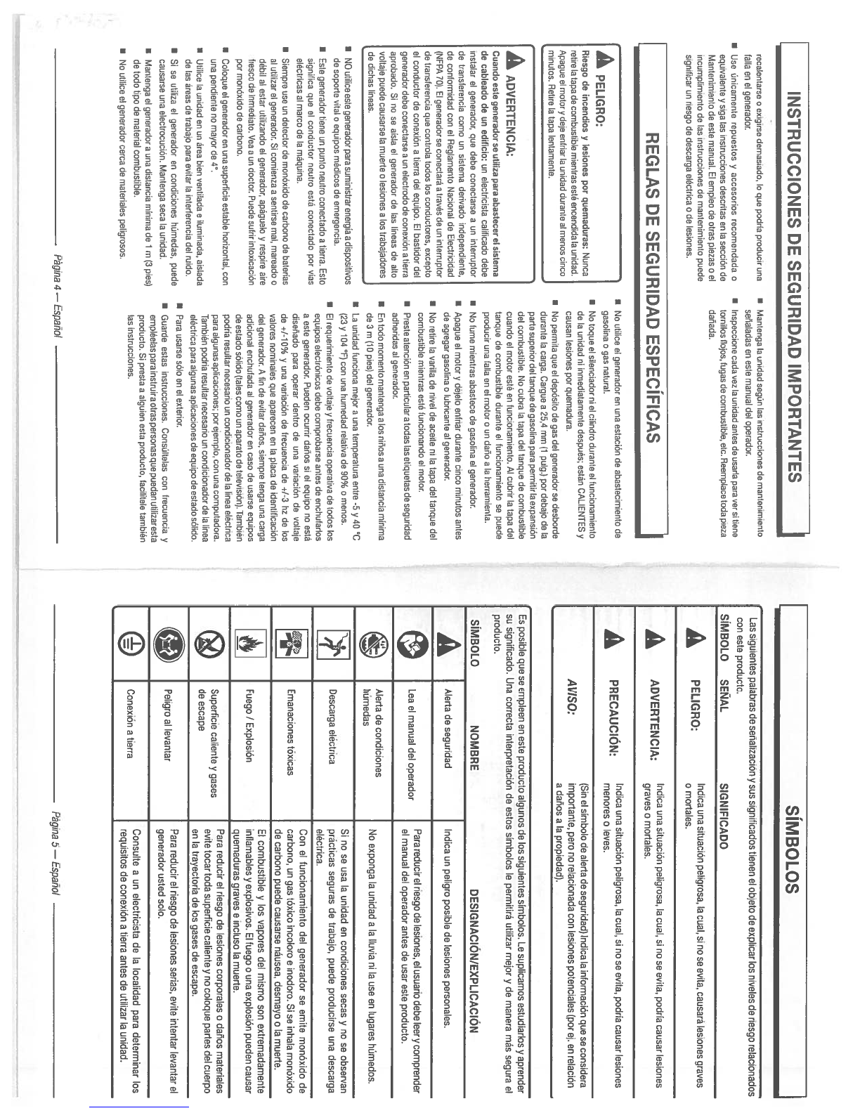
•
NO
utilice
oate
gonorador para
auminiatrar onorgia
a
diapeaitivoa
do
aoporto
vital
a
equipoa médicoa
do
omergoncia.
I
Eato
gonorador
tiono
un
punto
noutro
conoctado
a tiorra. Eato
aignitica quo
ol
conductor
noutro
oatá
conoctado
per
viaa
oldctricaa
al
marco
do
Ia
mdquina.
•
Siompro
uao
un
dotoctor
do
monovido
do
carbono
do
batoriaa
al
utilizar
ot
gonorador.
Si
comionza
a
aontirao
mat,
maroado
o
ddbil
at
oatar
otitizando
ol
gonorador,
apaguolo
y
roapiro
airo
troaco
do
inmodiato.
Voa
a
on
doctor.
Puodo
autrir
intoxicacidn
por
mcnóvido
do
carbono.
•
Cotoqoo
01
gonoradcr
on
una
auporticto
oatablo
horizontal,
con
una pondionto
no
mayor
do
4.
•
Utitico
Ia
onidad
on on
ároa
bion
vontilada
o
iluminada,
aialada
do
ba
droaa
do
trabajo
para
ovitar
Ia
intortoroncia
dol
ruido.
•
Si
00
utiliza
ol
gonorador
on
condicionoa hdmodao,
puodo
cauaarao
una
oboctrccución.
Mantonga
aoca
Ia
unidad.
•
Mantonga
ol
gonorador
a
una
diatancia
minima do
1
m
(3
pioa)
do
todo
tipo
do
matoriat
ccmbuatiblo.
•
No
utilico
ol
gonorador corca
do
matorialoa poligroaoa.
•
Na
utilico
ot
gonorador
on
una oatactón
do
abaatocimionto
do
gaaolina
0
gaa natural.
•
No
toquo
ol
ailonciador
ni
ol
cilindro
duranto
ol
tuncionamionto
do
Ia
unidad
01
inmodiatamonto
doapuéa;
oatán
CALIENTES
y
cauaan
Ioaionoa
por
quomadura.
•
No
pormita quo
ol
dopóaitn
do
gaa
dot
gonorador
ao
doabordo
duranto
Ia
carga.
Oarguo
a
25,4
mm
(1
pulg.(
per
dobajo
do
Ia
patio
auporior
dot
tanquo
do
gaaolina
para
pormitir
Ia
ovpanaiOn
dot
combuatibto.
No
cubra
Ia
tapa
dol
tanquo
do
combuatibto
cuando
ot
motor oaté
on
tuncionamionto.
Al
cubrir
Ia
tapa
dol
tanquo
do
combuatiblo duranto
ol
tuncionamionto
ao
puodo
producir una
talta
on
ot
motor
o
un
daño
a
Ia
horramionta.
•
No
tumo
miontraa
abaatoco
do
gaaolina
ot
gonorador.
•
Apaguo
ot
motor
y
déjolo
ontriar
duranto
cinco
minutes
antoa
do
agrogar
gaaotina
a
lubricanto
at
gonorador.
•
No
rotiro
Ia
varilta
do
nivot
do
acoito
ni
Ia
tapa
dol
tanquo
dol
cembuatibla
miontraa
oaté
funcbonando
ol
motor.
•
Proato
atanción
on
particular
a
tedaa
lao
otiquotaa
do
aoguridad
adhoridaa
al
gonurador.
•
En
todo
momonto
mantonga
alea
niñoa
a
una
diatancia
minima
do
3m
(10 pioa(
dol
gonoradoc
•
La
unidad tunciona
mo(or
a
una
tomporatura
ontro
-5
y
40
C
(23
y
104
F)
con una
humodad
rolativa
do 90%
a
monoa.
•
El
roquorimionte
do
vottajo
y
trocuoncia oporativa
do
todoa
tea
oquipoa
oloctrónicoa
dobo cnmprobaroo
antoa
do
onchutarino
a
oato
gonorador.
Puodon
ocurrir
dahoo
oi
ol
oquipo
no
oatd
diaonado
para
oporar
dontro
do
una variación
do
voltajo
do
+1-10%
y
una variaciôn
do
trocuoncia
do
+1-3
hz
do
lea
valoroa
nominaloo quo
aparocon
on
Ia
placa
do
idontiticaciOn
dol
gonorador.
A
tin
do ovitar
danoa,
oiompro
tonga
una
cargo
adicional
anchutada
al
gonorador
on
caao
do
uaaraa
aquipea
do
ostado
odlide
(talon
come
on
aparato
do
toleviaion(.
TambiAn
podria
rooultar
nocoaario
un
condicionador
do
Ia
linoa
oléctrica
para
algunan aplicacionoa; poro(omplo, con
000
computadera.
También
podria
rosultar
nocosario
on
condicienador
do
Ia
boa
oléctrica
para
algunaa
aplicacienon
do
oquipe
do
ontado
oólide.
•
Para
unarne
adlo
on
ol
oxtorior.
•
Guardo
ontao
inatruccionoa.
ConaUltolaa
con
trocuoncia
y
ompléobao
para
inotruira
etraa
porsonaa
quo
puodan
utilizaroota
producta.
Si
proota
a alguion
oata
producta,
tacilitobo
tamblén
lao
inotruccionos.
INSTRUCCIONES
DE
SEGURIDAD
IMPORTANTES
rocalentarno
a
oxigiroo
demaniado,
Ia
quo podria
preducir
una
I
Mantonga
Ia
unidad
aegdn
lao
inatruccienos
do
mantenimionto
talla
on
01
gonorador.
sonaladaa
on
osto manual
dol
eperader.
•
Uao
énicamonto
ropuentos
y
accooeriea
rocemondada
a
I
Inapoccienocadavozlaunidadantoadouaarlaparavorsitiono
oquivalonto
y
aiga
Ian
inatruccienon
doncritas
on
to
aoccidn
do
ternillon
tbejen,
tugan
do
combuatiblo,
otc.
Roomplaco
toda
pioza
Mantonimionta
do
osto
manual.
El
omplea
do
otras
piozas
a
ol
dañada.
incumplimionte
do
lao
inotruccionon
do
mantonimionto puodo
oigniticar
on
riosgo
do
doacarga
oléctrica
ado
loaianea.
REG
LAS DE
SEGURIDAD
ESPECIFICAS
I
SIMBOLOS
I
A
Riongo
do
incondios
y
Iostanoa
par
quomaduran:
Nunca
rotiro
Ia
tapa
do
cembuatiblo
miontran ooté
oncondida
Ia
unidad.
Apaguo
ol
motor
y
do(o
ontriar
Ia
unidad
duranto
al
monea
cinca
minutoa.
Rotiro
Ia
tapa
lontamonto.
Las
siguiontos
patabras
do
senalizacibn
y
sos
s(gniflcados
tionen
ol
abjoto
do
explicar
los
nivetos
do
riasgo
rolacionadas
can asto
praducto.
SIMBOLO
SEIAL
SIGNIFICADO
A
PELIGRO:
Indicaunasituación
potigresa,
Ia
cual,
s(
no
so
evita,
causará
losionos
graves
A
ADVERTENCIA:
paligresa,
Ia
cual,
si
no
so
evita,
pedria
causar
A
PRECAUCION:
r:::
poligrasa,
Ia
cual,
si
no
so
ovita,
padria
causar
(SinaI
simbole
do
alerta
do
seguridad(
Indica
Ia
infermaciOn
quo
so
considora
AVISO:
impertanto, pore
na
relacienada
con
lesienes
petonc(alos
(per
ej.
on
ralac(On
a
danos
a
Ia
prepiodad(.
A
Cuanda
aato
gonoradar
sO
otiliza
pare
abastocor
ol
sistoma
do
cabtoada
do on
oditicta:
un
oloctriciata
caliticado
dobo
inatatar
ol
ganerador,
quo
dobo
cenectarso
a
un
intorrupter
do
transtoroncia
coma
un
aiatoma
dorivade
indopondionto,
do
contermidad
con
ol
Roglamonte Nacienal
do
Eloctricidad
(NFPA
701.
El
gonorader
00
conoctard
a
través
do
un
intorrupter
do
tranatoroncia
quo
cantrola
tadea
lea
cendoctaron,
oxcopta
ol
conductor
do
conoaión
atiarra
dol
oquipo.
El
bantider
dot
gonorader
debo
cenoctarso
a
an
oboctrade do
ceneaión
a
tiorra
sprebade.
Si
no
so
aisla
el
gonorader
do
Ian
Iinaan do
alto
voltajo
poedo
causarno
Ia
muorto
a
losianas
a lea
trabajaderos
do
dichaa
linoan.
SIMBOLO
NOMBRE
Es
posiblo
qua
so
empleen
en
esta
producto algunos
do
los
siguiontos
simbolas.
La
suplicamos
astudiarlos
y
aprandor
so sign
ificade.
Una
corrocta
intorpretaciOn do
ostos
simbolos
lo
parmitiré
utilizar
major
y
do
manera
mao
sagura
ol
producta.
DESIGNACION/EXPLICACION
A
Alerta
do
soguridad
Indica
on
peligro
posiblo
do
lesinnes
O
Para
reducir
ol
rbesgo
de
bosinnas,
al
usuarlo dobo
loory
cemprendar
Lea
el
manual
del
oporador
el
manual
del
eperader
antos
do
usar aata
preducte.
“
Alerta
do
condicionas .
‘t-
.
No
oxponga
Ia
unidad
a
(alluvia
ni Ia
use
on
lugaras
humodes.
.
uma
as
•
Sb
no
so
usa
Ia
unidad
en
candic(anos
aecas
y
no
so
ebsorvan
Oescarga
eléctrica
prácticas soguras
do
trabajo,
puede
preducirse
una
doscarga
oléctrica.
Con
01
tuncionamionte
dot
gonorader
so
emite
menóxide
do
Emanaciones tóxicas
carbano,
on
gas
tôxice incelara
o
inedare.
Si
so inhala
monoxide
do
carbano
puode
causarse
nOoses,
dosmaya
a
Ia
muarto.
El
combustIble
y
los
vaperos
del
mbsmo
son
oxtremadamente
Fuogo
/
ExplosiOn
intlamables
y
explosives.
El
fuage
o
una
explosiOn
puedon
causar
—
quomaduras
gravas
a
incluso
Ia
muerto.
®
.
.
Para raducir
el
riesga
do
losianos
cerperales
o
dsnas
matorialos
Suporticia
calionto
y
gases
ovito
tacar
toda
suparficie
cahonte
y
no
coleque patios
del
cuorpo
deoscapo
on
Ia
trayectoria
do
los
gasos
do
escape.
.Para
reducir
ol
riosgo
do
(esionos
serias,
evite
intentar levantar
el
a
Peligre
al
lovantar
genorader
usted sela.
...
Consulto
a on
electric(sta
do
Is
lacalidad
para determinar
(as
Cenasien
a
tiorra
.
—
requisites
do
canexian
a
tierra
antos
do utilizar
Is
unidad.
POgina
4—
Espano(
Pàgina
5—
Espane!
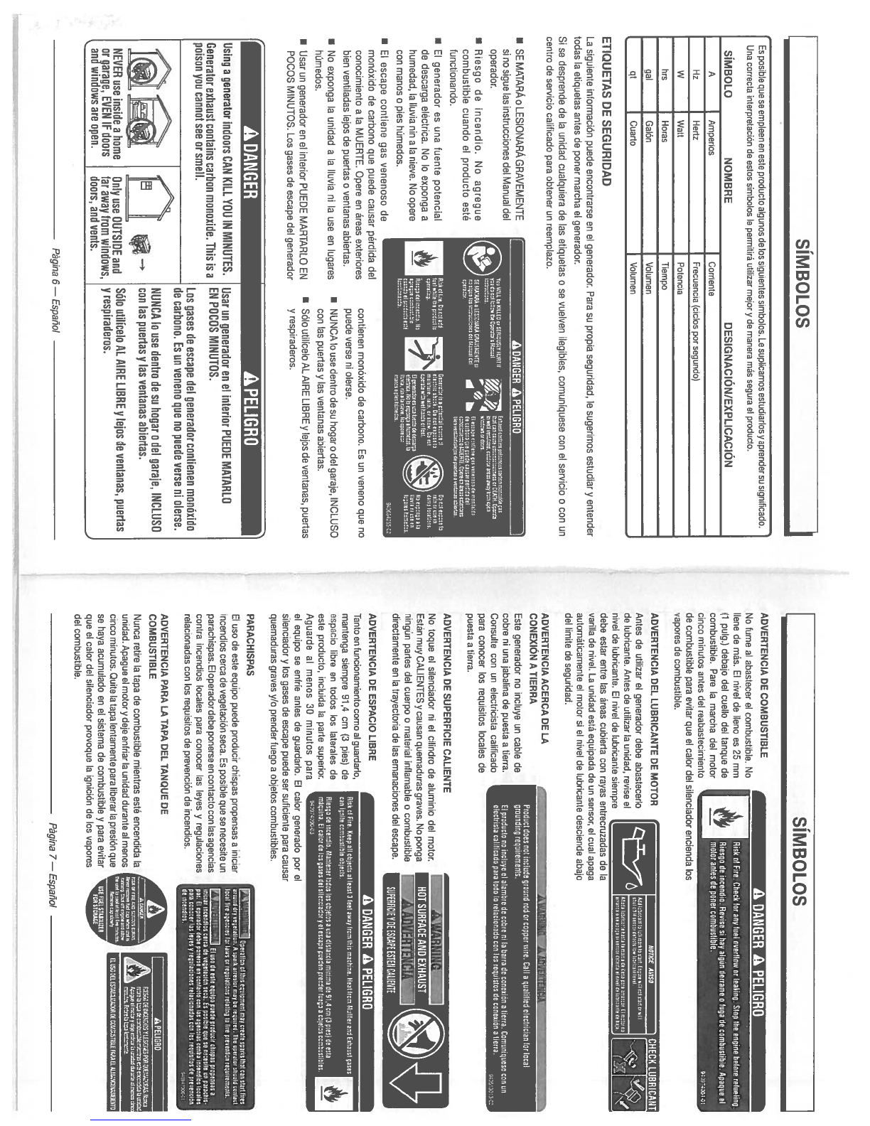
•
SE
MATARA
o
LESIDNARA
GRAVEMENTE
Si
flO
sigue
las
instrucciones
del
Manual
del
operador.
•
Riesgo
de
incendio.
No
agregue
combustible cuando
el
producto
esté
functionando.
•
El
generador
es
una
fuente potencial
de
descarga
eléctrica.
No
In
exponga
a
humedad,
Ia
liuvia
nm
ala
nieve.
No
opete
con
manos
o
pies
hümedos.
•
El
escape
contiene
gas venenoso
de
monOxido
de
carbono que puede
causar
pérdida
del
conocimiento
a
Ia
MUERTE.
Opera
en
areas
exteriores
bien
ventiladas
lejos
de
puertas
o
ventanas
abiertas.
•
No
exponga
Ia
unidad
a
Ia
Iluvia
ni
Ia
use
en
lugares
hémedos.
•
Ussr
un
generador
en
el
interior
PUEDE
MARTARLO
EN
POCOS
MINUTOS.
Los
gases
de
escape
del
generador
ADVERTENCIA
DE
COMBUSTIBLE
No
fume
al
abastecer
el
combustible.
No
Ilene
de
más.
El
nivel
de
Ileno
es
25
mm
(1
pulg.)
debajo
del
cuello
del
tanque
dv
combustible. Pare
Ia
marcha
del
motor
—
cinco minutos
antes
del
reabastecimiento
de
combustible
para
evitar
que
el
calor
del
silenciador
encienda
los
vapores
de
combustible.
ADVERTENCIA
DEL
LUBRICANTE
DE
MOTOR
Antes de
utilizar
el
generador
debe abastecerlo
de
lubricante. Antes
de
utilizar
a
unidad,
revise
el
nivel
de
lubricante.
El
nivel
de
lubricante
siempre
_____________
debe
estsr
entry las
areas
cubierta
con
rayas
entrecruzadas
de
Ia
venus de
nivel.
La
unidad
está
equipada
dv
un
sensor,
el
cusl
apaga
autométicamente
el
motor
si
al
nivel
dv
lubricante
desciende
abajo
del
limite
de
seguridad.
ADVERTENCIA
ACERCA
DE
LA
CONEXION
A
TIERRA
Este
generador
no
incluyv
un
cable
do
cobre
ni
una
jabalina
de
puesta
a
tierra.
Consulte
con
un
electricista
calificado
pars
conocer
los
requisitos locales
dv
puesta
a
tierra.
ADVERTENCIA
DE
SUPERFICIE
CALIENTE
No
toquv
vI
silenciador
ni
el
cilindro
dv
aluminio
del
motor.
Estén
muy
CALIENTES
y
causan quemaduras
graves.
No
ponga
ningén
partes
dvi
cuvrpo
o
material inflamable
o
combustible
dirvctamvnte
en
Ia
trayectoria
dv
las
emanaciones
del
escape.
ADVERTENCIA
DE
ESPACIO
LIBRE
Tanto
en
funcionamivnto
como
al
guardarlo,
mantvnga
siempre
91,4
cm
(3
pies)
dv
vspacio
librv
en
todos
los
laterales
de
vstv producto,
incluida
Ia
party
superior.
Aguarde
al
menos
30
minutos
pars
el
vquipo
se
enfriv
antvs
dv
guardarlo.
El
calor
gvnerado
por
vI
silenciador
y
los
gases
de
escape
puede ser
suficiente
para
causar
quvmaduras
graves
yb
prender
fuego
a
objetos
combustibles.
PARACHISPAS
El
uso
dv
vste
equipo
puvdv
producir
chispas propvnsas
a
iniciar
incendios
cerca
dv
vegvtacián
seca.
Es
posiblv
qua sv
nvcvsitv
un
_____________
parachispas.
El
operadordebe
ponerse
en
contacto
con
las
agendas
contra
incvndios
locales
pars conocer
las
eyes
y
regulacionvs
rvlacionadas
con
los
rvquisitos de
prevencion
dv
incendios.
ADVERTENCIA
PARA
LA
TAPA DEL
TANQUE
DE
COMBUSTIBLE
Nunca
retire
Is
tapa
de
combustible
mientras
esté encendida
Ia
unidad. Apaguv
el
motor
y
deja
enfriar
Ia
unidad
durante
al
menos
dinGo
minutos.
Quite
Ia
taps
lvntamvnte
pars
libvrar
Ia
presion
qua
_______________
se
haya
acumulado
en
el
sistema
dv
combustible
y
pars
evitar
___________
qua
el
calor
del
silenciador
provoquv
Ia
igniciOn
dv
los
vaporvs
del
combustible.
.
SIMBOLOS
SIMBOLO NOMBRE
Es
poaiblv
qua
se
empleen
en
este
producto algunos de
los
siguientes
simbolos.
Le
suplicsmos estudiarlos
y
aprendvr
su
signiticado.
Una
corrvcta
nterpretaciOn
dv
estos
simbolos
lv
permitirá
utilizar
mejor
y
dv
manera
més
segura
el
producto.
DESIGNACION/EXPLICACION
A
Amperios Corriente
Hz
Hertz
Frecuencia
(ciclos
por
segundo(
W
Watt
Potvncia
hrs
Horas Tiempo
gal
Galön
Volumen
qt
Cuarlo
Volumvn
SIMBOLOS
A
DANGER
A
PEUGRO
ETIQUETAS
DE
SEGURIDAD
La
siguivntv
informaciOn
puade
encontrarse
an
el
generador.
Para
su
propia
seguridad,
lv
sugvrimos
estudiar
y
vntender
todas
Ia
etiquetas
antes
dv
poner marcha
vI
generador.
Si
se
desprvnde
dv
Ia
unidad cualquivra
dv
las
etiquetas
o
sv
vuelvvn
ilegibles,
comuniquvse
con
vI
servicio
o
con
un
cantro
dv svrvicio
calificado
para
obtvnvr
un
rvvmplazo.
DANGER
PEUGRO
AM
H000
I.
IM
,k
Ia
Md,
E..AM
docid
atAsmc,AMMAM
AMkaOI.MI.
AMdaWaw.
Mdi
bas,,.
a.
Md,ocatocaO.
[Ia4..
aIaammaMdt..I
MdIHukAMwkHla,
Product
does
aol
Include
ground
rod
or
copper wire.
Call
a
qualifIed
eleclrician
Inc
local
grounding
requirements.
El
produclo
no
lncluye
el
alambre
do
cubre
ella
burra
do
conerifn
a
tierra.
Comuniqueoe
con
on
eleclriota caliticado
pars
tudo
Is
rulacienado
con
iou
ruqaisluo
di
conexldn
a
tierra.
contivnvn
monáxido
de
carbono.
Es
un
venano
que
no
puede
verse
ni
olersa.
•
NUNCA
louse
dentro
dv
su
hogar
o
del
garaje,
INCLUSO
con
las
puertas
y
las
ventanas
abivrtas.
•
SáIo
utilicelo
AL
AIRE LIBRE
y
lejos
dv
vvntanas,
puertas
y
respiradvros.
ADANGER
APELIGRO
[ARN1NG
A
DANGER
A
PELIGRO
Risk
of
Firs.
Keep
ill
AlicIa
at
least
3
t.it
away
from
this
macbe*e.
heal
rum
NoSIer
and Eahauat
oasis
CIA
iqaile
causkashible
abf.cta.
niuaao
di
lecandia.
Macliner
Iodua
lea
oblelos
a
isa
diolancia minima
de
91,4cm
II
p1051
di
asia
esiqaina.
El
oiler
do los
gasas
del
siheeciadary
ci
recipe
ponder
prouder
taste
aokiehas
cambestibles.
a4IA74090Ga
Using
a
generator
indoors
CAN
Kill
YOU
IN
MINUTES.
Usar
un
generador
en
el
interior
PUEDE
MATARLO
Generator
exhaust contains
carbon monoxide.
This is
a
EN
POCOS
MINUTOS.
poison
you
cannot
see
or
smell.
Los
gases
de
escape
del
generador
contienen
monoxido
de
carbona.
Es
on
veneno
que
no
puede
verse
ni
olerse.
NUNCA
10
use dentro
de
su
hogar
o
del
garaje,
INCLUSO
.
.
—+
con
las
puertas
y
las
ventanas
abiertas.
NEVER
use
inside
a
home
Only
use
OUTSIDE
and
Solo
ulilicelo
AL
AIRE LIBRE
y
lelos
de
ventanas,
puertas
or
garage,
EVEN IF
doors far
away
from
windows,
y
respiraderos.
and windows
are
open. doors,
and
vents.
WiV.
Operalhan
aIdes
eqelpmant
may
create sparks
thatamsiahhiros
inland
d,yueI,taoea,
A
spark
arrestor
may
be
siquirad.
The
eperalar
Skield
reetact
tacit
Ore
agencies
far
laws
or
riaiaIlaos
relating
is
Ore
pravoehion
raqairem050.
.
I
El
usa
ha
isle
equips
poede
prsdusir
clriapas
prepemaa
a
ielctar
horandias carca
do
veatioiEa
Saul.
Es
pualbia
quasi
aeoeeile
on
parachia•
pu.
El
aparadac
debt
panama
an
sinleSs
are
lax
apbaa
contra
tecendies
locales
pate
ca.ecar
las
eyes
y
regelacie*es
relaciooadae
con
los
reqaiailus
do
prsuaocihn
A
ince,,dioe.
Ct
/Aar
\
or
cm we
and.
ra.OWRMMrIW,.edt.
ii
on
Mdc.
I
PBJGIIO
amRmgarsyunsasparp.eampasIa
aebyMiea*hababddeab
di..
Pagina
6—
Español
Pagina
7—Espanol

INTERRUPTOR
DE
CIRCUITO ACCIONADO
POR
FALLA
DE
CONEXION
A
TIERRA
Vea
Ia
figura
1.
Los
receptáculos
(20
A,
120
V)
del
generadorestän ptotegidos
con
un
interruptorde
circuito
accionado
porfalla
de
conexiOn
a
tierra
(GFCI), el
cual
protege
contra
los
peligros de
las
corrientes
desarrolladas
al
presentarse
tal falla.
Un
ejemplo
de
una corriente
debida
a
una
falla
de
conexiôn
a
tierra
es
(a
que
fluiria
a
través
de
una
persona
que
está
utilizando
un
aparato
con
aislamiento
defectuoso,
y
al
mismo
tiempo
estã
en
contacto
con una
tierra
electrica
como
una
parte
de
Ia
plomeria,
suelo
hémedo
o
tierra.
Los
receptéculos
protegidos
con
GECIs
no
protegen
contra
cortos
circultos,
sobrecargas
ni
descargas
eléctricas.
Los
receptäculos
con
GFCIs
pueden probarse
con
los
botones
TEST
[PRUEBA]
y
RESET
[REAJUSTE].
Realicemensualmenteesta
prueba
para
asegurarse
del
buen
funcionamiento
del
GECI.
Si
se
guarda
a
Ia
intemperie
el
generador,
sin
protecciön
de
los
elementos,
pruebe
el
GFCI
del
receptáculo
cada
vez
antes
de usar
Ia
unidad.
CAPACIDAD
DEL
GENERADOR
Cerciörese
que
el
generador pueda
suministrar suficientes
vatios
de
potencia
continua
(en
marcha)
y
de
sobrecorriente
(al
arrancar)
para
los
equipos
que
desee
alimentar
al
misma
tiempo.
Siga
estos pasos
sencillos.
1.
Seleccione
los
equipos
que
desea
alimentar
al
mismo
tiempo.
2.
Sume
Ia
potencia
continua
(en
marcha)
en
vatios de
estos
equipos.
Esta
es
Ia
cantidad
de
potencia
quo
el
generador
debe
producir
para
mantener
en
marcha
los
equipos.
Observe
Ia
tabla
de
referenda
de
patencia
en
vatios,
ala
derecha.
3.
Calcule
cuánta
potencia
inicial
(al
arranque)
en
vatios
necesitarã.
La
potencia
inicial (en
vatios)
es
Ia
breve
variación
rápida de
potencia necesaria
para
poner
en
marcha
los
aparatos
o
herramientas
accionados
con
motor
eléctrico como
las
sierras
circulares
o
los
refrigeradores.
Debido
a
que
no
todos
los
motores arrancan
al
mismo
tiempo,
se
puede
calcular
Ia
potencia
inicial
total en
vatios
sumando
solo
los
equipos
con
el
mayor
valor
de
potencia
inicial
adicional
a
Ia
potencia
nominal del
paso
2.
Ejemplo:
Luces
(4
cant.
a
75W)
300
0
Televisor
ltipo
tuba)
300
0
Bomba de sumidero
800
1300
(1/3
hp)
Retrigerador
0
700
2200
ongelador
Horno
11/2
hp)
soo
2350
Bombadepozo
1000
2000
(1/3
hp)
Radio
200
0
Potencia
continua
total
en
vatios
4100
Potencia
arranque
maxima
en
vatios
+
2350
Potencia
arranque
maxima
en
vatios
6450
ADMINISTRACION
DE
LA
POTENCIA
A
fin
de
prolongar
Ia
vida
ütil
del
generador
y
los
dispositivos
acoplados,
es
importante
tener
cuidado
al
agregar cargas
eléctricas
al
generador.
NO
debe
haber
equipo alguno
conectadoa
los
tomacorrientesdel
generadorantesde
poner
en
marcha
el
motor
respectivo.
La
manera
correcta
y
segura
de administrar
Ia
potencia
del
generador consiste
en
agregar
las
cargas
de
manera
secuencial
de
Ia
manera
siguiente:
1.
Sin
equipos
conectados
al
generador,
ponga
en
marcha
el
motor
de
Ia
manera que se
describe
posteriormente
en
este
manual.
2.
Enchufe
y
active
Ia
primera
carga, preferiblemente
Ia
maxima
carga que tenga.
3.
Deje
que
so
estabilice
Ia
salida
del
generador
tel
motor
marcha
uniformemente
y
el
dispositivo
acoplado
funciona
carrectamente).
4.
Enchufe
y
active
Ia
siguiente
carga.
5.
Nuevamente,
deje
que
el
generador
se
estabilice.
6.
Repita
los
pasos
4y
5
para
cada
carga
adicional.
Nunca
anada
más
cargas
que
las
que
permita
Ia
capacidad
del
generador.
Tenga
especial
cuidado
al
considerar
las
cargas
de
sobrecorriente
en
Ia
capacidad
del
generador
segün
se
describiO
anteriormente.
Wdefunc-
Wde
Herramienta
0
aparato
ionamiento
arranque
estimados*
estimados
Hogan
Emergencia
Lucea
14
cant.
x
75
W)
300
0
Televisor
(tipo
tubo)
300
0
Refngerador
o
congelador
700
2200
Romba
ate
pozo
(1/3
hp)
1000
2000
Horno
(1/2
hp)
800
2350
Radio
200
0
Sitio
do
trabajo
Taladro
(3/8
pulg.,
4
A)
440 600
Sierra circular 7400
2300
)Tareaa
pesadas,
7-1/4
pulg.)
Sierra
alternative
960 960
Lavadora
de
presion
(1
hp)
1200
3600
Motoaierra
eléctrica
1100
1100
(35cm
114
pulg.].
2
hp)
ASPECTOS
ELECTRICOS
I
CALIBRE
DEL
CORDON
DE
EXTENSION
Consulte
el
cuadro
mostrado
abaio
para
asegurarse
ate
qua
el
calibre
de
los
cordonea
de extension
qua
utilice
puedan
con
Ia
carga
elOctrica
requerida.
Los
cordones
ate
calibre insuficiente
pueden
causar
una
caida
de
voltaje,
lo
cual
puede
quemar
el
dispositivo
y
recalentar
el
cordOn
mismo.
ASPECTOS
ELECTRICOS
Para
etectuar
una
prueba:
•
Oprima
el
botOn
TEST.
Esto
debe
hacer
salir
el
botOn
Reset
(Realustar).
•
Para
restablecer
a
corriente,
oprima
el
botOn
RESET.
Corriente
en
Carga
envatios
Longitud
maxima
permitida
del
cordon
Amperios
A
12eV
A240V
Conduct.
#8
Conduct.
#10
Conduct.
#12
Conduct.
#14
Conduct.
#16
2,5
300 600
305
m
(1000 pies)
183
m1600
pies) 114
m
(375
pies)
76
m
(250
pies)
5
600
1200
152
m
(500
pies)
91
m
(300
pies)
61
m
(200 pies)
38
m
(125
pies)
7,5
900
1800
107
m
(350
pies)
61
m
(200
pies)
38
m
(125
pies)
31
m
(100
pies)
10
1200
2400
76
m
(250
pies)
46
m
(150
pies)
31
m
(100 pies)
15
m(50
pies)
15
1800
3600
46
m
(150
pies)
31
m
(100
pies)
20
m
(65
pies)
20
2400
4800
53
m (175
pies)
38
m
(125
pies)
23
m
(75
pies)
25
3000
6000
46
m
(150
pies)
31
m
(100
pies)
30
3600 7200
38
m
(725
pies)
20
m
(65
pies)
40
4800 9600
27
m
(90
pies)
CARGAS
DE
MOTORES ELECTRICOS
Es
caracteristico
en
el
funcionamiento
normal
ate
los
motores eléctricos
comunes
consumir durante
el
arranque
haste
seia
veces
su
corriente
de
operaciOn.
Esta table
puede
emplearse
para
estimar
Ia
potencia
necesaria
len
vatiosl
pare
arrancar
los
motores
elëctricos;
no
obstante,
Si Ufl
motor
elOctrico
no
arranca a
no
alcsnza
Ia
velocidad
de
funcionarniento,
apague
el
dispositivo
0
herramienta
do
inmediato
pars
evitar
dañar
el
equipo. Siempre
veritique
los
requisitos de
Ia
herramienta
0
aparato
con
Ia
salida
nominal del
generador.
Capacidad
del
motor
Potencia
en
marcha Potencia
necesaria
para
arrancar
el
motor
(vatios)
(H.P.)
)vatios)
Universal
Capacitor
Fase
dividida
1/8
275
N/A
850
1200
1/6
275 600
850
2050
1/4
400 800 1050
2400
1/3
450 950
1350
2700
1/2
600
1000 1800
3600
3/4
850
1200
2600
—
1
1100
N/A
3300
—
Herramienta
o
aparato
AVISO:
No
exceda
Ia
capacidad
del
generador.
Si
excedo
Ia
capacidad
do
corriente
(amperios)
y
potencia
(vatios)
del
generador
puede dañar
el
generador
y
los
dispositivos
eléctricos
conectados
al
mismo.
AWSO:
El
requerimiento
do
voltaje
y
trecuencia
operativa
de
todos
los
equipos electrönicos debe
comprobarse
antes
de enchufarlos
a
este
generador.
Pueden
ocurrir
daños
si
el
equipo
no
estO
diseBado
pare
operar
dentro
de
una
variaciOn
de
voltaje
de
+1-10%
y
una
variaciOn
do
frecuencia de
+1-3
hz
de
los
valores
nominales
que
aparecen
en
Ia
place
do
identificaciOn
del
generador.
A
fin
do
evitar
daños,
siempre
tenga
una
carga
adicional
enchufada
al
generador
en
caso
do
usarse equipos
do
estado
sOlido
(tales
coma
un
aparato
de
television).
Tambiën
podria resultar
necesario
un
condicionador
do
Ia
linea
elëctrica para
algunas
aplicaciones; pot
ejemplo,
con una
computadora.
También
podria resultar
necesario
un
condicionador
do
Ia
linea
elëctrica
pars
algunas
aplicaciones
do
equipo de
estado
sOlido.
Potencia
marcha
en
vatios
Potencia
arranque
en
vatios*
4100
vatios,
potoncia
en
marsha
total
2350
vatios,
potencia
arranque
maxima
Los
valares
de
poteecias
en yahoo
idicados
son
aprsxmadss.
verirque
a
herramienta
a
ei
equipo pare
colorer
ei
vatiaie
reai..
P0
gina
8—
Espanol
Pagina
9—
Espanol
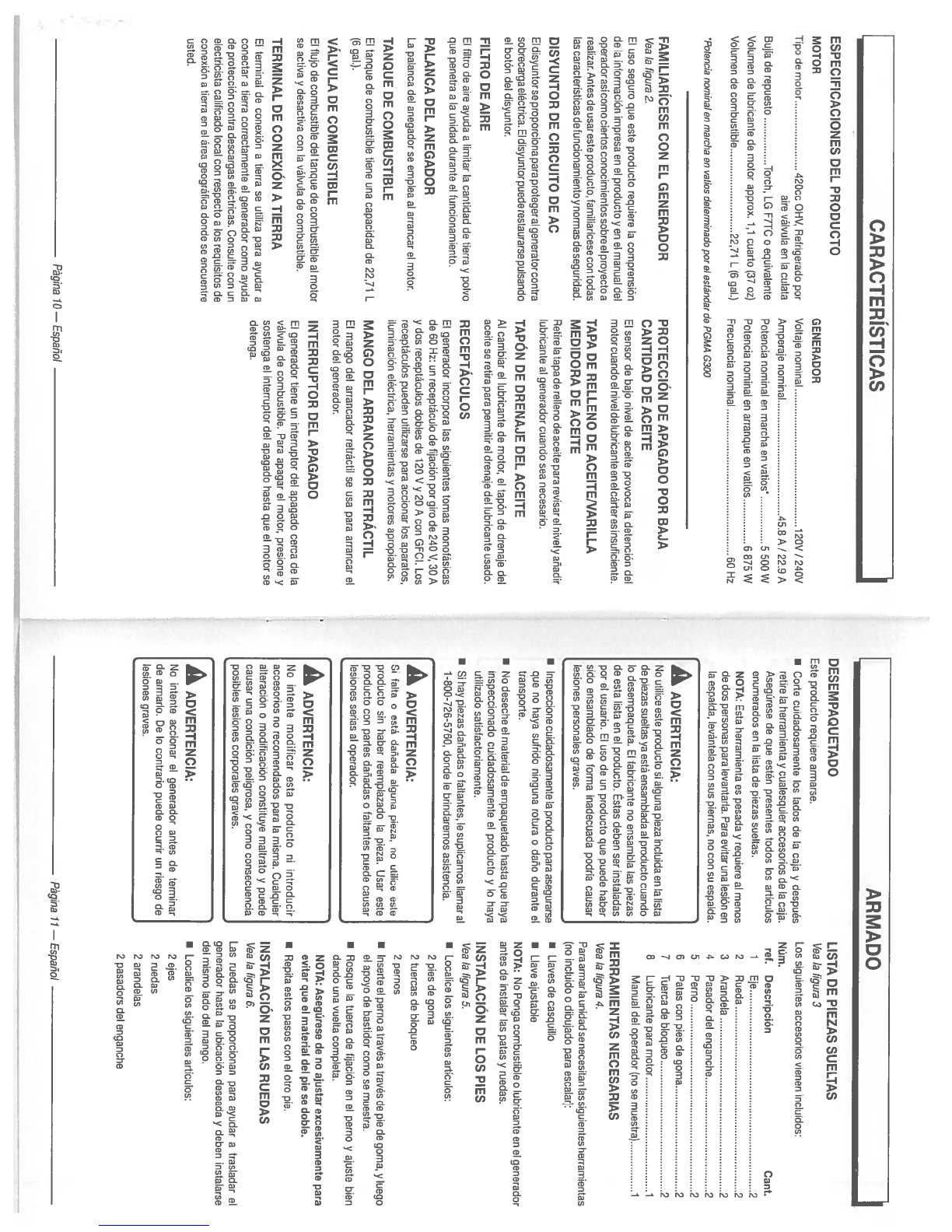
ESPECIFICACIONES
DEL
PRODUCTO
FAMILIARICESE
CON
EL
GENERADOR
Vea
Ia
figura
2.
El
uso
seguro que
este
producto
requiere
a
comprensian
de
Ia
intormaciOn
impresa
en
el
producto
yen
el
manual
del
operadorasicomo
ciertos
conocimientossobre
el
proyecto
a
realizar.
Antes de
usareste
producto,
familiaricese con
todas
as caracteristicas
de
funcionamiento
y
normas
de
seguridad.
DISYUNTOR
DE
CIRCUITO
DE AC
El
disyuntorse
proporciona
para
protegeral
generatorcontra
sobrecarga
eléctrica.
El
disyuntorpuede restaurarse
pulsando
el
botOn
del
disyuntor.
FILTRO DE
AIRE
El
filtro
de
aire
ayuda
a
limitar
Ia
cantidad
de
tierra
y
polvo
que
penetra
a
Ia
unidad
durante
el
funcionamiento.
PALANCA
DEL
ANEGADOR
La
palanca
del
anegador
se emplea
al
arrancar
el
motor.
TANQUE
DE
COMBUSTIBLE
El
tanque
de
combustible
tiene
una
capacidad
de
2271
L
(6
gal.).
VALVULA
DE
COMBUSTIBLE
El
flujo
de
combustible
del
tanque
de
combustible
al
motor
so
activa
y
desactiva
con
Ia
välvula
de
combustible.
TERMINAL
DE
CONEXION
A
TIERRA
El
terminal
de
conexiOn a
tierra
se
utiliza
para
ayudar
a
conectar
a
tierra
correctamente
el
gerrerador
como
ayuda
do
protecciön
contra
descargas
eléctricas. Consulte
con
un
electricista
calificado
local
con
respecto
a
los
roquisitos
de
conexión
a
tierra
en
el
area geografica
donde
se encuontre
usted.
PROTECCION
DE
APAGADO
POR
BAJA
CANTIDAD
DE
ACEITE
El
sensor
de
bajo
nivel
de
aceite
provoca
Ia
detenciOn
del
motorcuando
el
nivelde
lubricanteen
el
cárteres
insuficiente.
TAPA DE
RELLENO
DE
ACEITENARILLA
MEDIDORA
DE
ACEITE
Retire
Ia
tapa
de
relleno
de
aceite
para
revisar
el
nivel
y
anadir
lubricante
al
generador
cuando
sea
necesarlo.
TAPON
DE
DRENAJE
DEL
ACEITE
Al
cambiar
el
lubricante
de
motor,
el
tapón
de drenaje
del
aceite
se
retira
para
permitir
el
drenaje
del
lubricante
usado.
RECEPTACULOS
El
generador
incorpora
las
siguientes
tomas monotásicas
de
60
Hz:
un
receptáculo
de
fijación
por
giro
de
240
V,
30
A
y
dos
receptáculos
dobles
de
120
V
y
20
A
con
GECI.
Los
receptaculos
pueden
utilizarse
para
accionar
los
aparatos,
iluminaciön
eléctrica,
herramientas
y
motores
apropiados.
MANGO
DEL
ARRANCADOR
RETRACTIL
El
mango
del
arrancador
retrãctil
se usa
para
arrancar
el
motor
del
generador.
INTERRUPTOR
DEL
APAGADO
El
generador
tiene
un
interruptor
del
apagado
cerca
de
Ia
válvula
de
combustible.
Pars
apagar
el
motor,
presione
y
sostenga
el
interruptor
del
apagado
hasta
que
el
motor
se
detenga.
DESEMPAQUETADO
Este
producto
requiere
armarse.
•
Cone
cuidadosamente
los
lados
de
Ia
caja
y
despues
retire
Ia
horramienta
y
cualesquier
accesorios
de
Ia
caja.
Asegurese
de
que
estén
presentes
todos
los
articulos
enumerados
en
Ia
lista
de piezas
sueltas.
NOTA:
Esta
herramienta
es
pesada
y
requiere
al
menos
de
dos personas
pars
levantarla.
Para
evitar
una
lesion
en
Ia
espalda,
levántela
con
sus
piernas,
no
con su
espalda.
•
Inspeccione
cuidadosamente
Ia
producto
pars
asegurarse
quo
no
haya
sufrido
ninguna
rotura
o
daño
durante
el
transporte.
•
No
deseche
el
material
de
empaquetado hasta
que
haya
inspeccionado
cuidadosamente
el
producto
y
10
haya
utilizado
satisfactoriamente.
I
Si
hay
piezas
danadas
o
faltantes,
le
suplicamos
Ilamar
al
1-800-726-5760,
donde
le
brindaremos
asistencia.
LISTA
DE
PIEZAS
SUELTAS
Vea
Ia
figura
3
Los
siguientes
accesorios
vienen incluidos:
Cant.
Eje
2
Rueda
2
Arandela
2
Pasador
del
enganche
2
Perno
2
Patas
con pies
de
goma
2
Tuerca
de bloqueo
2
Lubricante
para
motor
1
Manual
del
operador
(no
se
muestra)
1
HERRAMIENTAS
NECESARIAS
yea
Ia
figura
4.
Para armar
a
unidad
se necesitan
las
siguientes
herramientas
(no
incluido
o
dibujado para
escalar):
•
Llaves
de
casquillo
•
Llave
ajustablo
NOTA:
No
Ponga
combustible
o
lubricante
en
01
generador
antes
de
instalar
las
patas
y
ruedas.
INSTALACIöN
DE
LOS
PIES
yea
Ia
figura
5.
•
Localice
los
siguientes
articulos:
2
pies
do
goma
2
tuercas
de
bloqueo
2
pernos
•
Inserte
el
porno
a
travës
a
través
de
pie
de
goma,
y
luego
el
apoyo de
bastidor
como
se
muestra.
•
Rosque
Ia
tuerca
de
fijaciOn
en
el
perno
y
ajuste
bien
dando
una
vuelta
completa.
NOTA:
AsegUrese de
no
ajustar
excesivamente
para
evitar
que
el
material
del
pie
se
doble.
•
Repita
estos pasos
con
el
otro
pie.
INSTALACIÔN
DE
LAS
RUEDAS
Vea
Ia
tigura
6.
Las
ruedas
se
proporcionan para
ayudar
a
trasladar
01
generador
hasta
Ia
ubicaciOn
deseada
y
deben
instalarse
del
mismo
lado
del
mango.
•
Localice
los
siguiontes
articulos:
2
eies
2
ruedas
2
arandelas
2
pasadors
del
enganche
Pagina
1O—Espanol
I
Pagina
71
—
Espanol
CARACTERISTICAS
I
MOTOR
GENERADOR
Tipo
do
motor
420cc
OHV,
Ref
rigerado
por
Voltaje
nominal
1
20V
I240V
aire välvula en
Ia
culata
Amporaje
nominal
45.8
A
/
22.9
A
Bulia
de
repuosto
Torch,
LG
F7TC
o
equivalente Potoncia
nominal
en
marcha
en
vatios
5
500W
Volumen
do
lubricanto
do
motor approx.
1,1
cuarto
(37
oz)
Potoncia
nominal
en
arranque
on
vatios
6875W
Volumen
do
combustible
22,71
L
(6
gal.)
Frecuoncia
nominal
60
Hz
?otencia
nominal
en marcha en
vatios
delerminado
por
el
estándar
de
PGMA
G300
ARMADO
NUm.
ref.
Doscripciön
2
3
4
5
6
7
8
A
No
utilico
oste
producto
si
alguna
pieza
incluida en
Ia
lista
de
piezas suoltas
ya
ostã onsamblada
al
producto
cuando
Ia
desompaqueta.
El
fabricante
no
onsambla
las
piezas
do
esta
lists
en
el
producto. Estas
dobon
sor
instaladas
por
el
usuario.
El
uso de
un
producto
que
puodo
haber
sido
ensamblado
de
forma
inadecuada
podria
causar
lesiones
personalos
graves.
A
Si
falta
o
está danada
alguna
pioza,
no
utilico
osto
producto
sin
haber
roemplazado
Ia
pioza.
Ussr
este
producto
con
panes
dañadas
0
faltantes
puode
causar
lesiones
serias
al
operador.
A
No
intonto modificar
osta producto
ni
introducir
accesorios
no
rocomendados
para
Ia
misma.
Cualquier
alteraciOn
0
modificaciOn
constituyo maltrato
y
puodo
causar
una
condiciOn
poligrosa,
y
como
consecuencia
posibles
losionos
corporalos
graves.
A
No
intonte
accionar
01
generador
antos
de terminar
de
armarlo.
Do
lo
contranio
puode
ocurrir
Un
riesgo
do
lesiones graves.

A
Monóxido
de
carbono.
Usat
un
generadoren
el
interior
CO
MATARA EN
POCOS
MINUTOS.
Los
gases
de
escape
del
generador
contienen
niveles
altos
de
monOxido
de
carbono
(GO),
un
gas
venenoso
que
no
puede verse
ni
olerse.
Si
puede
oler
los
gases
de
escape
del
generador,
está
respirando
CO.
Poro
incluso
sE
flO
puede
oler los
gases
de
escape,
es
posible
que
estë
rospirando
CO.
I
Nunca
use
un
genorador
dentro
de
su
hogar,
garaje,
sótano,
ni
demis
ospacios
parcialmente
encerrados.
En
dichos
espacios,
pueden acumularse
niveles
mortales de monöxido
do
carbono.
Usar
un
ventilador
a
abrir
puertas
y
ventanas
NO
proporciona
suficiente
aire
fresco.
U
SOLO utilice
el
generador
al
aire
libre
y
lejos
de
ventanas, puertas
y
respiradoros abiertos.
Estas
aberturas
pueden
atraer
los
gases
de
escape
del
generador.
Incluso
si
utiliza
el
generador
correctamente,
el
CO
puede
ingresaren
su
hogar.
SIEMPRE
utilice
una
alarms de
CO
de
pilas
o
con
pilas
do
respaldo
en
su
hogar.
Si
comienza
a
sentirse
descompuesto,
mareado
o
débil
luego
de
que
el
generador
estuvo
funcionando,
trasládese adonde
haya
aire
fresco
INMEDIATAMENTE.
Vea
a
un
doctor.
Puedo
sufrir intoxicaciOn
por monöxido
de
carbono.
APLICACIONES
Este
generador
está
disenado
para suministrar
alimentacion
elëctrica para
el
funcionamiento
do iluminación
eléctrica
compatible,
electrodomësticos,
herramientas
y
cargas
de
motor.
ANTES
DE
ACCIONAR
LA
UNlOAD
•
SOlo
utilicelo
AL
AIRE
LIBRE
y
guarde
una
distancia
al
monos de
6
m
(20
pies)
alejado
do
ventanas, puertas
y
orificios
do
ventilaciön
segün
lo
recomendado
par
el
Departamento
do
Salud
y
Servicios
Humanos
y
pot
los
Centros
para
el
Control
y
Ia
Prevención
do
Enfermedades
de
los
Estados
Unidos.
Las
condiciones
particulares de
su
casa
o
del
vionto
puede
requerir
una
distancia
adicional.
•
NUNCA
louse
dent
to
do
su
hogar
o
del
garaje,
INCLUSO
con
las
puertas
y
las
ventanas
abiertas.
•
Coloquo
siempre
el
gonerador
sabre
una
superficie
firmo
plana.
REQUISITOS
ESPECIALES:
Es
posible
quo
se
apliquen
reglamentaciones
do
Ia
AdministraciOn
do
Salud
y
Seguridad Ocupacional
(Occupational
Safety
and
Health
Administration,
OSHA)
generalos
a
estatales,
cOdigos
u
ordenanzas
locales
al
uso
para
el
quo
fue
diseñado
el
generador.
Consulte
a
un
electricista
calificado,
a
un
inspector
de
instalaciones
eléctricas
oa
a
agoncia
local
con
jurisdicciOn:
•
En
algunas areas,
so
deben
registrar
los
generadoros
en
las
respoctivas
companias
do
servicios püblicos locales.
•
Si
01
genorador es
utilizado
en
una
obra
on
construcciön,
es
posible
quo so
deban
tespetar
reglamentaciones
adicionalos.
LEVANTAR
Y
BAJAR
EL
MANGO
yea las
figuras
7y
8.
•
Para levantar
el
mango (pars
trasladar
Ia
generador):
tire
del
mango hacia
arriba
hasta
quo
Ia
perilla
do
IiberaciOn
del
mango
do
aseguramiento
paso
a
travës
dela
tanura
corrospondiente
y
inserto
Ia
clavija do
bloqueo
del
mango
para
asegure
el
mango
en
su
lugar.
•
Pats
bajar mango
(para
guardar
o
transportar
Ia
generador): quite
Ia
clavija
do
bloqueo
del
mango,
tire
do
Ia
perilla
do
liboraciOn
del
mango
y
ponga
el
mango
en
posiciOn
hacia abajo.
NOTA:
Si
recibe
un
manual
del
motor
para
este
producto,
respete
el
instrucciones
quo
se
indique
on
el
manual
del
motor
y
no
Ia
informaciOn
quo
figura
a
continuaciOn.
El
lubricante
do
motor
empleado
os
un
factor
do
gran
importancia
en
01
rondimiento
y
vida do
sorviclo
del
motor.
Para
uso
general,
a
todas
temperaturas,
so
rocomienda
el
aceite
SAE
1OW-30.
Siempre
utilico
lubricante
pata
motor
do
cuatto
tiempos
quo
satisfaga
a
sobrepaso
los
roquisitos
SJ de
clasificaciOn
de
servicio
API.
Esto
motorvienecon
una
caracteristicaqueapagara
el
motor
cuando
no
so
mantiene
el
nivel
especifico
do
lubticanto.
El
motor
volvorá
a
arrancar
hasta
quo
so
alcanco
el
nivel
adecuado
do
lubricante.
NOTA:
El
lubricante
sin
detergente
0
para
motor
do
dos
tiompos
dana
el
motor,
pot
10
cual
no
dobo
usarse.
•
Desenrosque
Ia
taps
do
relleno
do
aceite/varilla
modidora
do
acoito
y
retirela.
•
Limpie
Ia
varilla
do
nivel
y
vuelva
a
asontarla
en
el
agujoro;
no
Ia
enrosque.
•
Retire do
nuevo
Ia
varilla
medidora
do
aceito
y
verifique
el
nivel
do
lubricante.
El
nivel
do
acoite
siompro
debo
estar
entre
las
areas
cubierta
con
rayas
ontrecruzadas
do
Ia
varilla
medidora.
•
Si
estã
bajo
el
nivel,
abastezca
do
lubricanto
el
motor
hasta
quo
01
nivol
del
fluido
alcanco
Ia
parto
superior
do
Ia
varilla.
•
Vuelva
a
colocar
Ia
tapa
do
relleno
do
acoito/varilla
medidora
do
aceite
y
asogirola.
USO
DE
ESTABILILZADOR
DE
COMBUSTIBLE
El
combustible se
haco
viojo,
so
oxida
y
doscompono
al
paso
del
tiompo.
Agregando
ostabilizador
do
combustible
(no
incluido)
se
prolongs
Ia
vida
Util
del
combustible
y
so
ovita
a
formaciOn
do
depOsitos,
los
cuales
puodon
tapar
el
sistemadolcombustible.
Siga
las
instrucciones
delfabricante
del
estabilizador
do
combustible
en
cuanto
a a
debida
proporcion
estabilizador-combustiblo.
•
Vierta
el
estabilizador
on
el
tanque
do
combustible
y,
después,
Ilénelo
do
gasolina
do
conformidad
con
las
instmcciones
anteriores.
NOTA:
Pueden
mozclarso
01
estabilizador
y
Ia
gasolina
antes
do
Ilenar
el
tanque;
para
ello
utilice
una
lata do
gasolina
u
otro
recipiente
aprobado pars
combustible
y
agitela
suavemente pata
realizar
Ia
mozcla.
•
Coloque
do
nuevo
Ia
tapa
del
tanque
do
combustible
y
asegürola.
•
Atranquo
el
motor
y
dëjelo
funcionar
par
10
menos
cinco
minutos para
permitir
que
el
estabilizador
ttate
todo
el
sistema
do
combustiblo.
ARMADO
I
•
Eleve
el
oxtremo
del
genetador opuesto
al
arrancador
U
Empujeelpasadordeenganchehaciaadentrodelagujero
retrãctil
hasta
a
altura suficionto
pats
obtoner
acceso
a
del
extromo
del
eje
pars asegurar
ol
conjunto
do
las
Ia
parte
inferior
del
bastidor;
coloque
firmemente
cunas
ruodas.
debalo
para
apoyarlo.
NOTA:
Debe
introducirse
el
pasador
do
enganche
en
el
•
Inserte
el
eje
a
través
del
centro
de
Ia
rueda.
ojo
hasta
quo
01
centro
do
aquel
doscanse
en
Ia
parto
•
Coloque una
arandela
en
el
ejo,
luego
deslice
el
010
por
superior
do
Oste.
el
soporte
en
el
bastidor.
a
Para
instalar
Ia
segunda
rueda
pars
ol
otto
lado,
repita
el
procodimiento.
FUNCIONAMIENTO
FUNCIONAMIENTO
I
A
No
permits
quo
su
familiarizaciön
con
este
producto
10
vuelva
descuidado.
Tenga
presento
quo
un
descuido
do
Un
instante es
suticiente
para
causar
uns
lesiOn
grave.
A
No
utilice
nlngón
aditamento
o
accesorio
no
recomendado
pot
el
fabricante
do
este
producto.
El
empleo
do
aditamentos
a
accesorios
no
recomendados
podria
causar
losiones
graves.
AVISO:
Este
producto
cuenta
con
un
parachispas
quo
ha
sido
ovaluado por
el
Sorviclo
Forestal
del
Departamonto
do Agricultura
do
EE.
UU.,
sin
embargo
los
usuarios
del
ptoducto
doben
cumplir
con
los
reglamentos
do
prevencion
do
incendios
locales,
estatales
y
federales.
Consulto
alas
autotidades
quo
correspondan. Contacto
con
el
servicio
al
cliente
a
un
cent
to
do
servicio calificado
pars
comprar
un
parachispas
do
tepuesto.
AVISO:
Antes
do
cada
uso,
inspeccione todo
ol
producto
para
detectar
partes
dahadas,
faltantes
o
sueltas, coma
tornillos,
tuercas,
pernos,
tapas,
etc.
Apriete
firmomente
todos
los
sujotadores
y
as
tapas
y
no
acciono
oste
producto
hasta
quo
todas
las
partes fsltantes
o
danadas
soan
reemplazadas.
Pongase
en
contacto
con
el
servicio
al
clionte
o
con
un
centro
do
servicio
calificado
para
tecibit
asistencia.
A
Si
esto
generador
so
utiliza
ünicamente
con
aparatos
conectados
con
cable
y
enchufe,
el
COdigo
Eléctrico
Nacional
no
oxige
que
Ia
unidad
esté
puosta
a
tierra.
Sin
embargo,
si
so
usa
el
generador
do
otra
forma,
podria
set
necesario
ponerlo
a
tierra
para reducir
el
riesgo
do
descargas
eléctricas
o
electrocuciOn. Antes
do
usar
el
generador, consulto
a
un
olectricista
calificado,
un
inspector
eléctrico
o
un
organismo
local
quo
tenga
jurisdicciOn
pats
saber
si
es necesario
ponerlo
a
tiorra
en
su
situaciön.
A
PRECAUCION:
No
intento
levantar
Ia
unidad
pot media
do
los
mangos.
Si
fueso
necesario
Z5t
01
genorador, siempro hagalo por
media
del
bastidor.
Utilice
las
técnicas
apropiadas
do
izado
pars
evitar
losiones
on
Ia
columns.
VERIFICACION
Y
ABASTECIMIENTO
DE
LUBRICANTE
Vea
Ia
figura
9.
AVISO:
Si
se intents
srrancst
el
motor
antes
de
haborse
sbsstecido
debidamente
do
lubricante podria
descomponerso
el
equipo.
Pagina
12—Espanol
Pagina 13—
Espanol

COMBUSTIBLES
MEZCLADOS
CON
ETANOL
Al
abastecer
de
gasolina
Ia
generador,
asegürese
de
que
Ia
unidad
esté
asentada
en
una
superticie
horizonal
nivelada.
Si
estã
caliente
el
motor,
permita
que se
enfrie
a
generador
durante
cinco minutos
antes
de
reabastecerla
de
gasolina.
SIEMPRE
Ilene
el
tanque
al
aire
libre
y
teniendo
apagada
Ia
máquina.
•
Ponga
Ia
välvula
de
combustible
en
Ia
posiciOn
OFF
(APAGADO).
•
Retire
lentamente
a
tapa
de
combustible.
•
Clene
el
tanque
de
combustible
hasta
una
altura
de
2,5
cm
(1
pulg.)
abajo
del
cuello
del
tanque.
I
Coloque
de
nuevo
Ia
tapa
del
tanque
do
combustible
y
asegürela.
A
ADVERTENCIA:
Apague
siempre
el
motor
antes
de
reabastecer
combustible.
Nunca
retire
Ia
tapa
de
combustible
ni
agregue
combustible
a
una
máquina mientras
el
motor
esté
en
funcionamiento
o
caliente.
Asegürese
de
que
a
unidad
esté apoyada
en
una
superficie
horizontal
y
nivelada,
y
solo
agregue
combustible
al
aire
libre.
Si
el
motor
estã
caliente,
deje
que
el
unidad
se
enfrie
durante
al
menos
cinco minutos
antes
de
reabastecer.
Vuelva
a
colocar
inmediatamente
Ia
tapa
del
tanque
despuës
de
reabastecer
y
aprietela
firmemente.
Aléjese
al
menos
9
metros
(30
pies)
del
sitio
de
carga
do
combustible
antes
de
poner
en
marcha
el
motor.
No
fume
y
permanezca
lejos
de
llamas
abiertas
y
chispas!
La
inobservancia
de
estas
instrucciones
podrian
provocar
un
incendio
y
lesiones
personales
graves.
NOTA:
Siempre
utilice
gasolina
sin
plomo
con
un
octanale
nominal
inicial
de
86
o
mayor.
Nunca
utilice
gasolina
vieja,
pasada
o
contaminada,
y
no
utilice
mezcla
de
aceite
y
gasolina.
No
permita
que
entre
tierra
o
agua
en
el
tanque
de
combustible.
No
use
combustible
E85.
ARRANQUE
DEL
MOTOR
Vealas
figures
ha
13.
[AVISO:
Teniendo
Ia
unidad
en
una superficie
nivelada
y
con
el
motor
apagado,
revise
el
nivel
de
lubricante
cada
vez
[antes
de
usar
el
generador.
NOTA:
Si
el
generador
no
estã
en
una superficie
nivelada,
es posible
que
no
arranque
o
se
apague
durante
su
funcionamiento.
•
Desconecte
todas
las
cargas
del
generador.
•
Ponga
Ia
välvula
de
combustible
en
Ia
posician
ON
(ENCENDIDO).
•
Desplace
derecha
de
Ia
palanca
del
anegador
hasta
Ia
posicion
START (ARRANQUE).
NOTA: Si
el
motor
está
caliente,
o
Ia
temperatura
es
superior
a
los
10
‘C
(50
‘F),
desplace
izquierda
Ia
palanca
del
anegador
de
Ia
posiciOn
RUN
(FUNCIONAMIENTO).
•
Tire
del
mango
del
arrancador
retráctil
hasta
que
comience
a
funcionar
el
motor.
NOTA:
No
permita
que
el
mango se
rotraiga
violentamente
despues
de
arrancar;
regreselo
suavemente
a
su lugar
original.
•
Permita que
el
motor
funcione
15-30
segundos
y,
dospués, desplace
izquierda
Ia
palanca
del
anegador
en
Ia
posicion
RUN
(FUNCIONAMIENTO).
Cualquier
establecimiento
o
técnico
de
reparaciones
caliticado
puede
realizar
el
mantenimiento
normal,
el
reemplazo
0
Ia
reparacian de
los
dispositivos
ysistemas
decontrol
de emisiones,
con
repuestos
originales
o
equivalentes.
Un
centro
de
serviclo
autonzado
deberä
realizarlas
reparacionesy
eI
retiro
del
producto
que cubra
a
gsrantia;
pongase
en
contacto
con
el
servicio
at
cliente
para
obtener
ayuda.
FUNCIONAMIENTO
I
AVISO:
No
utilice
combustibles
El
5o
E85
con
este
producto.
Esto
constituye
una
violación
ala
ley
federal,
danarã
a
unidad
y
anulará
Ia
garantia.
Utilice
ünicamente
gasolina
sin
plomo
que
contiene
hasta
10%
be etanol.
VERIFICACIÔN
V
ABASTECIMIENTO
DE
COMBUSTIBLE
Vea ía
figura
10.
A
Riesgo de
incendios
y
lesiones
por
quemaduras:
Nunca
retire
a
tapa
de
combustible
mientras
estë
encendida
Ia
unidad.
Apague
el
motor
y
deje
enfriar
Ia
unidad
durante
al
menos
cinco minutos.
Retire
Ia
tapa
lentamente.
A
La
gasolina
ylos
vapores
be
Ia
misma son
extremadamente
inflamables
y
explosivos.
Pars
evitar
losiones
y
daños
fisicos
serios, maneje
con
cuidado
Ia
gasolina.
Mantengala
lejos
de
fuentes
de
ignicibn,
manejela
solamente
al
aire
libre,
no
fume
mientras
vierta
Ia
gasolina
y
limpie
de
inmediato
cualquier
derramamiento que
ocurra.
FUNCIONAMIENTO
APAGADO
DEL
MOTOR
I
Permits
un
periodo
de
enfriamiento
do
30
minutos
antes
de
Vea
ía
figura
13.
guardar
Ia
mãquina.
Para
apagar
el
motor
en
condiciones
normales
de
•
Para
seguridad, inserts
el
pasador
do
seguro
del
mango
funcionamiento:
para
asegurar
el
mango
antea
de
traslado.
•
Desconecte
del
generador
toda
carga
presento.
NOTA:
Para ayudar
a
quo
01
pasador
do
bloqueo
del
mango
I
Ponga
Ia
válvula
de
combustible
en
Ia
OFF
so
mantenga
firme
en
el
orificio,
empuje
el
area
acoplada
(APAGADO).
del
acollador
hacia
el
interior del
armazön
del
generador.
•
Presiono
y
sostenga
el
interruptor
del
APAGADO
hasta
quo
I
Con
su
pie
en
Ia
parte
trasera
del
bastidor,
incline
Ia
miquina
el
motor
so
detenga.
hacia ustod
hasta
quo
se
equilibre
en
las
ruedas,
luego
Para
apagar
el
motor
en
una
situacidn
de
emergencia:
empuie
Ia
maquina
ala
posicion
besoaba.
•
Presiono
y
sostenga
el
interruptor
del
APAGADO
hasta
quo
LEVANTAR EL
GENERADOR
01
motor
so
detenga.
Vea
ía
figura
75.
•
ApsgUe
Ia
generador.
A
ADVERTENCIA:
•
Pliegue
el
mango
hacia abajo.
Nunca
alce
o
mueva
oste
Tanto
en
funcionamiento
como
al
guardarlo,
mantenga
producto toméndolo
por
el
mango
movil.
siempre
91,4
cm
(3
pies)
be
eapacio
libre
en
todos
los
NOTA:
Eata
herramienta
es
pesada
y
requiere varios
perso
laterales
do
este
producto,
incluida
Ia
parte
superior.
nas
a
levantar.
Para
evitar
lesionarse
Ia
espalda,
mantonga
Aguarde
al
menos
30
minutos
para
el
equipo
se
enfrie
antes
bobladas
las
rodillas,
levante con
las
piernas,
no
con
Ia
be guardsrlo.
El
cater
generado
por
el
silenciabor
y
los
gases
espalda,
y
obtenga
ayuda
cada
vez
que
Ia
necesito.
be
escape
puede
ser
suficiente para
causar
quemaduras
OPERACION
A
ALTITUDES
ELEVADAS
graves
yb
prondor
fuego
a
objetos combustibles.
_________________________________________________
Su
motor
esté
configurado
pars
funcionar por dobajo
do
los
609,6
m
(2
000
pies)
be
altitub
mebibos
en
Ia
fábrica.
Su
TRASLADO
EL
GENERADOR
motor
se
dobo
volver
a
configurar
para
funcionar por
sobre
Vea
ía
figure
74.
los
609,6
m
(2
000
pies)
de
altitud.
Hacer
funcionar
el
motor
•
Apague
Ia
gonerador.
con
Ia
configuración
equivocaba
a
determinaba
altura
puede
•
Levante
el
mango.
aumentar
las
emisionea,
reducir
Ia
eticioncia
del
combustible,
•
Desconecte todos
los
equipoa
quo
eaten
enchufados
al
perjudicar
01
funcionamiento
y
provocar
daños
irreversibles
al
generador.
motor.
Los
motores
quo
eaten
configurabos para
funcionar
en
una
altitud
alta
no
so
puoden
utilizar
en
condiciones
do
altitud
•
Ponga
Ia
válvula
do
combustible
en
Ia
posicidn
OFF
esténdar.
Un
centro
do servicio calificado
debe
asegurarlo
quo
(APAGADO).
su
motor
está
debidamento
contigurado
para
funcionar
donde
usted so encuentro.
MANTENIMIENTO
I
A
Al
dar
sorvicio
a
Ia
unidad, solo
utilice
piezas
be
repuesto
recomendadas
o
equivalontea.
El
empleo
de
piezaa
diferentes
podria
causar
un
peligro
o
danar
el
producto.
A
Antos
do
inspeccionar,
limpiar
o
bar
seivicio
a
Ia
maquina,
apague
el
motor,
eapere
a
quo
so
dotengan
todaa
las
piezaa
en
movimiento,
deaconecte
el
cable
be
Ia
bujia
y
aléjelo
do
éata
.
Permits
un
periodo be
enfriamionto
de
30
minutos
antes
do
efectuar
cualquier
tarea
be
mantenimiento.
El
incumplimiento
do
cualquiera
do
estas
inatrucciones
puede
causar
lesionos
fisicaa
graves
o
danos
a
Ia
propiedad.
AVISO:
Inspeccione
poriddicamonto
tobo
01
producto
pars
detectar
patios
danadas,
taltantes
o
sueltas,
como
tornillos,
tuercas,
pernos,
tapas,
etc.
Apriote
tirmemente
todos
los
sujetadorea
y
las
tapas
y
no
accione esto
producto
hasta
quo
todas
las
partea taltantes
o
banadas
sean
reemplazadas.
POngase
en
contacto
con
el
aervicio
al
cliento
o
con
un
contro
do
sorvicio
calificado
pars
recibir
asistoncia.
Pagina
74—Espanoí
PAgina
15— Espanoí
Other manuals for BM905500
1
Table of contents
Languages:
Other Black Max Inverter manuals

Black Max
Black Max BM907500BT User manual

Black Max
Black Max BM907500BT User manual

Black Max
Black Max BM903650 Series User manual

Black Max
Black Max BMi2100 Series User manual

Black Max
Black Max BM907500BT User manual

Black Max
Black Max BM903500 User manual

Black Max
Black Max BM903655DA User manual

Black Max
Black Max BM903600 User manual

Black Max
Black Max BM10700 User manual

Black Max
Black Max BMi1000 User manual


