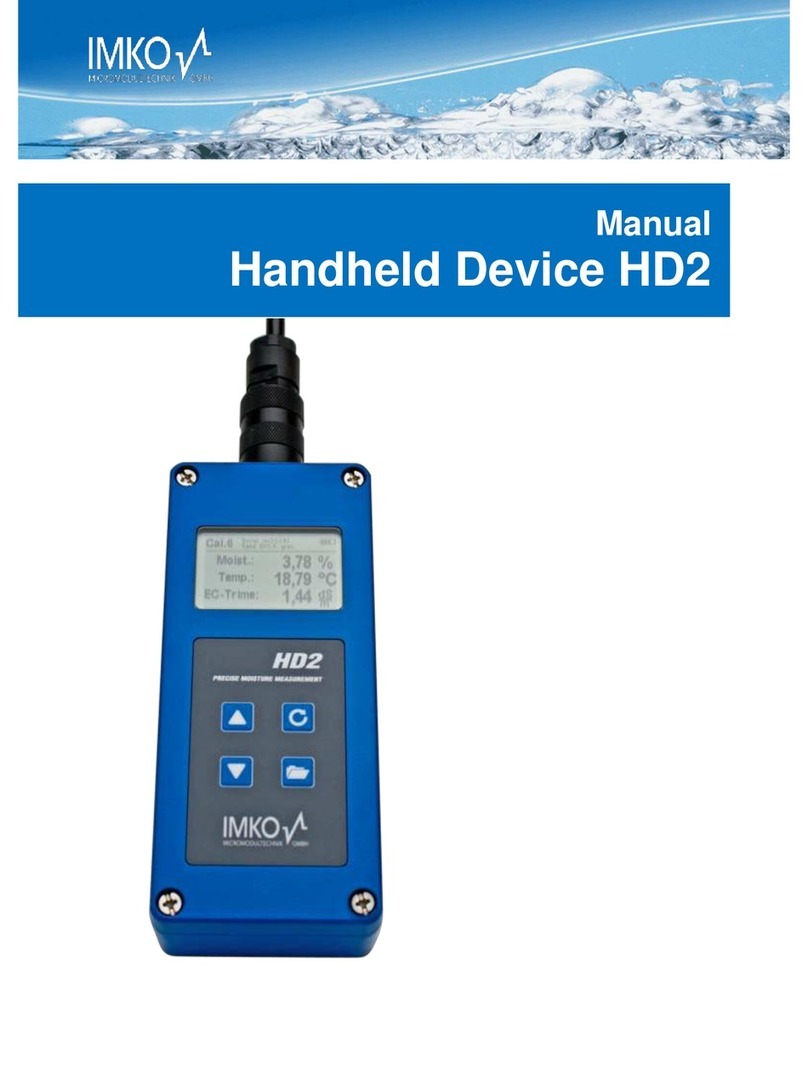
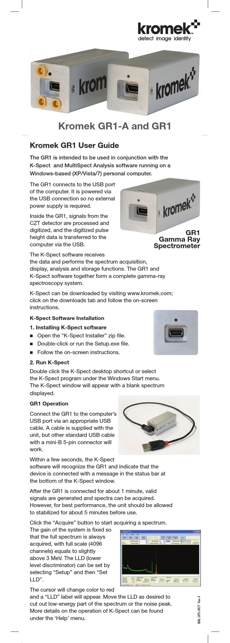
BLACK STAR METEOR 600 User manual

H E sirEBr^r??^....,..".-.,-...
ffi H
BIack*Sfdr
METEOR
SERIES
DIGITALFREOUENCY
COUNTERS
METEOR
1OO
METEOR
600
METEOR1OOO
ffiHmam O
_ _ '--a
HEY'.'-'H1e??,,W€
Instruction
Manual

INDEX
SPECIFICATION
FRONT
PANEL
LAYOUT
BACK
PANEL
LAYOUT
MAXIMUM
INPUT
VOLTAGES
INSTALLATION
MAINSADAPTOR/CHARGER
POWERAND
BATTERIES
RANGE
GATE
TIME
LOWFREOUENCYFILTER
INPUTS
INPUT
IMPEDANCE
TERMINATION
ANDUSEOFPROBES
TRIGGER
LEVEL
DISPLAYS/INDICATORS
EXTERNAL
REFERENCE
OSCI
LLATORFACI
LITY
TRANSMITTER
FREOUENCYMEASUREMENT
RECEIVERFREOUENCYMEASUREMENT
MAINTENANCEANDREPAIR
CALIBRATION
GUARANTEE
Page
2
3
3
4
5
5
5
6
6
7
7
7
7
8
8
B
10
10
11
11
O 1983BLACKSTAR
LTD.

TETEOR SERIES A-DIGIT FFEQUE]ICY COUIiITERS
SPECtFtCATtOIrS
TETEOR lOO TETEOR
60() TETEOR IOOO
FREqUENCY RANG€ 5Hz 1O0MHz
{Typ,cally2H2 ro 120MHz)
Sw rch seleclable,^ 2 ranss w,lh rh,r
ranoefor +10 prescaler
oprion
5Hz - 60OMHz
(Tvp,cally 2Hz, ?O0MHzl
Swrrch
selectable,n3 ranges
5Hz lOOoMHz
lTyp,cally
2Hz ' l.2cHr)
Swrrchselectablein 3 ranges
M€ASUREMENT ACCUBACY i l1 count + trmebase
accuracy)
TIMEEASE
Crysl.l Os.illaior Frequ€ncy IOMH2
<iO5PPm
Fuliy Glibrated berore
leavng tactory. Front panel
acc6s for any fulure adlusimenr
femtsrarure Stab'hay TypLcally <+ 2.5ppm lrom + lOoC ro + 40oC
AsiD9
Tihe hrween Me.su.ements 20o mS
GATE TIM€S 0.1 sec..1 sec.,10 sec
.sw tch selectabl€
w,th L E D. Care
srarss
indicat,on
LOW FBEOUENCY llnput A) 5Hz
- 10MHzjloMHz - l00MH,
IMo//30pi nom. (Low Frequency F,rt€r
- Oul')
Maxrmud Inpur Volla$ 5OVDC or 250V ,ms (i 50Hz decreasrns
lo 5V rms @
70kHz aod above
IOMHZrange
:< 5mV 5Hz
- l0MH2
IOOMHZrange:
< lomv IOMHZ 50MHz
< 25mV 50MHz
- lOoMHZ
loMHz Range 1OH2
-
0.1 sec Gate T16e
1H2 1 sec.Gare
T,me
0.1
Hz - 10 secGare
Time
IOOMHz Ranse lOoHz ' O.1sec
Gate T,me
lOHz - 1 lec GateT,me
I Hz - l0 secGateTime
Low Frquency Filt€r Cutttr lrequency 50kHz nom. trom source
impedance
ol <50o Sw,rch selecrable'ln'o. Our'
Fronr panel
adtustment ot Tnsser Level
on siqnali
5H2 - loMHz
HIGB FREOUENCY IInput
8} ,iir,i
ii.i.lri 4OMH? - 600MHz 4OMHz
- IGHz
riiiir:tfiiiiLi.,,,,:,:. 50onom
Maxim0m Inpur Volta$ t'iiffi 50VDC or 25OV rm! LdSOHZ
decreasrns
ro 2V rms a4
50MHz and above
<25mV 40MHz ro 6O0MHZ <25mV 4OMHz 6OOMH2
<5OmV upro lGHz
..li lkHz-O.l sec.GareTrm€
100H2 - 1 sec GateT,me
10Hz - l0 rec.Gate Time
GENEBAL a - D,9,r0.5 7 sesmenr L.E.D. Displayw,lh aulomar,c decimal pornr
and leadins
zero
suppress,on
Frequency unrr {kHz or MHz) indical,on by L.E.D. and Overflow warning bv L.E.O.
Powe. Sequ'remenR 9V OC Cd
(max) 6OOnA Operarion
bv Ma,nr Adapro/Charger Guppliedl or 6 x Nl-CAO C'Cells {opt,onal)
Typicalry6 hours (lOOMHz range
usins1.2Ah cerls)
'On'or'OJf 5OmA nom. I 'Fasl Charse'
340mA nom
EnYr.ohmenral
oFrating rans OoC ro +aooc (10% 80% aH non-condenr,ng)
Clsrom moulded,3rurdv, l,ghtwer!hr A B S wrrh r'11 5land and 'nternal baller
Size 2t9mn,240mmr98mmlProdlcronlv) 321mmt352mmx174mm(Packed)
980s lP.oducr onryl L9K9 (Pa.ked)
SuDtlicd Ac6o'r!5 MarnsAdaplor/CharWr dnd Insrrucrion Ma^ual
Opr'onalAcc6ones Ser Nl CAD Rechargeable
Cells Telescopic
R.F. Pick up Anlenna
PasrveProb€s INC _a-N.C.CoaxLeads
Errernal Eelerence
Inpur Fac,l,ry (10Mhzl Service
Manu€r

FRONT
PANELLAYOUT
1 Power
Switch
2 RangeSwitch
3 GateTimeSwitch
4 GAIE
T|MELED
5 Calibration
Access
6 BNCSocketInputB
(6O0MHz
andlGHzmodelsonly)
7 BNCSocket
InputA
8 LowFrequencyFilterSwitch
I TriggerLevel
Control
BACKPANELLAYOUT
@
10 LEDindicates
display
inkHz
11 LEDindicatesdisplay
inMHz
12 Frequency
Display
13 LED-Overflow
indication
14 BaneryCompartment
15 Mains
Adaptor/ChargerInput
16 BNC
Socket-lnput forEldernalBelerence
Oscillator
] Ootional
17 Switch-External Reference
Oscillator J

MAXIMUM INPUT VOLTAGES
Do not applymore
than50V
DCor250V
r.m.s.
sinewave@ 50Hzto any
signal
input.
Forotherfrequencies
see
graphs:
INPUT
A 5Hz-100MHz
250V
50
Hz
MAXIMUM
INPUT
VOLTS
RMS 5V 50kHz
10
5
100 1K 10K 100K
1M
INPUTFREOUENCY
INPUT
B 40MHz
10M 100M
Hz
- lGHz
1000v
7Sn
100
250V
501-lz
250V
500H2
MAXIMUM
INPUT
VOLTS
RMS 10
52V50MHz
100 1K 10K
100K
1M 10M
100M
1G
INPUTFREOUENCYHz
n.l 1 10

INSTALLATION
(a) Insertcells
and/or
mains
adaptor.
(Backpanel(14)
or
(15).)
(b) Move
power
switch
(1
)
to 'On'.
(c) Select
range
(2)
required,ifknown.
(d) Connectsignaltobemeasuredtoappropriate
input.
((6)
or
(7).)
(e) Select
gate
time
(3)
required.
Wait
for
one
gate
period.
(See
LED
(4).
)
MAINSAOAPTOR
TheMains
Adaptorsuppliedhas
beenspecially
designedto power
your
Meteor
Frequency
Counter.
lt issuitable
for
the
normalmains
supplyinthecountryof
purchase.
lt is NOT protectedagainstcontinuous
short circuit but will
cause an internal
nonresettable thermaltripto operate.NOOTHER
MAINS
ADAPTOR(EVEN
IF APPARENTLYIDENTICAL)
MAY BE USEDON A
METEORFREOUENCY
COUNTER.Suchuse
willinvalidatetheguarantee
and
may
damagethecounter.
POWERAND BATTERIES
Switch
(1).
Thishasthree
oositions:
'Fast
Charge'willre-charge
fully
discharged
cellsat the maximum
ratecon-
sistent with not overloading
the mains adaptor. There is no provision
for
sensing
fully chargedcells
and the usermust satisfyhimselfthat useof this
facility
will not overcharge,overheat
or otherwisedamagethe cells
inuse.Do
not usein thisposition
for morethan one hourand then only on fully
dis-
charged
cells.
'Off' disablesthe instrumentbut allowstrickle-chargingof the cells.Nickel-
Cadmiumcellsof at least
1.2ampere-hour
capacitymay be safely
trickle-
chargedindefinitely
in
this
position.
'On' applies
powerto the instrumentfrom internal
cellsor preferentially
from
the mains
adaptor
if used.lf the mainsadaptorisused
with thecells
in place,
the cellswill betrickle-chargedas in 'Off'. lt is
specifically
recommended
that
primary
(dry)
cellsarenot used,
whetheralkalineor other
types. lf, however,
theyareused,they MUST be removed
before
connecting
the mains
adaptor.
Damage
caused
byuseof drycellsis
notcovered
bytheguarantee.
RANGE
Switch (2). Thishas
three
positions:
'10MHz'selects
the 10MHzrange.
Any signalof sufficientstrength
may be
readfrom 5Hz to 10MHzon this range,but see 'Low FrequencyFilter'and
'Trigger
Level'below.The
signalmust
be
applied
to Input
A (7).

'100MHz'
selectsthe 100MHz
range.
Any signalof sufficientstrength
maybe
readfrom (typically)
lMHz to 100MHzonthis
range,butsee'Low Frequency
Filter'below.
The signalmustbe appliedto Input
A (7).
'Prescaler
- 10'
(Meteor
100
only).Thisbehavesexactly
thesameas
100MHz
input, but the decimalpoint is displacedto the left allowingdirect reading
whenadecade
prescaler
is
used.
'600MHz'(Meteor
600only).
Thisselectsthe 600MHz
range.
Any signal
of
sufficientstrength may be readfrom 40MHz to 600MHz
on this range.
The
signalmustbeappliedto InputB (6).
Thisrange
may
display
a reading
in
the
absenceof an inputsignal.This
isdueto exceptionalsensitivity,anddoes
not
affectoperation
oraccuracy.
'1GHz'(Meteor 1000only).Thisselects
the lGHz range.
Any signal
of suf-
ficient strengthmay be readfrom 40MHzto lGHz on this range.The signal
must
be
applied
to Input
B (6).
This
range
may
also
displayreadings
inthe
ab-
senceofan
input
signal,whichcanbedisregarded.
GATETIME
Switch (3)
.Thisswitch hasthree
positions.
Notethere
is
an interval,
between
successivemeasurements.of200ms.
'0.1s'
selectsameasurementintervalof 100ms.Maximum
resolution
10H2.
'1s'
selects
ameasurement
intervalof 1second.
Maximumresolution
1Hz.
'10s'selects
ameasurement
intervalof 10seconds.
Maximum
resolution
0.1H2.
Measurement
isinprogress
while
gate
timeLED
(4)
islit.
LOW FREOUENCY FITTER
Switch (8).
This
hastwo positions:-
'Out' by-passesthe filter circuitry
and allows
full frequencyspectrumon the
5Hz
to 100MHz
input.
'ln' introduces
a low pass
single
pole
filterintothe 5Hz
to 100MHz
input.This
filter hasa -3dB point of nominally
50kHz
when fed from a low impedance
source
giving
normalsensitivityto audiofrequencies,with sensitivity
falling
off
rapidly
above
this.
lt's
purpose
is
tofilter
out R.F.signals.
Whena
wideband-
width instrument
is
connectedto a highimpedance
low-frequency
circuit,
it is
quitecommon for parts
of the circuitunder
testto act as
aerials
for anystray
sources
of R.F. radiation.
Becauseof the high sensitivityof the instrument,
these
signals
can becountedcausingerrorsin thewanted measurement,and
f
iltering
is
themostsatisfactorysolution.
r,

t
I
I
INPUTS
Input
signal
levels
should
alwaysbe
keptto theminimum
practicable
asunder
certain
circumstances,
especially
when using
Input A {7),mismatches
can
cause
unwantedline reflections
and apparent
frequency
multiplication.
All
BNC sockets
arecompatible
with 50Q
plugs.
The useof T5rC2plugs
may give
unreliable
ornoisy
connections.
INPUT IMPEDANCE
The impedance
of Input
A isnominallylMeshuntedby 30pf.Whenthe Low
Frequency
Filterisin circuit,
thisreduces
to a series
combination
of 300eand
1
Onf.
Theimpedance
of Input
Bisnominally
50
a .
TERMINATION AND USE
OFPROBES
Input A - When measuring
frequencies
over lMHz with a highimpedance
counter, reflections
of the signal
can cause
standing
waves, miscounts
and
possible
damage
to the circuit
undertest.To prevent
this, use
a throughter-
mination
to match
the
input
cable
or,
if
thecircuit
undertestcannot
standthe
load,
use
ashort
(< 16 wavelength)
input
cable.
Use
of BlackStar Passive
Probesisrecommended
as
this minimises
thecap-
acitiveloading.
Thefollowing
areavailable
as
optional
accessories:
AT-001
- Xl probe
for any signal
up to 1MHz.The low capacitance
cable
minimises
circuitloading.
AT-010
- X10attenuator
probe
for higher
levelsignals,
wherecircuitloading
is
critical
(10M() input
impedance)
orfor signals
over
1MHz.
No terminationis
needed
and the probe will acceptsignals
up to the maximumfrequency
of
Inout
A.
AT-110
-A switchable
probe
combiningthefeatures
ofboth.
Input B Use50Qcoaxial
cable
orthe Btack
star KBS series
of BNC coax
Leads
(optional
accessories).
TRIGGER
LEVEL
The operation
of this control (9)
isanalogous
to theTrigger
Level
control on
an oscilloscope.
lt onlyoperates
on the5Hzto 10MHzrange
and enables
the
threshold
of thesquaring
circuit
to bemoved
to thepositive
ornegative
part
of
thesignalallowing
theuser
to overcome
miscounts.caused
by poor
ordistorted
input
waveforms,
ringing,
overshoot,noise
etc.

DISPLAYS/INDICATORS
The
gate
time
LED
(4)
islit
forthedurationof each
measurement
period.
The
kHz (10)
and MHz ('11)
LED'sindicatethe scalefactorof the display.The
display
(12)
hasleading
zerosuppression
(for power conservation)and auto-
matic
decimal
pointlocation.
Note
that all
of thedigits
on thedisplaymaynot
be illuminatedfor a particular
frequencyrange/gate
time combination
e.g.
600MHz0.1sec
would
displayatrangemaximum:-
O mxz
IIEENENE
The
Overflow
LED(13)willonly
lightwhen
the
mainLC ,and
hence
thedisplay,
overflows.
Thereisno over-range
indicator.
Generally
mostunitswillread
to
atleast
11oo/oofthesetrange.Typicalsymptomsoftoohigh
af
requency
input
are
extreme
variations
in reading
betweenone
gate
time
andthe next,
unex-
pectedly
lowfrequencyreadings
orlack
of input
sensitivity.
EXTERNAL REFERENCE
OSCILLATOR FACILITY {optional)
The ExternalOscillatorFacilityallowsthe use of an alternative
highlystable
10MHzfrequencystandardto improvetheperformance
oftheinstrument.
The
standardshouldbeconnected
to theExternalReference
Oscillator
lnput
(16)
on
theback
panel.
Theinputshould
have
anamplitudeof 5V peak
to peak.
The
input
impedanceis
inexcess
of 1ka butisshuntedbyabout1Opf.
Theinput
waveform
need
not be sinusoidal
but shouldbe freefrom glitches
and har-
monicripple.
(A squarewave
mayhaveslowriseandfalltimesbutshouldbe
reasonablyflat and freefromovershoot.forinstance.)
The mark/space
ratio
shouldbe ascloseaspossible
to 1:1.
TheExternal
Reference
Switch (17)
selectsbetween
internal
andexternal
refer-
ence
sources.Thisswitch
must
be
returned
tothe
'lnternal'
oosition
when
the
counter
is
being
used
in
the
normalmode.
TRANSMITTER FREOUENCY
MEASUREMENT
When measuring the frequency of a transmitter, the most serious risk
witha FrequencyCounter
is
thatof overloading
and
damaging
theinputs.lfin
doubt, assumethecounterwill beoverloaded
and
take
precautions
accordingly
(see
specif
ication).
I

The indirect
method (no physical
connection)of measuringtransmittedfre-
quency is usually the safest and most convenient. Using the Telscopic
Antenna(optional
accessory)
plugged
into
theappropriateinput
onthecount-
er,
setthetransmitterto itsminimuminputpower
and
initiallymeasure
thesig-
nalsomefive to sevenmetresfrom the transmitter
aerial.
This isusually
ad-
equate
for H.F.signals.ln tests, y4
watt attenuatedoutputfrom a C.B.trans-
ceiver
gave
stable
readingswhen fedto a 1lz metre
base
loaded
whip antenna
about 10metres
from the frequency
counter.Where low powertransmitters
with inefficient
aerials
are
used
(as
with somehand-heldtransceivers)thesep-
aration
may need
to be reduced
but, in practice,
the aerial
rarely
needsto be
closerthan 1
to 2 metres.Wherea high-power
transceiver
is
being
tested
and
the power levelcannotconveniently
be reduced,
use
theTelescopic
Antenna
fullyclosed
or a simple
pick-up
coil
of 2 or3 turns,2" indiameter
andearthed
at
oneend.
With direct connection of the transmitterto the FrequencyCounter, it is most
importantnot to exceedthe maximuminput
voltagerating.
Forexample,con-
sidera 5 watt transmitteron the amateur2 metreband radiating
at 145MHz.
Themaximuminput
is
2V rms
into
50Q(lnput
B) representing
80mW.
There-
forethe
minimum
attenuationnecessaryis
10
log
(5/0.08)
dB
or18dB.ln
prac-
tice,asthe Meteor
seriesof Frequency
Counters
are
sosensitive,
30dB
would
besafer
andstillallow
a comfortable
inputlevelof 0.5Vrms.Notethe necessity
of using
an adequatelyrated
attenuator
(5W in thiscase).InputA has
a high
input impedance
and a suitable
'through'matchingterminationshouldbe
used
when making
connectionwith coaxial
cables.
ModulatedCarriers:
F.M - NarrowbandF.M.asusedwith manymodern
communications
trans-
ceivers
should
present
noproblems
asthecounter
essentially
averages
overthe
gateperiod.
Wide bandF.M. israrelyencounteredbut should
give
acceptable
resultswith longer
gate
times.
A.M. - lt isdifficultto measure
highlymodulated
A.M. signals
as,at some
points,
the carrier
reachesverylow levels.
Further,
the mean
powermaycon-
siderablyexceedthe nominal
power, so greatcaremust be takenwhen cal-
culatingattenuationfor direct
coupling.lf thesignal
canbe measured
when
free
from modulation,
theresults
are
always
more
predictable.
S.S.B. - Single
sidebandtransmissionssuppressthe carrierwhich therefore
cannoteasilybe measured.lf anaudio
signal
generator
isavailable,transmit
a
lkHz tone and note the measuredfrequency
indicated
on the counter.Sub-
tract lkHz from this readingfor true carrierfrequency
with uppersideband
transmission
{and
viceversa
for lowersideband).
C.W. - Measurementis
straightforward.
lf usinga morse
sender,
thekeymust
bekept
depressed.

RECEIVER
FREOUENCY
MEASUREMENT
Directmeasurement
of received
frequencyinasuperhet.receiver
isnot norm-
ally
possible.
lt is
easierto measurethelocal
oscillatorfrequency
andallowfor
any
l.
F.offsets.
Forexample,
aconventionalreceiver
with
455kHzl.F.andthe
local
oscillator
sethigh
would,whentunedto B.B.
C.Radio
Threeon1.206MH2,
exhibit
a measureable
local
oscillatorfrequency
of 1.661MHz. lf the l.F.fre-
quencies
are not known, find a station
of known frequency
and measure
the
local
oscillator.
Retuneto the unknownstationandmeasure
thelocal
oscillator
again.
The differencebetween
the two measurements
isthe sameasthe dif-
ference
between
thefrequencies
of thetwo stations.
Some
modernmulti-band,
multi-mode
receivers
usedifferent
l.F. frequencies
depending
on the band
selectedwhich may renderthis techniquedifficult or impractical.
Another methodisto tune inthewanted
stationthentune
asignal
generator
-
feeding
asmall
aerial
near
the
set
-using
minimum
power,
untilanaudible
beat
with the wanted station is heard,then measure
the frequency
of the signal
generator. By using low power, the chance of spurious
beats,whistles or
'birdies'due to harmonics
or poor imagerejectionin the receiver,
isreduced.
The two strongestbeatswill normally
be at the wanted frequency
and the
imagefrequency
(offset
bytwicethe l.F.).Thebeat
atthe
wantedfrequency
shouldbestronger
andrequire
lessinjected
signal.
MAINTENANCE AND REPAIR
The manufacturer,
or the appointedagentsoverseas,
will repair
andcalibrate
anyinstrument
developing
a fault.
Seethe guarantee
cardfor full
detailsbut
always observe
thefollowing
points:-
1. Remove
batteries
beforereturning
product
2. DoNOTreturn
anyaccessories.
3. Packproduct very carefully.
Wheneverpossible
retain
original
packing
forthis
purpose.
Where
ownerswish
to undertaketheir
own repairs
andcalibration.this
should
be carried
out by skilled
personnel,
with accessto precision
equipment,
working
inconjunction
withthe
ServiceManualwhich
canbe
purchased
f
rom
themanufacturer
ortheiroverseas
aoents-

CALIBRATION
For
optimum
accuracy,
theinstrument
requires
calibration
fromtime
to time.
How frequently
will depend
on the user
and
application
but once
everytwelve
months would normally
be adequate.
provision
for this is madeon the front
panel.
Useof a nylon
trimmer
tool is
recommended.
lf ascrewdriver
is
used,it
MUSTbeinsulated
fromthefront
panel,
asashort
circuit
from
thetrimmer
to
ground
willcause
damage.
Themost
convenient
accurate
frequency
reference
is
usually
a precise
transmitted
carrier
wave.
Inthe U.K., Rugby
(60kHz)
and
Droitwich(currently
200kHz,
changing
to 198kHz
in 1986)
aresuitable
trans-
missions.'off-Air' frequency standard receivers
for this purposeare com-
mercially
available.
GUARANTEE
For
guarantee
details
please
refer
to separate
cardinserted
in
thismanual.
This manual suits for next models
2
Table of contents

