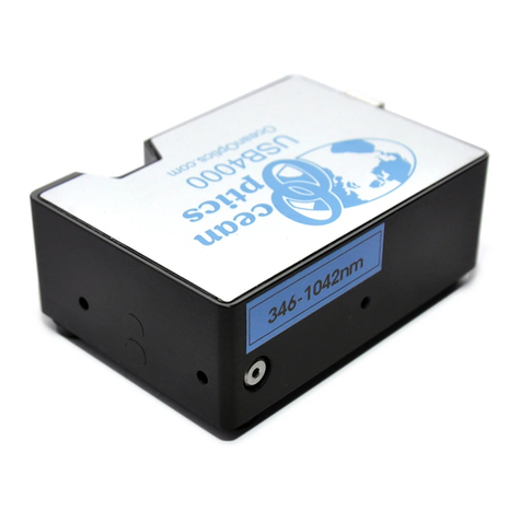
BlackHawk Labs USB560v2 User manual

Blackhawk USB560v2
System Trace Emulator
Installation Guide
USB560v2-IG-01
APRIL 2012

USB560v2-IG-01
2XBlackhawk USB560v2 System Trace Emulator
Blackhawk USB560v2 System Trace Emulator
Installation Guide
IMPORTANT IMFORMATION
© 2012 EWA Technologies, Inc. All rights reserved.
Reproduction, adaptation, or translation without prior written permission is prohibited,
except as allowed under the copyright laws.
EWA Technologies Document: USB560v2-IG-01
Warranty – this manual
The information contained in this document is subject to change without notice.
EWA makes no warranty of any kind with regard to this material, including, but not limited
to, the implied warranties of merchantability and fitness for a particular purpose.
EWA shall not be liable for errors contained herein or for incidental or consequential
damages in connection with the furnishing, performance, or use of this material.
About This Manual
This document represents the Installation Guide for the Blackhawk© USB560v2 System
Trace Emulator product (BH560v2). The BH560v2 is a device that attaches to a personal
computer or laptop to allow hardware engineers and software programmers to develop
applications with DSP’s via their computer's USB or Ethernet interfaces.
This guide contains some text paragraphs that are very important for proper device
functioning and for preventing the BH560v2 device and target board from being damaged.
These paragraphs are shaded as in the following example. Please read each of these
areas of text carefully.
Related Documents
1. Texas Instruments CCSv4 Wiki Page (tiexpressdsp Wiki - Updated: daily)
2. To get the latest documentation from TI, click: Get the latest DSP manuals from TI.
Trademarks
BLACKHAWK™ is a trademark of EWA Technologies, Inc. All other marks are trademarks of
their respective owners.

USB560v2-IG-01
XBlackhawk USB560v2 System Trace Emulator 3
Contents
1BH560v2 Overview..........................................................................................................................6
1.1BH560v2 Standard Features.....................................................................................................6
2Hardware..........................................................................................................................................7
2.1Important Environmental Considerations..................................................................................7
2.1.1Other Hardware Requirments........................................................................................7
2.2BH560v2 Pod............................................................................................................................8
2.2.1LED Indicators...............................................................................................................9
2.3LED Modes of Operation.........................................................................................................10
2.4Target Interface Cable.............................................................................................................11
2.5Pin Converters.........................................................................................................................12
2.5.1MIPI 60 to TI 14 Pin Converter....................................................................................12
2.5.2MIPI 60 to compact TI 20 Pin Converter .....................................................................12
2.5.3MIPI 60 to ARM 20 Pin Converter...............................................................................13
2.6USB Cable...............................................................................................................................14
2.7Power Options.........................................................................................................................14
3Installation.....................................................................................................................................15
3.1Requirements..........................................................................................................................15
3.2Software..................................................................................................................................16
3.3Hardware.................................................................................................................................18
3.3.1Configuring the Emulator Cable Assembly..................................................................18
3.3.2USB Cable Assembly..................................................................................................18
3.4Configuration and Test............................................................................................................19
4JTAG Signal Definitions ...............................................................................................................20
5Using Code Composer Studio .....................................................................................................21
5.1Importing a Predefined Configuration......................................................................................21
5.2Using the Create Board Feature .............................................................................................23
Appendix A.Target Connection Specifications. ..........................................................................27
A.1.MIPI 60 Target Connection .....................................................................................................27
A.2.TI 14-pin Target Connection....................................................................................................28
A.3.Compact TI 20-pin Target Connection....................................................................................28
A.4.ARM® 20-pin (Multi-ICE)Target Connection...........................................................................29
A.5.TI 60-pin Trace Target Connection .........................................................................................30
Appendix B.Device Driver Installation..........................................................................................31
B.1.USB Plug n’ Play for Windows XP/Vista/7 ..............................................................................31
B.2.Linux Device Information.........................................................................................................33
B.3.Blackhawk Control Panel ........................................................................................................34
Appendix C.Support and Contact Information ............................................................................35
Mailing Address...............................................................................................................................35
Phone Numbers..............................................................................................................................35
FAX Number ...................................................................................................................................35
World Wide Web.............................................................................................................................35
E-Mail Address................................................................................................................................35
Corrections......................................................................................................................................35

USB560v2-IG-01
4XBlackhawk USB560v2 System Trace Emulator
List of Tables
Table 1.BH560v2 Standard Features..............................................................................................6
Table 2.BH560v2 LED Information.................................................................................................9
Table 3.MIPI 60 Connector Signals..............................................................................................27
Table 4.Standard TI 14-pin signal definitions .............................................................................28
Table 5.Compact TI 20 pin signal definitions..............................................................................28
Table 6.ARM® 20-pin (Multi-ICE) signal definitions ...................................................................29
Table 7.TI 60-Pin Trace signal definitions...................................................................................30

USB560v2-IG-01
XBlackhawk USB560v2 System Trace Emulator 5
List of Figures
Figure 1 - BH560v2 Pod and Target Cable............................................................................................8
Figure 2 - BH560v2 JTAG Cable End Panel..........................................................................................8
Figure 3 - BH560v2 Host Side End Panel..............................................................................................9
Figure 4 - Normal Operating Mode LED States..................................................................................10
Figure 5 - BH560v2 End Panel LEDs (safe mode)3.............................................................................10
Figure 6 - Target Interface Cable (top view) .......................................................................................11
Figure 7 - Target Interface Cable drawing (side view).......................................................................11
Figure 8 - MIPI 60 to TI 14 Pin Converter (top/buffer board view) ....................................................12
Figure 9 - MIPI 60 to TI 14 Pin Converter (bottom/target view).........................................................12
Figure 10 - MIPI 60 to compact TI 20 Pin Converter (top/buffer board view)...................................12
Figure 11 - MIPI 60 to compact TI 20 Pin Converter (bottom/target view).......................................12
Figure 12 - MIPI 60 to ARM 20 Pin Converter (top/buffer board view) .............................................13
Figure 13 - MIPI 60 to ARM 20 Pin Converter (bottom/target view)..................................................13
Figure 14 - USB Y Cable.......................................................................................................................14
Figure 15 - Initial Welcome Screen......................................................................................................16
Figure 16 - Installation folder selection ..............................................................................................16
Figure 17 - Product Configuration.......................................................................................................16
Figure 18 - License Agreement Screen...............................................................................................16
Figure 19 - Custom Target Setup Screen............................................................................................16
Figure 20 - Custom Driver Setup Screen............................................................................................16
Figure 21 - Custom Setup Screen .......................................................................................................17
Figure 22 - Overall Installation Status.................................................................................................17
Figure 23 - Component Installation Status.........................................................................................17
Figure 24 - Completion Screen............................................................................................................17
Figure 25 - JTAG Cable + Pin Converter.............................................................................................18
Figure 26 - CCS v4.2 New Target Configuration Dialog ....................................................................21
Figure 27 - CCS v4.2 Main Application Window – Basic Tab............................................................22
Figure 28 - CCS v4.2 Main Application Window – Advanced Tab....................................................23
Figure 29 - Create Board display in CCSetup v4.2.............................................................................24
Figure 30 - CCSetup 4.2 Connection Properties Dialogs..................................................................25
Figure 31 - CCS v4.2 Create Board Dialog - Available Processors..................................................25
Figure 32 - CCS v4.2 Create Board Dialog - Current Processor.......................................................26
Figure 33 - Initial Windows PnP Detection .........................................................................................31
Figure 34 - Found New Hardware Wizard welcome dialog................................................................31
Figure 35 - Found New Hardware Wizard Automatic Install option .................................................32
Figure 36 - Copy Driver Files ...............................................................................................................32
Figure 37 - Driver Install Complete......................................................................................................32
Figure 38 - Windows Security Prompt – Signed Drivers...................................................................33
Figure 39 - Blackhawk Control Panel Dialog......................................................................................33
Figure 40 - Blackhawk Control Panel..................................................................................................34

USB560v2-IG-01
6XBlackhawk USB560v2 System Trace Emulator
1 BH560v2 Overview
This section contains a brief overview of the features available in the Blackhawk USB560v2
System Trace Emulators (BH560v2). Except where noted, information in this document applies
to both Windows and Linux operating systems.
This installation guide describes the fundamentals of the BH560v2 and how to use it with your
host machine and interface it to a target system.
The BH560v2 emulator target interface and connector are designed to be backwards compatible
with the XDS510 and XDS560-class emulators.
1.1 BH560v2 Standard Features
The following are standard features of the BH560v2.
Table 1. BH560v2 Standard Features
Development Environment and
Operating Systems Compatible with CCS v4.2 and later
Windows XP/Vista/7 & 2003 Server (32 and 64-bit editions)
Linux1
Debug Interfaces
(Blackhawk Enhanced Feature)
Supports IEEE 1149.1 (JTAG)
Supports IEEE 1149.72
System Trace Support
•Mobile Industry Processor Interface (MIPI)
•System Trace Protocol (STP)
•1-4 pin System Trace
•128 MByte System Trace Buffer
Bh560v2Config - Comprehensive Graphical Configuration
and Diagnostic Tool
TI Embedded Processor
Support C2000, C5000, C6000, ARM, ARM Cortex, Sitara, OMAP,
DaVinci, TMS470, TMS570, Stellaris and more
Compatible with CTools enabled devices
Target Physical Connections 60-pin MIPI
20-pin ARM Multi-ICE (via pin converter)
14-pin TI (via pin converter)
20-pin cTI (via pin converter)
Target Cable High-Speed Data Coax Ribbon Cable (8.0 inches) with
Native 60-pin MIPI HSPT target connection
Target Electrical and Signal
Interface Auto-sensing target voltage range from 1.2 to 4.1 volts
Auto-Adaptive Tesk Clock (TCK) up to 50 MHz
100MHz Export Clock compliant to MIPI STP
ESD Protection on target and host connections
Detection of target power loss and cable disconnects
1Linux Support requires CCS v5 and later
2IEEE Standard for Reduced-pin and Enhanced-functionality Test Access Port and Boundary Scan Architecture

USB560v2-IG-01
XBlackhawk USB560v2 System Trace Emulator 7
Auto -compensating calibration for edge jitter, channel skew
and duty cycle
Adaptive receiver for setup/hold times (up to 1.5ns)
Indicators
USB LED (bi-color red / green)
MODE LED (red / green)
Host Interfaces High-Speed USB 2.0 (480Mb/s)
Power Options
USB Cable (bus-powered)
2 Hardware
This section contains the hardware specifications for the BH560v2 pod, including external
attachments and indicators.
2.1 Important Environmental Considerations
This equipment is designed to be operated under the following environmental conditions:
Temperature between 0°C –55°C. Relative Humidity of 20% - 70% non-condensing.
Operation of the unit outside of the above range may affect structural and mechanical integrity
and cause permanent damage.
Caution is necessary to minimize ESD (Electro-static Discharge) which can damage electronic
components. Use in a controlled environment where ESD materials and practices are employed
is highly recommended
2.1.1 Other Hardware Requirments
Target Board System - a self- powered board with a TI DSP and compatible JTAG header
connection conforming to IEEE 1149.1 Standard.
Copy of Code Composer Studio Version 4.2 or later

USB560v2-IG-01
8XBlackhawk USB560v2 System Trace Emulator
2.2 BH560v2 Pod
The following section contains figures that describe the BH560v2 pod, its connectors and
indicators. Figure 1 below shows the BH560v2 with its target cable.
Figure 1 - BH560v2 Pod and Target Cable
Figure 2 below shows the BH560v2 JTAG cable end panel, and Figure 3 below shows the
BH560v2 USB host connection on its host-side end panel.
This panel also includes two (2) bi-color LED indicators for status and activity, which are
described in Table 2.
MIPI 60
Connection
Figure 2 - BH560v2 JTAG Cable End Panel

USB560v2-IG-01
XBlackhawk USB560v2 System Trace Emulator 9
Figure 3 - BH560v2 Host Side End Panel
2.2.1 LED Indicators
The BH560v2 has eight (8) status and activity LEDs that can provide information during power
up, operation, and configuration. These LEDs are described below in Table 2. You can see the
LEDs and their respective labels in Figure 3.
Table 2. BH560v2 LED Information
LED COLOR Description
USB Green Unit is powered and has enumerated
USB Red Unit has power (powering up)
USB LED will blink during USB activity
MODE Green
Steady Green indicates unit has completed
boot cycle and is ready.
Blinking Green means unit is booting up (boot
time is ~20 seconds)
MODE Red Blinking Red indicates that unit is booting into
Safe Mode

USB560v2-IG-01
10 XBlackhawk USB560v2 System Trace Emulator
2.3 LED Modes of Operation
The BH560v2 is running an embedded version of the Linux operating system. Because the
BH560v2 is running an operating system, it maintains some of the OS characteristics, such as
boot modes. Similar to Microsoft Windows®, Linux has normal and safe boot modes. Safe
mode exists to prevent the device from being put into a state where it can’t boot or be restored to
a normal mode of operation.
Depending on certain events the BH560v2 may boot into safe mode. For example, if the device
does not complete a boot cycle into normal operating mode after ~5 tries, safe mode is activated.
This scenario is common if you power cycle the device too many times and don’t allow it to
complete the boot cycle. The following paragraphs describe how you can identify these
operating modes.
•Normal Operating Mode
Normal operating mode can be identified when the device completed its boot sequence,
which could take between 20 and 30 seconds, and both LEDs are on steady Green. See
Figure 4 for location and orientation of these LEDs on the BH560v2 end panel.
Figure 4 - Normal Operating Mode LED States3
•Safe Mode
Safe mode can be identified when the device is powered and the MODE LED is on blinking
Red. See Figure 5 for location and orientation of these LEDs on the BH560v2 end panel.
To clear safe mode, please refer to the section on the Bh560v2Config utility.
Figure 5 - BH560v2 End Panel LEDs (safe mode)3
3The USB cable must be connected to PC and BH560v2 for power, but has been omitted for better clarity.

USB560v2-IG-01
XBlackhawk USB560v2 System Trace Emulator 11
2.3.1.1 USB Connector
The BH560v2 emulator has a USB mini-A/B connector (see Figure 2)
The connector serves two purposes.
Host interface used for communications
Power for the BH560v2 pod
The USB connector can be utilize for both purposes at the same time. In other words, you can
power the BH560v2 using the USB connector and also use it at the same time for debug. For
more information on powering the BH560v2 via the Universal Serial Bus, please refer to section
2.7, Power Options.
2.3.1.2 JTAG Cable Connector
The JTAG cable connector is show in Figure 2 and Figure 6. It comes pre-connected to the
emulator pod
WARNING:
The BH560v2 does not require an additional buffer board and cannot be used with a
buffer board; only use MIPI60 pin converters.
2.4 Target Interface Cable
In the BH560v2 System Trace Emulator kit, you will find that the Coax JTAG cable is pre-
connected to the emulator pod and uses a standard MIPI60 connector.
190mm
29mm
Figure 6 - Target Interface Cable (top view)
8mm
Figure 7 - Target Interface Cable drawing (side view)
2.4.1.1 Target Signal Buffer Board
The BH560v2 kit does not contain an active buffer board. Do not use the BH560v2 with a buffer
board. Only use MIPI60 pin converters.

USB560v2-IG-01
12 XBlackhawk USB560v2 System Trace Emulator
2.5 Pin Converters
The BH560v2 is kitted with three pin converters.
MIPI 60 to TI 14 Converter
MIPI 60 to TI 20 (cTI) Converter
MIPI 60 to 20-pin ARM Converter
NOTE:
If you have a TI 60-pin Trace header on your board, a MIPI60_TI60 Pin converter is
available separately.
2.5.1 MIPI 60 to TI 14 Pin Converter
This pin converter 60e_MIPI-14t_TI allows a BH560v2 emulator with standard MIPI 60-pin
JTAG connection to connect to the old 14-pin emulation header on a target board.
Figure 8 - MIPI 60 to TI 14 Pin Converter (top/buffer board view)
Figure 9 - MIPI 60 to TI 14 Pin Converter (bottom/target view)
2.5.2 MIPI 60 to compact TI 20 Pin Converter
This pin converter 60e_MIPI-20t_cTI allows a BH560v2 emulator with standard MIPI 60-pin
JTAG connection to connect to the new compact TI 20-pin emulation header. An example of this
new, 20-pin header can be found on the TI DM6446 EVM.
Figure 10 - MIPI 60 to compact TI 20 Pin Converter (top/buffer board view)
Figure 11 - MIPI 60 to compact TI 20 Pin Converter (bottom/target view)

USB560v2-IG-01
XBlackhawk USB560v2 System Trace Emulator 13
2.5.3 MIPI 60 to ARM 20 Pin Converter
This pin converter 60e_MIPI-20t_ARM allows a BH560v2 emulator with standard MIPI 60-pin
JTAG connection to connect to the ARM 20-pin emulation header. An example of this ARM 20-
pin header can be found on the TI OMAP-L138 Experimenter board.
Figure 12 - MIPI 60 to ARM 20 Pin Converter (top/buffer board view)
Figure 13 - MIPI 60 to ARM 20 Pin Converter (bottom/target view)

USB560v2-IG-01
14 XBlackhawk USB560v2 System Trace Emulator
2.6 USB Cable
The BH560v2 ships with a USB cable that has a USB-A male connection and a USB 5-pin mini-B
male connection (see Figure 14). The USB-A connector is used to supply power and data from
the computer’s USB port to the BH560v2.
In addition, the cable supports USB 1.0, USB 1.1, USB 2.0 specifications.
Figure 14 - USB Y Cable
2.7 Power Options
The BH560v2 has one power option - power supplied via USB port.
2.7.1.1 USB
The BH560v2 pod contains a USB mini-B connector. This connector can be used for both data
and power using the supplied USB cable (see Figure 16).

USB560v2-IG-01
XBlackhawk USB560v2 System Trace Emulator 15
3 Installation
3.1 Requirements
The BH560v2 is only supported by Code Composer Studio v4.2 and later. You must have this
version (or later) of software installed in order to use the BH560v2. It is not compatible with
earlier versions, such as v3.3.
NOTE:
Drivers for the BH560v2 are bundled with the CCStudio software distribution
(download or DVD) from Texas Instruments. You don’t need to install a separate
installer. CCStudio should be installed first, and before attaching or using the
BH560v2.
Software updates are provided by Blackhawk and distributed via the Eclipse Update Manager.
The eclipse update manager is part of CCS v4.2 and later (CCS v4 is based on the eclipse IDE).
The update manager will automatically check for updates for Blackhawk emulation drivers as well
as all other features installed with CCStudio.
The following are general hardware guidelines for a computer that will support using the
BH560v2 emulator. It is recommended that you refer to the system requirements and
recommendations specified by Code Composer Studio for more details.
•1.2 GHz or faster Pentium or compatible
•10 GB of free hard disk space
•2 GB of RAM
•SVGA (1024x768) color display
•Local DVD-ROM drive
•Microsoft Windows XP/Vista/7 (32 or 64-bit editions)
•Available USB port
NOTE
Before attaching the BH560v2 hardware to your computer, install CCStudio v4.2 (or
later) FIRST!

USB560v2-IG-01
3.2 Software
The following section describes the Code Composer Studio software installation process. Please
refer to the Code Composer Studio documentation for more details. If Code Composer Studio is
already installed on your system, you can skip this section.
The following figures describe the Code Composer Studio installation process and dialogs.
Figure 15 - Initial Welcome Screen Figure 16 - Installation folder selection
Figure 17 - Product Configuration Figure 18 - License Agreement Screen
Figure 19 - Custom Target Setup Screen Figure 20 - Custom Driver Setup Screen
16 XBlackhawk USB560v2 System Trace Emulator

USB560v2-IG-01
XBlackhawk USB560v2 System Trace Emulator 17
Figure 21 - Custom Setup Screen Figure 22 - Overall Installation Status
Figure 23 - Component Installation Status Figure 24 - Completion Screen

USB560v2-IG-01
18 XBlackhawk USB560v2 System Trace Emulator
3.3 Hardware
The following section describes the BH560v2 hardware installation process.
CAUTION:
Be very careful with the target cable connectors. Connect them with care; don’t force
them into position or damage may result.
WARNING:
Do not connect or disconnect the emulator cable while the target system is powered.
Installing the BH560v2 hardware requires these two steps.
•Configuring the emulator cable assembly with pin converters (if necessary)
•Installing the host PC connection (USB)
3.3.1 Configuring the Emulator Cable Assembly
The BH560v2 cable assembly requires no changes for use with MIPI60 target connections. For
other target connections, such as TI 14-pin JTAG, use the supplied pin converters (see Figure 25
and refer to section 2.5).
After you determine the correct pin converter necessary for your target board, or not needed, the
cable assembly can be put together following these easy steps.
Attach the pin converter to the JTAG cable by pressing the connectors together with the correct
orientation making sure you don’t force them. The result is shown in Figure 25.
JTAG Cable
Pin Converter
Figure 25 - JTAG Cable + Pin Converter
3.3.2 USB Cable Assembly
Attach the USB cable “A” connector to an available USB port on the PC or USB hub. Then
attach the mini-B connector to the emulator’s mini-B port (see Figure 3).
Once both connections are made, the emulator will power-on.

USB560v2-IG-01
XBlackhawk USB560v2 System Trace Emulator 19
3.4 Configuration and Test
Please refer to the BH560v2Config User Guide (Bh560v2Config.pdf) for details on
configuration (i.e. network settings) and testing of your BH560v2 emulator. This document is
installed as part of the driver installation with CCS v4.2 and later and can be found in the
following folder. It is also accessible through the shortcut on your desktop and start menu folder.
\Program Files\Texas Instruments\ccsv4\emulation\Blackhawk\docs
\ti\ccsv5\ccs_base\emulation\Blackhawk\docs
/opt/ti/ccsv5/ccs_base/emulation/Blackhawk/docs (Linux)
NOTE:
This document also covers the configuration of the device for use over a local area
network connection if you have an XDS560v2 model with an RJ45 connection.

USB560v2-IG-01
20 XBlackhawk USB560v2 System Trace Emulator
4 JTAG Signal Definitions
The BH560v2 is compatible with all TI DSP devices with a JTAG interface and supported by
Code Composer Studio v4.2 and later. Pin converters are supplied with the unit so that you can
attach to target boards with various JTAG connections. These connections and their signal
definitions are described in Appendix A.
Table of contents
Popular Laboratory Equipment manuals by other brands

Cole Parmer
Cole Parmer RS-250 Series instruction manual
Thermo Scientific
Thermo Scientific Finnpipette F2 Instructions for use
Molecular Devices
Molecular Devices SpectraMax M2 user guide
PASCO
PASCO ES-9057C instruction sheet
IKA
IKA MATRIX DELTA PLUS manual

Thermo Scientific
Thermo Scientific Cryofuge 8 instruction manual
