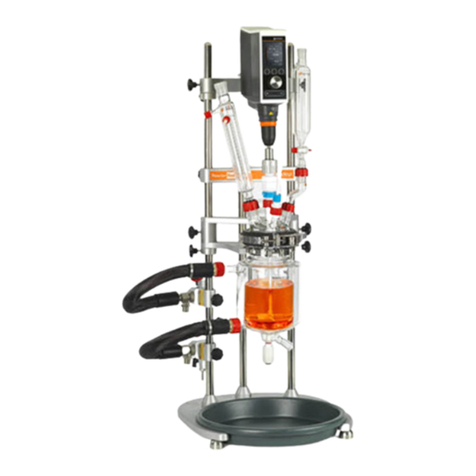
Radleys Reactor-Ready Lab Reactor User manual

accelerating chemistry
February 2023 | Issue 13
Reactor-Ready Lab Reactor
Including Reactor-Ready Filter Lab Reactor
Instructions

Contents
1 INTRODUCTION.............................................................................................................................................2
2 WARRANTY...................................................................................................................................................2
3 SAFETY GUIDE...............................................................................................................................................3
4 COMPONENT GUIDE .....................................................................................................................................4
4.1 REACTOR-READY CORE SYSTEM ............................................................................................................................4
4.2 REACTOR-READY FILTER CORE SYSTEM ...................................................................................................................5
5 REACTION AND FILTER VESSEL GUIDE ...........................................................................................................6
6 SET-UP AND OPERATION...............................................................................................................................7
6.1 SETTING UP REACTOR-READY...............................................................................................................................7
6.1.1 Requirements........................................................................................................................................7
6.1.2 Assembling the framework...................................................................................................................7
6.1.3 Assembling the filter support plate ......................................................................................................9
6.1.4 Assembling the manifolds and vessel support clamp .........................................................................10
6.1.5 Adding the T-beam support brace and stirrer support I-beam...........................................................12
6.1.6 Locating the vessel into the framework..............................................................................................13
6.1.7 Assembling the vessel lid, stirrer guide and stirrer shaft....................................................................16
6.1.8 Clamping the vessel lid and stirrer assembly to the vessel.................................................................17
6.1.9 Attaching the temperature probe to the vessel .................................................................................19
6.1.10 Attaching the quick-release insulated hoses to the vessel...............................................................20
6.1.11 Assembling the overhead stirrer.......................................................................................................21
6.2 SET-UP INSTRUCTIONS FOR FILTER VESSELS ONLY....................................................................................................24
6.2.1 Assembling the filter plate..................................................................................................................24
6.2.2 Attaching the filter plate clamp ..........................................................................................................27
6.2.3 Attaching a collection vessel...............................................................................................................29
6.3 CONVERTING REACTOR-READY CORE TO FILTER CORE .............................................................................................32
6.3.1 Dismantling the Reactor-Ready core system......................................................................................32
6.3.2 Assembling the Reactor-Ready filter core system ..............................................................................33
6.4 OPERATING REACTOR-READY ............................................................................................................................34
6.4.1 Optimising thermal performance .......................................................................................................34
6.4.2 Operating temperature range.............................................................................................................34
6.4.3 Choosing a thermoregulator (circulator) ............................................................................................35
6.4.4 Choosing a thermofluid.......................................................................................................................35
6.4.5 Choosing an overhead stirrer..............................................................................................................36
6.4.6 Connecting a thermoregulator to Reactor-Ready...............................................................................36
6.4.7 Charging Reactor-Ready with thermofluid .........................................................................................38
6.4.8 Draining thermofluid from Reactor-Ready .........................................................................................39
6.4.9 Disconnecting the thermoregulator ...................................................................................................40
6.4.10 Connecting the hose tidies................................................................................................................41
6.4.11 Static .................................................................................................................................................43
6.4.12 Filtration............................................................................................................................................44
7 JACKETED GLASS REACTION AND FILTER VESSELS .......................................................................................50
8 GENERAL SPECIFICATIONS...........................................................................................................................55
9 ROUTINE MAINTENANCE ............................................................................................................................59

2
1Introduction
Thank you for purchasing Reactor-Ready.
Please read this instruction manual thoroughly before operating the unit.
Reactor-Ready is a flexible benchtop reaction system with a single purpose-built framework that can
be used with a wide range of dedicated glass reaction and filter vessels and accessories. It can also
be attached to a thermoregulator to allow a fully comprehensive range of heating and cooling
operations to be performed.
Features
•Rapid vessel exchange, with quick-release vessel clamps and hose couplings.
•Dedicated standard and process glass reaction vessels, both single and double jacketed, ranging
in size from 100ml to 5L.
•Dedicated 1L and 2L single jacketed filter vessels.
•Triple support stand, with heavy-duty stainless steel support rods for maximum strength and
stability.
•Accepts all leading brands of overhead stirrer, allowing easy, tool-free adjustment.
•Self-aligning stirrer coupling that engages without the need for tools.
•Hose manifolds that allow easy thermofluid drain-down.
•Temperature range: -70°C to +230°C for reaction vessels (subject to thermoregulator).
•Temperature range: -30°C to +180°C for filter vessels (subject to thermoregulator).
•Wide range of glassware accessories, including condensers, dropping funnels, etc.
2Warranty
Reactor-Ready includes a one-year full parts and labour warranty from the date of the original
purchase.
Warranty will only be valid if a Warranty form is completed and returned within one month of the
date of purchase (see Warranty form at the back of this manual).
In the event of product failure, please contact your local distributor. Please do not return any goods
without prior agreement.

3
3Safety guide
Please read this safety guide completely before using Reactor-Ready.
•Reactor-Ready should only be operated by
trained and competent personnel. As with
all chemistries, a full risk assessment
should be performed prior to starting, and
care should be taken to monitor reactions
at all stages.
•It is the responsibility of the user to ensure
correct set up and continued maintenance
of the framework and clamps.
•Always ensure that the unit is located on a
level surface.
•Operate only in a fumehood with
protective safety sash.
•Always ensure the reaction or filter vessel
is clamped and supported correctly, using
the purpose-built framework and clamps.
The unit should never be operated without
this framework.
•Always read the complete instructions for
any third-party equipment, such as
overhead stirrers and thermoregulators, to
ensure you are not contravening any
safety recommendations or the
manufacturer’s warranty when used in
conjunction with Reactor-Ready.
•The maximum operating stirring speed for
the unit is 500rpm for continuous
operation and 800rpm for short periods.
•There is a risk of burns from hot or
extreme cold temperatures during and
after heating/cooling, so take care not to
touch the unit or any auxiliary equipment.
•Reactor-Ready will remain hot for a
considerable time after the heat source
has been turned off. A temperature probe
or temperature sensitive label can be used
to indicate when components are too hot
to touch.
•Before starting your operation, ensure all
fittings to the thermoregulator are fully
tightened with no leaks, and that the
manifold drain and vent valves are closed.
•Reactor-Ready metal components are
resistant to the majority of solvents and
are splash-resistant to dilute acids and
alkalis at room temperature.
•Wipe away chemical spills immediately
and avoid exposure to strong vapours such
as HCl, as continued exposure to chemical
vapours or liquids will cause corrosion to
metal and/or plastic components.
•Reactor-Ready can be used with reaction
vessels with a recirculating fluid at
temperatues between -70°C and +230°C,
or with filter vessels with a recirculating
fluid at temperatures between -30°C and
+180°C, without damage to the unit.
Careful inspection of all fluid connections
to the unit should be regularly performed
when operating at these temperatures.
•Ensure all wires and cables connecting
auxiliary equipment are secured such that
they cannot come into contact with the
unit surfaces or moving parts.
•Flowing liquids can create a build up of
static, leading to risk of sparks and
explosion. Care must be taken to properly
bond and ground components of Reactor-
Ready to meet local safety requirements.
•During operation, do not leave the unit
unattended unless in a supervised area.
5
4Component guide
4.1 Reactor-Ready core system
1
2
3
4
5
6
7
8
9
10
11
12
13
14
15
16
17
18
19
Aluminium base (with adjustable feet)
HDPE drip tray
Support rod bosses
Support rods –long (x2) and short (x1)
Lower supply manifold (with drain valve)*
Upper return manifold (with vent valve)
Safety stop collars (x4)
Vessel support clamp
T-beam support brace
Stirrer support I-beam (with sliding boss)
Quick-release insulated hoses
Rodaviss hose sealing caps
Vessel support collars
Glass lid (with sealing caps)
PTFE stirrer guide
Locking rod (for support rod bosses)
Stirrer drive coupling
O-ring seal and PTFE support collar
Hose tidies
* The lower supply manifold has been upgraded and now
features a more compact drain tap, as shown in Fig A.
2
8
1
9
6
5
11
12
13
14
15
18
16
17
4
10
19
Fig A
3
7

5
4.2 Reactor-Ready filter core system
1
2
3
4
5
6
7
8
9
10
11
12
13
14
15
16
17
18
19
20
21
Aluminium base (with adjustable feet)
HDPE drip tray
Support rod bosses (x3)
Extended support rods –long (x2) and short (x1)
Lower supply manifold (with drain valve)*
Upper return manifold (with vent valve)
Safety stop collars (x5)
Vessel support clamp
T-beam support brace
Stirrer support I-beam (with sliding boss)
Filter support plate
Quick-release insulated hoses
Rodaviss hose sealing caps
Vessel support collars
Glass lid (with sealing caps)
PTFE stirrer guide
Locking rod (for support rod bosses)
Filter plate clamp pin
Stirrer drive coupling
O-ring seal and PTFE support collar
Hose tidies
1
2
3
4
5
6
8
9
10
11
12
13
14
15
16
20
21
7
18
17
19
0
* See note on previous page about upgraded lower supply manifold.
7

6
5Reaction and filter vessel guide
For use with the Reactor-Ready core system
Reaction vessel kits
Process vessel kits
1
2
3
4
5
Glass reaction vessel with PTFE stopcock
PTFE anchor stirrer
Pt100 PTFE temperature probe
PTFE temperature probe adapter
Sidearm couplings (connecting cap and connecting
clip)
1
2
3
4
5
Glass process reaction vessel with PTFE stopcock
PTFE turbine stirrer
Pt100 PTFE temperature probe
PTFE temperature probe adapter
Sidearm couplings (connecting cap and connecting
clip)
For use with the Reactor-Ready filter core system
Filter vessel kits
Filter Plate assembly
1
2
3
4
5
Glass filter vessel
PTFE turbine stirrer
Pt100 PTFE temperature probe
PTFE temperature probe adapter
Sidearm couplings (connecting cap and connecting
clip)
1
2
3
4
5
6
7
Filter plate (PTFE or PEEK available)
Aluminium filter cup
Sintered glass membrane support
Filter Membrane Evaluation Kit (see page 45)
BOV glass body and piston
O-ring
Gasket
1
2
3
5
4
1
1
2
2
5
3
3
4
7
6
4
5
2
1
4
3
5

7
6Set-up and operation
6.1 Setting up Reactor-Ready
6.1.1 Requirements
•Access to two mains power sockets –one for the thermoregulator and one for the overhead stirrer.
•Access to additional mains power sockets if pumps or vacuum pumps are required.
•A clear unobstructed site on a level surface within your fumehood.
•Cooling water supply for the reflux condenser.
•Inert gas and vacuum supply for operating under an inert atmosphere.
•An adjustable wrench for tightening the quick-release insulated hoses and thermofluid hoses.
formation
6.1.2 Assembling the framework
Important information
→Before you begin assembly, ensure that the framework is placed in its final position, as once fully
assembled the unit should not be moved.
→Make sure there is room for connections to the thermoregulator, and that all thermofluid hoses
can be positioned and supported safely.
Step 1
Position the aluminium base on a flat work
surface within your fumehood, ensuring that it is
level and stable.
All five of the adjustable feet should be in contact
with the work surface.
If necessary, you can adjust the height of each
individual foot by screwing it in or out.
Locate the drip tray into the base.

8
Step 2
Screw the three support rods into the base.
The shortest rod should be positioned in the centre,
and the two longer rods on either side.
Do not tighten the support rod bosses (locking
knobs) at this stage.
Note: Filter vessels require extended support rods,
so ensure you are using the correct support rods for
your application.
Important information
→Once the support rods have been connected to the base, wipe them with the lubricating cloth
supplied to aid further assembly and operation of components.
Step 3
Lower the T-beam support brace onto the
support rods.
Slide the support brace down the support rods
until it is resting on the support rod bosses.
Now fully tighten the support rod bosses using
the locking rod (supplied).
Remove the T-beam support brace from the
framework.
Useful notes
❖The T-beam support brace ensures that the support rods are correctly screwed into position, and
that they are straight and parallel.
❖The support brace should slide freely up and down the support rods. To enable this, apply gentle
pressure to the centre of the brace when raising or lowering it. This will help to keep the brace
level and prevent it from twisting (which may cause it to stick).

9
Step 4
If using a filter vessel, the filter support plate must be connected to
the framework at this point.
Note: If a filter vessel is not being used, go straight to Section 6.1.4
–Assembling the manifolds and vessel support clamp (see page 10).
6.1.3 Assembling the filter support plate
Step 1
To connect the filter support plate to the
framework, first place a safety stop collar onto the
right-hand support rod and slide it down until it
almost reaches the bottom of the support rod.
Hand-tighten the locking knob to secure.
Step 2
With the ridged side uppermost, lower the filter
support plate onto the right-hand support rod
and slide it down until it rests on top of the safety
stop collar.
Hand-tighten the two outer locking knobs to secure
the support plate in place.
Note: If necessary, the position of the support plate
and safety stop collar can be adjusted later, when
all the components are in place.
Useful notes
❖The filter support plate is positioned towards the lower end of the support rod to allow enough
space above it for additional components, such as the filter plate, filter vessel and overhead
stirrer. It can be located on either of the side support rods, but it is recommended that the right-
hand rod is used, as this allows the most ergonomic alignment of hoses, vessels and other system
components.
❖The safety stop collar limits the downward movement of the filter support plate.

10
6.1.4 Assembling the manifolds and vessel support clamp
Useful notes
❖Reactor-Ready features independent supply and return manifolds to simplify the connection
between the thermoregulator and reaction or filter vessel. The manifolds are attached to the
support rods and feature precision bore slide bearings. These allow for smooth and independent
vertical and horizontal adjustment, providing the flexibility to accommodate different vessel sizes.
❖The lower supply and upper return manifolds
can be located on either of the side support rods,
but it is recommended that the left-hand rod is used,
as this allows the most ergonomic alignment of
hoses, vessels and other system components.
Step 1
With the drain valve pointing downwards, slide
the lower supply manifold onto the left-hand
support rod. Ensure there is enough space below
the manifold to allow the thermoregulator hose to
be attached.
When the manifold is in the correct position,
hand-tighten the locking knob.
Note: The lower supply manifold has been
upgraded and now features a more compact
drain tap, as shown in Fig A on page 4.
Step 2
With the vent valve pointing upwards, slide the
upper return manifold onto the left-hand support
rod, above the lower supply manifold. Ensure there
is enough space below the manifold to allow the
thermoregulator hose to be attached.
When the manifold is in the correct position,
hand-tighten the locking knob.

11
Important information
→The drain valve on the lower supply manifold must be pointing downwards to allow complete
drainage of the vessel.
→The vent valve on the upper return manifold must be pointing upwards to avoid leakage of
thermofluid during drainage of the vessel.
Step 3
Slide a safety stop collar onto each of the outer
support rods. These will support the vessel
support clamp, which will be positioned above
the manifolds.
When the safety stop collars are in approximately
the correct position, hand-tighten the locking
knobs.
Step 4
Now lower the vessel support clamp onto
the outer support rods and slide it down until it
is in approximately the correct position. Secure it in
place by hand-tightening the two locking knobs.
Adjust the safety stop collars so they are located
directly under the vessel support clamp and
retighten the locking knobs.
Useful notes
❖In some circumstances, it may be preferable to locate the vessel support clamp between the
lower supply and upper return manifolds, rather than above them, to give optimal spatial
alignment of system components.
❖The safety stop collars limit the downward movement of the vessel support clamp.

12
6.1.5 Adding the T-beam support brace and stirrer support I-beam
Step 1
Lower the T-beam support brace onto all three
support rods. The rounded top of the central
support rod should be just visible above the central
hole in the brace.
Hand-tighten the three locking knobs.
Useful notes
❖The T-beam support brace’s sole function is to add stability to and maintain alignment of the
framework.
Step 2
Slide a safety stop collar onto each of the outer
support rods. These will support the stirrer support
I-beam.
When they are in approximately the correct
position, hand-tighten both locking knobs.
Step 3
Now slide the stirrer support I-beam onto
the outer support rods, ensuring the two knobs on
the central sliding boss are pointing upwards and to
the front. Once it is in the correct position, secure it
by hand-tightening the two outer locking knobs.
Adjust the safety stop collars so that they are
located directly under the I-beam and retighten the
locking knobs.
Useful notes
❖The stirrer support I-beam is designed to support an overhead stirrer, and features precision bore
slide bearings enabling smooth height adjustment, offering maximum user flexibility in
configuring the system.

13
Reactor-Ready core system
Assembled frame
Reactor-Ready filter core system
Assembled frame
6.1.6 Locating the vessel into the framework
Warning!
Only Radleys vessels should be used with Reactor-Ready as they have been specifically
engineered to ensure a safe fit and leak-tight seal. Never use vessels from other manufacturers.
For further information about Radleys vessels, see Section 7 on page 50.
A vessel support collar must first be attached to your vessel before locating it into the vessel support
clamp on the framework.

14
Step 1
Select the appropriate vessel for the chemistry you
are peforming. Invert the vessel and place it on a
flat surface, ensuring the sidearms are pointing to
the right.
Undo the bolt on the vessel support collar and
place the collar around the neck of the vessel.
Note: The opening of the vessel support collar
should be facing the front and central (it should be
at 90° to the vessel sidearms). Partially tighten the
bolt so that the collar is closed but still free to move
up and down the vessel neck.
Step 2
Adjust the position of the vessel support collar so
that the distance from the bottom of the vessel
neck (with vessel inverted) to the top of the
protruding lugs on the vessel support collar is
between 40 and 41mm.
Use the orange alignment jig (supplied), or a ruler if
the jig is not available, to ensure the collar is
correctly positioned.
Once in the correct position, fully tighten the
fastening bolt on the vessel support collar.
Step 3
Turn the vessel the correct way up and slightly tilt it
away from you. Slot the lug on the back of the
vessel support collar into the central recess on the
vessel support clamp.
Straighten the vessel, locating the lugs on each side
of the vessel support collar into the rectangular
recesses on each side of the vessel support clamp.
The vessel is now fully supported.
Note: When the vessel is supported by the vessel
support clamp, some movement of the vessel is still
possible until the clamp is fully closed.

15
Important information
→The vessel support collar must be positioned correctly to ensure smooth operation of the vessel
support clamp. If after assembling the support collar the vessel is not vertically aligned when
located in the clamp, it may be possible to loosen the fastening bolt on the vessel support collar
and realign the vessel whilst it is located in the clamp. Once correctly aligned, the fastening bolt
on the collar must be retightened.
→Alternatively, remove the vessel and refit the vessel collar (as described earlier), ensuring the
distance from the bottom of the vessel neck to the top of the protruding lugs on the collar is
between 40 and 41mm. (Use the alignment jig or a ruler to ensure this is the case.)
Step 4
For units manufactured before mid 2010 only
Units manufactured before mid 2010 feature two
extra locking knobs on either side of the clamp.
To further secure the vessel, hand-tighten these
locking knobs until they lightly grip the side lugs on
the vessel support collar.
Note: The locking knobs must be loosened before
the final clamping operation is performed, as the
vessel must be free to move as it is being clamped.
Important information
→It is advisable to make any adjustments to the height of the vessel on the framework at this stage
by loosening the locking knobs on the support clamp and sliding it up or down. Subsequent
adjustments to the height of the manifolds and stirrer support may also be necessary.
→If using a filter vessel, ensure there is enough space below the vessel to allow the BOV piston to
be fully opened, and the filter plate assembly to be lowered sufficiently to enable the filter cake
to be fully withdrawn from the filter vessel body.

16
6.1.7 Assembling the vessel lid, stirrer guide and stirrer shaft
Step 1
Before attaching the glass lid to the vessel,
insert the PTFE stirrer guide into the central B24
port on the lid.
Hand-tighten the red Rodaviss screw cap to secure
the stirrer guide in place.
Step 2
Loosen the metal locking cap on top of the PTFE
stirrer guide (but do not unscrew fully).
Feed the stirrer shaft up through the underside of
the vessel lid and into the stirrer guide. Continue to
slide the stirrer shaft up until it just protrudes
above the metal locking cap.
Hand-tighten the metal locking cap to secure the
stirrer shaft in place.
Important information
→The stirrer assembly (stirrer guide + stirrer shaft) must be securely connected to the vessel lid
before the lid is placed on the vessel.

17
6.1.8 Clamping the vessel lid and stirrer assembly to the vessel
Step 1
Assemble the vessel O-ring seal and PTFE O-ring
support collar.
Place the assembly onto the flange of the vessel
neck ensuring that the retaining lip of the O-ring
assembly is located in the neck of the vessel.
Step 2
Take the lid and stirrer assembly and guide the
stirrer shaft through the neck of the vessel.
Then lower the lid onto the vessel O-ring, ensuring
that the lid flange, O-ring and vessel flange are all
aligned and sitting flush, and that the ports are in
the correct position.
Useful notes
❖Once you have placed the lid and stirrer assembly on the vessel flange, check that the stirrer shaft
is in the optimal position for your application. To reposition it, you will need to remove the lid and
stirrer assembly, loosen the locking cap on the stirrer guide and slide the stirrer shaft up or down
as required. Once in the correct position, retighten the locking cap on the stirrer guide.
Step 3
You will now need to clamp the lid and vessel
together using the vessel support clamp.
To do this, gently close the jaws of the vessel
support clamp around the join where the vessel lid
flange and the vessel flange meet.

18
Step 4
Lock the clamp in place with the fastening clip.
This is done by hooking the bolt of the fastening
clip into the retaining recess of the clamp and then
snapping the clip shut.
Visual inspection of the O-ring through the opening
at the front of the clamp should indicate a witness
line where it seals against the lid flange.
Important information
→There should be minimal movement of the vessel and lid when clamping them together. If
signifcant movement is observed (either sideways or vertically), it is likely that the vessel support
collar is incorrectly positioned on the vessel neck. You will need to remove the vessel from the
vessel support clamp and reposition the vessel support collar.
See Section 6.1.6 on page 13 –Locating the vessel into the framework, for reference.
Useful notes
❖The vessel support clamp can be adjusted by screwing the
bolt on the fastening clip in or out to tighten or loosen
the grip. This is best done when the clamp is open.
Warning!
Never use too much force when locking the vessel support clamp as this may damage the vessel.

19
6.1.9 Attaching the temperature probe to the vessel
Step 1
Insert the PTFE temperature probe adapter into the
B19 port on the glass lid.
Hand-tighten the red Rodaviss screw cap to secure
the adapter in place.
Partially unscrew the blue locking cap on the top of
the probe adapter.
Step 2
Feed the Pt100 temperature probe through the top
of the blue locking cap on the probe adapter until it
exits the other end.
Keep feeding the probe through until it is the
desired length. The temperature probe can be
gently bent to ensure that it does not obstruct the
stirrer shaft inside the vessel.
Hand-tighten the blue locking cap to secure the
temperature probe in place.
Useful notes
❖A Pt100 temperature probe is supplied with vessel kits or can be purchased as a separate item
Step 3
Attach any additional components required (e.g.
dropping funnels, solids addition funnels, etc.) to
the remaining ports on the glass lid, and secure by
hand-tightening the red Rodaviss screw caps.
Note: Any ports on the glass lid that are not in use
should be sealed off with a red Rodaviss sealing cap
(supplied x4). These sealing caps have PTFE faced
liners for an inert seal.
Table of contents
Other Radleys Laboratory Equipment manuals

Radleys
Radleys Carousel 6 Plus User manual

Radleys
Radleys Reactor-Ready User manual

Radleys
Radleys Carousel Standard User manual

Radleys
Radleys GreenHouse Plus User manual

Radleys
Radleys Heat-On RR68000 User manual

Radleys
Radleys Carousel 12 Plus User manual

Radleys
Radleys Reactor-Ready User manual

Radleys
Radleys Reactor-Ready Pilot User manual

Radleys
Radleys GreenHouse User manual

Radleys
Radleys Carousel 6 Plus User manual