OWL Dual OWL Series User manual

Operations Guide
Dual OWL Series Multimode Light
Sources
Optical Wavelength Laboratories (OWL)
N9623 Old Hwy 12
Whitewater, WI 53190
Phone: 262-473-0643
Internet: OWL-INC.COM
Date: March 21, 2019
Version 3.0
Dual OWL Series
Operations Guide
Multimode Light Sources
Optical Wavelength Laboratories

CONTENTS
1.0 GENERAL
2.0 FUNCTIONAL DESCRIPTIONS
3.0 APPLICATIONS
3.1 PRECAUTIONS
3.1.1 Safety
3.1.2 Operational
3.1.3 Connector
3.2 REQUIRED ACCESSORIES
3.2.1 Cleaning Supplies
3.2.2 Patch Cords
3.2.3 Optical Fiber Adapters
3.3 TYPICAL APPLICATIONS
4.0 MAINTENANCE / CALIBRATION
5.0 WARRANTY
6.0 SPECIFICATIONS
FIGURES
Figure 1 - Dual OWL Multimode Light Source
PAGE
2
2
3
3
3
3
3
3
3
3
3
3
4
4
4
2

1.0 GENERAL
Thank you for your purchase of an Optical Wavelength Labs (OWL) Dual OWL series multimode light source.
Dual OWL series light sources are LED-based light sources designed to test multimode fiber optic links.
The LED indicators show whether the unit is ON or OFF, and whether the battery has enough
power to maintain its calibrated output power. Dual OWL series light sources contain stabilized 850 and/or
1300nm LEDs that conforms to international testing standards, and single-wave versions may include a VFL.
Each Dual OWL series light source comes with a protective rubber boot, CD-ROM based operations manual,
and USB battery charger and cable.
Typical uses include telecommunications networks, data networks, cable television, and industrial equipment
control.
The source is simple to operate with two buttons: one for controlling power and one for selecting the output
port. LED indicators highlight the selected port and verify that battery power is sufficient to maintain the
calibrated output power, and wavelength is indicated by 7-segment LED display.
The
LED outputs are temperature compensated and are calibrated to couple -20dBm of optical power into
multimode fiber.
- 2 -
Figure 1 - Dual OWL
Multimode Light Source
2.0 FUNCTIONAL DESCRIPTIONS
1. PortA- Houses either 850nm or 650nm VFL.
2. USB Charger Port - Allows for charging internal Lithium
Polymer battery.
3. Port B - either 1300nm or 650nm VFL.
4. Port A Indicator LED - Indicates the ON/OFF status of the
source installed in PortA.
5. Port B Indicator LED - Indicates the ON/OFF status of the
source installed in Port B (if installed).
6. Charger Indicator LED - Indicates the status of the charger
port.
7. Power Button - Powers the unit ON or OFF.
8. Port Select Button - Switches the unit between Port A and
Port B.
NOTE: During normal operation, if the indicator LEDs are not lit,
this indicates that the battery has insufficient power to provide
accurate readings and must be recharged.
NOTE: Single wavelength versions (850nm only or 1300nm only)
will only have a single optical port.
13
2
4 5
6
78
Model Port A Port B
DO2-85
DO2-85V
DO2-13
DO2-13V
DO2
850nm
850nm
1300nm
1300nm
850nm
–
650nm VFL
–
650nm VFL
1300nm

- 3 -
3.0 APPLICATIONS
3.1 PRECAUTIONS
3.1.1 Safety - Caution must be exercised when working with optical equipment. Most transmission
equipment and light sources use light that is invisible to the human eye. High energy light is potentially
dangerous, and can cause serious, irreparable damage to the eye. Thus, it is recommended to look
into the connector port of a light source or the end of a fiber.
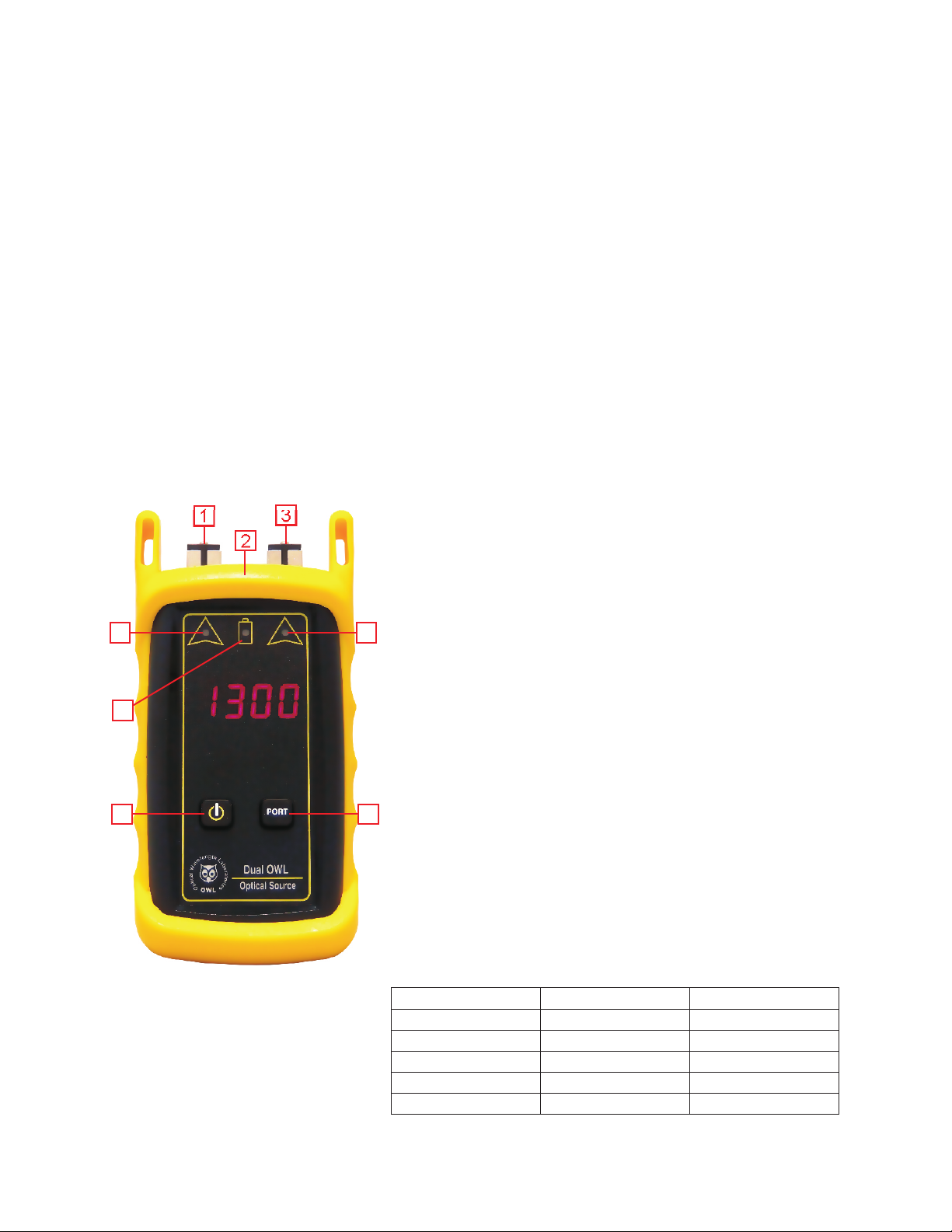
3.1.2 Operational - In order to ensure accurate and reliable readings, it is vitally important to clean ferrules
containing optical fibers and optical connector ports. If dirt, dust, and oil is allowed to build up inside
connector ports, this may scratch the surface of the LED diode, producing erroneous results. Replace dust
caps after each use.
3.1.3 Connector - Do NOT insert APC (Angled Physical Contact) connectors into the optical ports on the
Dual OWL as this may damage the light source inside the port.
3.2 REQUIRED ACCESSORIES
3.2.1 Cleaning Supplies - It is recommended to clean fiber ferrules before each insertion with 99% or better
isopropyl alcohol and a lint free cloth, or a special in-adapter ferrule cleaner. A can of compressed air should
be available to dry off the connector after wiping, and to blow out dust from bulkheads.
3.2.2 Patch Cords - Patch cords may be needed to connect the Dual OWL series light source to the system
under test. The connector styles on the patch cord must match the type on the light source and the type of the
system under test.
3.2.3 Optical Fiber Adapters - Optical fiber adapters are used to connect two connectorized fibers together,
and may be necessary to adapt your patch cords to the system under test.
3.3 TYPICALAPPLICATIONS
Dual OWL series multimode light sources can be used as diagnostic and measurement tools of optical
transmission systems and fiber optic links. These applications can be found in several industries, including
premise, LAN, CATV, and Telco.
Dual OWL series multimode light sources are designed to emit a temperature-stabilized source of light to be
used for optical loss measurement. The optical power emitted by the light source serves as an optical
reference, which is otherwise known as the “zero” point when a power meter is “zeroed”. Optical loss
measurements are useful for measuring the attenuation, or loss, of a fiber link. The loss value can then be
compared to a pre-calculated link budget, which is used to determine if the fiber link will operate within the
parameters of the transmission equipment.
The formula for calculating loss in a fiber link is: L = P - P
a r
where Lis the amount of optical loss in dB, Pis the absolute power in dbm, and Pis the reference power in
a r
dBm.
Optical loss measurements can also be used for fiber optic link certification. Link certification is a process
where optical loss measurements are compared to a link budget calculated using fiber optic cabling
standards.
NEVER

- 4 -
4.0 MAINTENANCE / CALIBRATION
4.0.1 Repair of this unit by unauthorized personnel is prohibited, and will void any warranty associated with
the unit.
4.0.2 For accurate readings, the optical connectors on Dual OWL series light sources and the connectors
on the patch cords should be cleaned prior to attaching them to each other. Minimize dust and dirt buildup by
replacing the dust caps after each use.
4.0.3 It is recommended to have Optical Wavelength Laboratories calibrate Dual OWL series light sources
once per year.
5.0 WARRANTY
5.0.1 Optical Wavelength Labs products have a two-year factory warranty, which covers manufacturer
defect and workmanship only, valid from the date of shipment to the original customer.
5.0.2 Products found to be defective within the warranty will be either repaired or replaced, at the option of
Optical Wavelength Labs.
5.0.3 This warranty does not apply to units that have been repaired or altered by anyone other than Optical
Wavelength Labs, or have been subjected to misuse, negligence, or accident.
5.0.4 In no way will Optical Wavelength Labs liabilities exceed the original purchase price of the unit.
5.0.5 To return equipment under warranty, please contact Optical Wavelength Labs for a RMA number. To
ensure quick turnaround, please include a short description of the problem and a phone number where you
can be reached during normal business hours.
Optical Wavelength Labs
N9623 Old Highway 12
Whitewater, WI 53190
Internet: owl-inc.com
Phone: 262-473-0643
Fax: 262-473-8737
6.0 SPECIFICATIONS
Conforms to the Harmonized European Standards EN 61326-1 and EN 61010-1.
Launch Method LED
Connector SC
Center Wavelength (850nm) 850 ±20nm
Center Wavelength (1300nm) 1290nm min
1350nm max
Spectral Width (FWHM; 850 nm) 35 nm
Spectral Width(FWHM; 1300nm) 170nm
Output Power -20.0 dBm
Initial Accuracy 0.1 dB
Fiber Type multimode
Battery Life up to 120 hrs (Lithium Polymer)
Battery Capacity Display Yes
Operating Temperature 0 to 55° C
Storage Temperature 0 to 75° C
Dimensions 2.75” x 4.94” x 1.28”
Weight 154g
Optional VFL Specifications
Wavelength 650nm Laser
Output Power 1 mW (0 dBm)
Operating Modes CW, Modulated
Connector SC
This manual suits for next models
5
Table of contents
Other OWL Laboratory Equipment manuals
Popular Laboratory Equipment manuals by other brands

REITEL
REITEL STEAMY MINI operating instructions

Agilent Technologies
Agilent Technologies 7694 manual

Consort
Consort EVS1000 Series manual

Becton Dickinson
Becton Dickinson CLAY ADAMS CA6000 user manual

Excillum
Excillum MetalJet D2+ operating manual

Haemonetics
Haemonetics MCS+ Operator and maintenance manual