2 3
1Emulation Driver Installation
Skip this step if you are using Code Composer v4 or later, and it is already
installed on your system
The USB510W Emulator shipped with its emulation drivers on CD ROM media
that are needed by Windows and Code Composer Studio v3.3 for operation.
2Hardware Installation
1. Insert the Emulation Driver CDROM into your PC’s CDROM drive.
2. Follow the installation wizard, and when done, you can install the emulator hardware.
If the installation executable fails to start automatically, run X:\Setup\Setup.exe,
where [X] is the drive letter for your CD ROM drive.
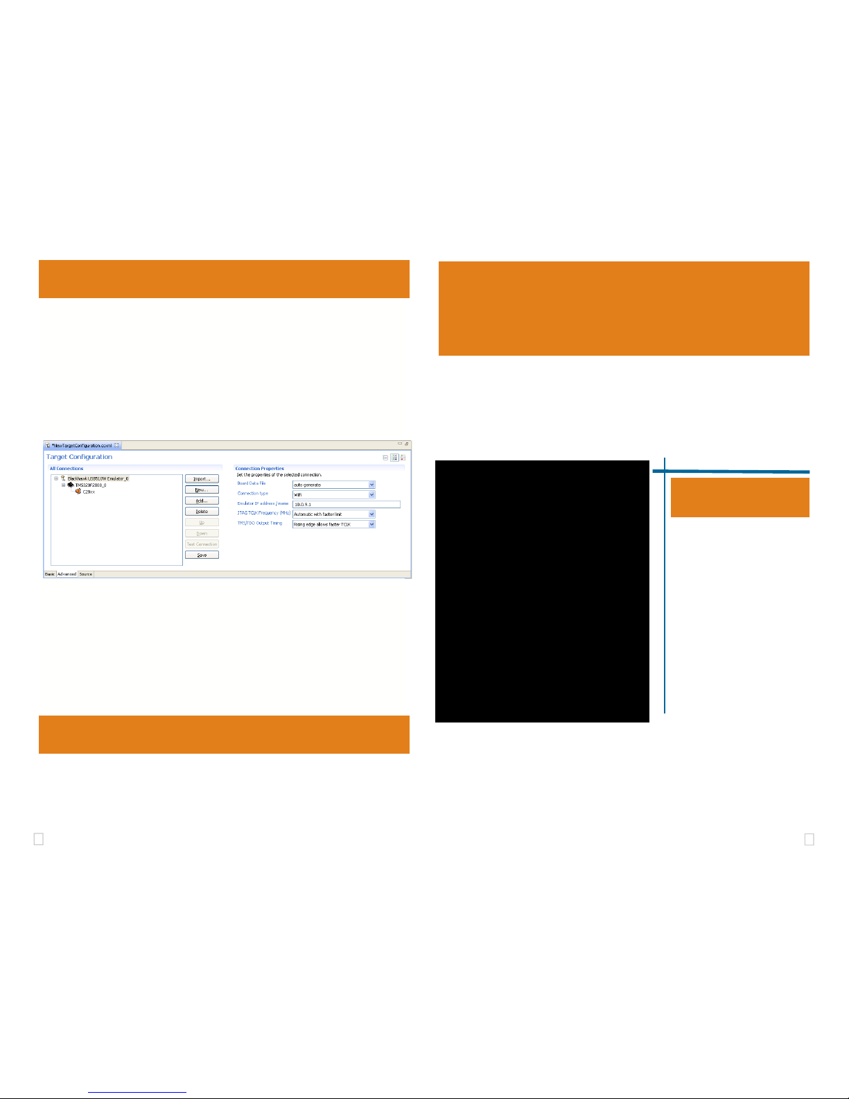
Network Cofiguration 4
1. Place the USB510W module in desired location and connect the 5v USB mini B plug of the
power supply to the 5-volt DC input on the USB510W (see figure 1).
2. Attach the emulator’s JTAG cable assembly (the 20-pin, 2x10 JTAG connector shown in
figure 2) to the pin converter with corresponding header on the target board. Make sure the
target board is not powered when connecting!
If the USB510W is already installed on your network and connected to a target board,
you can skip this section and move to section 3.
WARNING
Be careful to connect interface cables with the correct orientation. Pin 1 on the inter-
face cable should match Pin 1 on the DSP system connector. The JTAG cable as-
sembly features a "keyed" connector to minimize the chance of error.
Make sure the target is not powered when connecting!
3Ad-Hoc Create Mode Setup
The default WiFI setup for the USB510W is “Ad-Hoc Create”. This will allow a com-
puter to join to the USB510W network.
1. From your windows Start button, choose , choose: Start > Settings > Control
Panel > Open Windows Network connections
2. Right Click on the Wireless Network Connection, and choose properties, which will
display the network properties dialog.
3. Highlight “Internet Protocol (TCP\IP)” entry and click the properties button
4. In the dialog, configure the settings to IP 10.0.9.2, Subnet Mask 255.255.255.0
You should record your current settings to return them back to their original settings later.
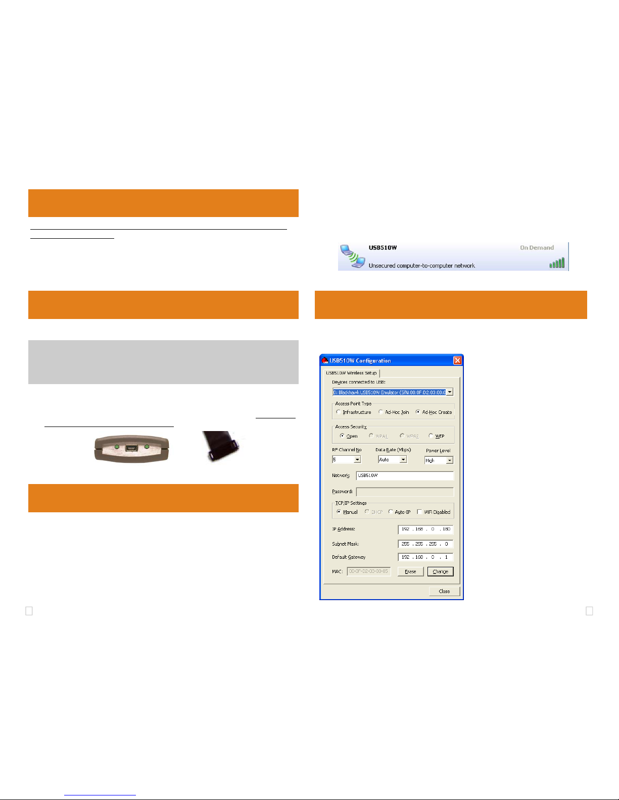
• This section describes how to customize the USB510W configuration
• Launch the USB510W Configuration utility from windows desktop shortcut
FIGURE 4—USB510W Configuration Utility
FIGURE 2— 20-pin JTAG EndFIGURE 1— WLAN,USB &
Power Endplate
5. Using the Windows wireless network connection, you can search for available Wireless Net-
works. You should see the USB510W-<serial> SSID as shown in figure 3.
6. Select the entry and choose connect. If you see Acquiring network address for more
than few seconds, go back check you’re IP settings for the USB510W and your PC’s wire-
less adapter TCP/IP settings.
FIGURE 3—USB510W AD-HOC SSID
• Select your USB510W to be con-
figured from the drop down menu
• Choose the Access Point Type you
wish to use with the USB510W
• Select the Access Security Type you
wish to use with your USB510W or is
configured on your network
• Optional—Set the RF channel Num-
ber, The USB510W WiFi Data Rate,
and the USB510W WiFi antenna
Power level
• Type in the SSID for the Emulator to
be connected too if you chose Infra-
structure/Ad-Hoc Join modes, or the
SSID the emulator will broadcast if you
chose Ad-Hoc Create Mode.
• Type in the Password for your network
if a Access Security option is not open.
• Setup the IP setting the emulator will
use that bet matches your network, for
Ad-Hoc mode it is recommended to
use Manual static IP settings.