BLACKIRON BI-HE115V-1500 User manual

MANUALE DI USO E MANUTENZIONE
USE AND MAINTENANCE MANUAL
BLACKIRON Italy
Via E. Rizzi 9/11 - 20077 Melegnano (MI)
Tel. +39 0239432304 - Fax +39 0287152020
Cod. 7.020.0735-B Ed. 05/2019
CENTRALINA ELETTRICA PER
TENSIONATORI IDRAULICI
ELECTRIC BOLT TENSIONERS
UNIT
D
E
F
C
1
2
3
B
A
3
2
1
5
C
D
4
6
7
8
A
B
E
5
4
DMR DATE
REVISION
DRAWING MODIFICATION HISTORY
BLACKIRON - ALL RIGHT RESERVED
- - -
THIS DRAWING IS CONFIDENTIAL. IT IS THE SOLE AND EXCLUSIVE
PROPERTY OF BLACKIRON AND IS SUBJECT TO RETURN UPON
REQUEST. IT MAY NOT BE COPIED, DUPLICATED, DISCLOSED ,
TRANSMITTED OR COMMUNICATED TO A THIRD PARTY IN ANY
MANNER, IN WHOLE OR ANY PART THEREOF, WITHOUT THE PRIOR
WRITTEN CONSENT OF THE OWNER; NOR MAY IT BE USED FOR ANY
PURPOSES OTHER THAN IN RELATION TO THE SINGLE CIRCUMSTANCE
IN CONNECTION WITH WHICH IT HAS BEEN SUPPLIED. FOR
COPYRIGHT PURPOSES THIS IS DEEMED TO APPLY EQUALLY TO THE
DOCUMENT AND TO ANY DESIGNS, CALCULATIONS, RESULTS OR
OTHER CONCEPTUAL MATTER DEPICTED THEREIN
UNLESS OTHERWISE STATED:
ALL DIMENSIONS IN MILLIMETERS
ALL UNSTATED CHAMFERS 1X45
SURFACE FINISH 3.2
REMOVE SHARP EDGES
IF IN DOUBT ASK
DO NOT SCALE DRAWING
29-04-2019
.
AB
MM
DIMENSIONS WITHOUT TOLERANCES
MEDIUM PRECISION - ISO2768
UNI EN22768
MATERIAL
CHECKED BY
DATE
SCALE
29-04-2019
29
BI-HE230V-1500 - 1500
bar electric unit
7.048.1156-2
DRAWN BY
1:3.5
DRAWING TITLE
SUP. TREAT.
DRAWING No.
DATE
WEIGHT (kg)
HEAT TREAT.
BI-HE -1500
115V
230V
380V

IMPORTANTI INFORMAZIONI SULLA SICUREZZA
LEGGERE QUESTO MANUALE PRIMA DI OGNI OPERAZIONE
E’ RESPONSABILITA’ DEL DATORE DI LAVORO FORNIRE IL
PRESENTE MANUALE ALL’OPERATORE
L’INOSSERVANZA DELLE AVVERTENZA POTREBBE CAUSARE
DANNI E LESIONI
SALVARE QUESTE ISTRUZIONI. NON DISTRUGGERE.
IMPORTANTE - LEGGERE ATTENTAMENTE
Questo manuale contiene informazioni importanti per la corretta instal-
lazione, il funzionamento e la manutenzione di questa apparecchiatura.
Tutte le persone coinvolte nell’installazione, il funzionamento e la ma-
nutenzione di questa apparecchiatura devono essere perfettamente
a conoscenza del contenuto di questo manuale. Per la salvaguardia
contro la possibilità di lesioni personali o danni alla proprietà, seguire
i consigli e le istruzioni di questo manuale. Conservare il manuale per
riferimento.
L’esploso delle parti di ricambio di questo prodotto chiamando il nostro
ufcio Assistenza.
IMPORTANT SAFETY INFORMATION ENCLOSED.
READ THIS MANUAL BEFORE OPERATION.
IT IS THE RESPONSIBLITIY OF THE EMPLOYER TO PLACE
THE INFORMATION IN THIS MANUAL INTO THE HANDS OF THE
OPERATOR.
FAILURE TO OBSERVE THE FOLLOWING WARNINGS COULD
RESULT IN INJURY.
SAVE THESE INSTRUCTIONS. DO NOT DESTROY.
IMPORTANT - READ CAREFULLY
This manual contains important information for the correct installation,
operation and maintenance of this equipment. All persons involved in
the installation, operation and maintenance of this equipment must
be thoroughly familiar with the contents of this manual. To safeguard
against the possibility of personal injury or property damage, follow the
recommendations and instructions of this manual. Keep this manual
for reference.
Repair parts sheets for this product are available by calling our Service
department.

Cod. 7.020.0735-B - Rev. 05/2019
1.0 - ISTRUZIONI AL RICEVIMENTO
2.0 - NORME SULLA SICUREZZA
3.0 - SPECIFICHE TECNICHE
3.1 - CARATTERISTICHE TECNICHE
3.2 - DIAGRAMMA PORTATE
3.3 - SCHEMA IDRAULICO
4.0 - INSTALLAZIONE
4.1 - TAPPO DI CARICO OLIO CON SFIATO SUL SERBATOIO
4.2 - DIMENSIONI CENTRALINA
4.3 - COLLEGAMENTI ELETTRICI
4.4 - LIVELLO OLIO
4.5 - COLLEGAMENTO IDRAULICO DEI TUBI FLESSIBILI
5.0 - FUNZIONAMENTO
5.1 - INTERRUTTORE ON-OFF SUL QUADRO ELETTRICO
5.2 - FUNZIONAMENTO DEL TELECOMANDO
5.3 - FUNZIONAMENTO DELLA CENTRALINA
5.4 - REGOLAZIONE DELLA PRESSIONE
6.0 - MANUTENZIONE
6.1 - CONTROLLO DEL LIVELLO OLIO
6.2 - CAMBIO DELL’OLIO E PULIZIA DEL SERBATOIO
6.3 - OLIO IDRAULICO
7.0 - GARANZIA
8.0 - ELIMINAZIONE DEI DIFETTI
8.1 - GUIDA PER L’ELIMINAZIONE DEI DIFETTI
1.0 - RECEIVING INSTRUCTIONS
2.0 - SAFETY ISSUES
3.0 - SPECIFICATIONS
3.1 - TECHNICAL DATA
3.2 - FLOW CHART
3.3 - HYDRAULIC DIAGRAM
4.0 - INSTALLATION
4.1 - RESERVOIR OIL FILL PLUG WITH BREATHER HOLE
4.2 - Unit DIMENSIONS
4.3 - ELECTRICAL CONNECTIONS
4.4 - OIL LEVEL
4.5 - HYDRAULIC HOSES CONNECTIONS
5.0 - OPERATION
5.1 - Unit ON-OFF SWITCH
5.2 - REMOTE CONTROL OPERATION
5.3 - Unit OPERATION
5.4 - PRESSURE SETTING
6.0 - MAINTENANCE
6.1 - CHECK OIL LEVEL
6.2 - CHANGE OIL AND CLEAN RESERVOIR
6.3 - HYDRAULIC OIL
7.0 - WARRANTY
8.0 - TROUBLESHOOTING
8.1 - TROUBLESHOOTING GUIDE
4 / 5
4 / 13
12 / 13
12 / 13
12 / 13
12 / 13
12 / 13
14 / 15
14 /15
14 / 15
16 / 17
16 / 17
18 / 19
18 / 19
18 / 19
20 / 23
22 / 25
24 / 25
26 / 27
26 / 29
28 / 29
28 / 31
30 / 31
32 / 37
SOMMARIO INDEX
pag. 3

Cod. 7.020.0735-B - Rev. 05/2019 pag. 4

Cod. 7.020.0735-B - Rev. 05/2019
Controllare visivamente tutti i componenti per accertare eventuali danni
derivanti dal trasporto. Se del caso, sporgere subito reclamo al trasporta-
tore. I danni causati durante il trasporto non sono coperti dalla garanzia.
Il trasportatore è responsabile degli stessi e deve rispondere di tutte le
spese e costi per la rimessa in efcienza del materiale.
SICUREZZA ANZITUTTO
ISTRUZIONI AL RICEVIMENTO RECEIVING INSTRUCTIONS
1.0
NORME SULLA SICUREZZA SAFETY ISSUES
2.0
Leggere attentamente tutte le istruzioni, le Precauzioni ed Avvertenze
che si devono osservare durante l’impiego delle attrezzature. Rispettare
tutte le norme di sicurezza per evitare infortuni alle persone e danni alle
cose. Il Costruttore non è responsabile per infortuni e danni causati dal
mancato rispetto delle Norme di Sicurezza, dall’uso e dall’applicazione
impropria del prodotto o dalla sua mancata manutenzione.
In caso di dubbi sulla applicazione del prodotto o sulla Sicurezza, con-
tattare il Costruttore.
L’inosservanza delle seguenti Norme di Sicurezza può causare infortuni
alle persone e danni alle attrezzature.
PRECAUZIONE: Sta ad indicare la corretta procedura d’impiego o di
manutenzione per evitare danni, anche irreparabili,
delle attrezzature e delle cose circostanti.
AVVERTENZA: Sta ad indicare un potenziale pericolo che richiede
l’osservanza della procedura per evitare infortuni alle
persone.
Visually inspect all components for shipping damage. Shipping damage
is not covered by warranty. If shipping damage is found, notify carrier
at once. The carrier is responsible for all repair and replacement costs
resulting from damage in shipment.
SAFETY FIRST
Read all instructions, warnings and cautions carefully. Follow all safety
precautions to avoid personal injury or property damage during system
operation. The Manufacturer cannot be responsible for damage or injury
resulting from unsafe product use, lack of maintenance or incorrect
product and/or system operation.
Contact the Manufacturer when in doubt as to the safety precautions
and operations.
Failure to comply with the following cautions and warnings could cause
equipment damage and personal injury.
CAUTION Is used to indicate correct operating or maintenance
procedures and practices to prevent damage to, or
destruction of equipment or other property.
WARNING Indicates a potential danger that requires correct
procedures or practices to avoid personal injury.
pag. 5

Cod. 7.020.0735-B - Rev. 05/2019 pag. 6

Cod. 7.020.0735-B - Rev. 05/2019
PERICOLO: E’ usato solo quando una azione od una mancata
azione può provocare gravi infortuni se non la morte.
AVVERTENZA: Durante l’impiego delle attrezzature oleodinamiche
usare sempre gli indumenti protettivi appropriati.
AVVERTENZA: Non sostare sotto ai carichi sorretti oleodinamica-
mente. Quando si impiega un cilindro, oleodinamico,
per sollevare od abbassare un carico, non deve mai
essere utilizzato come sostegno permanente. Dopo
ogni operazione di sollevamento od abbassamento,
assicurare il carico meccanicamente.
AVVERTENZA: IMPIEGARE SUPPORTI SOLIDI PER IL SOSTEGNO
DEI CARICHI. Scegliere blocchi in acciaio o legno
idonei a sostenere il carico. Non usare mai il cilindro
oleodinamico come cuneo o spessore nelle operazioni
di sollevamento o pressatura.
PERICOLO: Per evitare lesioni personali, tenere mani e piedi lon-
tano dai cilindri oleodinamici durante il loro impiego.
AVVERTENZA: La pressione massima di esercizio, in un circuito, non
deve mai superare quella nominale del componente
a pressione più bassa. Per controllare la pressione
in un circuito, montare un manometro.colose contro-
pressioni le quali ne compromettono la durata.
DANGER Is only used when your action or lack of action may
cause serious injury or even death.
WARNING: Wear proper personal protective gear when operating
hydraulic equipment.
WARNING: Stay clear of loads supported by hydraulics. A
cylinder, when used as a load lifting device, should
never be used as a load holding device.After the load
has been raised or lowered, it must always be blocked
mechanically
WARNING: USE ONLY RIGID PIECES TO HOLD LOADS.
Carefully select steel or wood blocks that are
capable of supporting the load. Never use a hydraulic
cylinder as a shim or spacer in any lifting or pressing
application.
DANGER: To avoid personal injury keep hands and feet away
from cylinder and workpiece during operation.
WARNING: The system operating pressure must not exceed the
pressure rating of the lowest rated component in the
system. Install pressure gauges in the system to
monitor operating pressure. It is your window to what
is happening in the system.
pag. 7

Cod. 7.020.0735-B - Rev. 05/2019 pag. 8

Cod. 7.020.0735-B - Rev. 05/2019
PRECAUZIONE: Evitaredidanneggiareiltuboessibile.
Evitare curve strette e serpentine dei tubi essibili. Cur-
ve troppo strette causano strozzature nella tubazione
che possono dar luogo a pericolose contropressioni
le quali ne compromettono la durata.
IMPORTANTE: NON schiacciare i tubi essibili.
Lo schiacciamento od urto, con oggetti pesanti, posso-
no danneggiare le spirali metalliche interne di rinforzo.
Pressurizzare un tubo essibile lesionato ne causa la
rottura.
IMPORTANTE: Non usare il tubo essibile od il giunto rotante per
sollevare le attrezzature. Servirsi delle maniglie di
trasporto o di altri mezzi più sicuri.
PRECAUZIONE: Proteggere tutti i componenti oleodinamici da fonti
di calore. Una temperatura elevata ammorbidisce le
tenute, le guarnizioni ed il tubo essibile, dando ori-
gine a perdite d’olio. Per un corretto funzionamento
la temperatura dell’olio non deve superare i 65 °C
[150°F]. Proteggere i tubi essibili ed i cilindri dagli
spruzzi di saldatura.
PERICOLO: Nonmaneggiareitubiessibilisottopressione.
Spruzzi d’olio sotto pressione perforano la pelle cau-
sando serie complicazioni. Se l’olio è penetrato sotto
pelle, consultare immediatamente un Medico.
CAUTION: Avoid damaging hydraulic hose. Avoid sharp bends
and kinks when routing hydraulic hoses. Using a bent
or kinked hose will cause severe back-pressure.
Sharp bends and kinks will internally damage the hose
leading to premature hose failure.
IMPORTANT Do not drop heavy objects on hose. A sharp impact
may cause internal damage to hose wire strands.
Applying pressure to a damaged hose may cause it
to rupture.
IMPORTANT: Do not lift hydraulic equipment by the hoses or swivel
couplers. Use the carrying handle or other means of
safe transport.
CAUTION: Keephydraulicequipmentawayfromamesand
heat. Excessive heat will soften packings and seals,
resulting in fluid leaks. Heat also weakens hose
materials and packings. For optimum performance
do not expose equipment to temperatures of 65°C
[150°F] or higher. Protect hoses and cylinders from
weld spatter.
DANGER: Do not handle pressurized hoses. Escaping oil under
pressure can penetrate the skin, causing serious
injury. If oil is injected under the skin, see a doctor
immediately.
pag. 9

Cod. 7.020.0735-B - Rev. 05/2019 pag. 10

Cod. 7.020.0735-B - Rev. 05/2019
AVVERTENZA: Usare solo tensionatori idraulici in un sistema accop-
piato. Non usare mai tensionatori idraulici con innesti
idraulici non collegati. Se il sistema viene eccessi-
vamente caricato, i componenti possono collassare
in modo catastroco causando ferimenti personali
pesanti.
IMPORTANTE: La manutenzione delle attrezzature oleodinamiche
deve essere afdata solo a tecnici qualicati. Per il
servizio di assistenza tecnica, rivolgersi al Centro
Assistenza Autorizzato di zona. Per salvaguardare
la Vostra garanzia, usare solo olio come indicato in
sezione 6.3.
AVVERTENZA: Sostituire immediatamente le parti usurate o dan-
neggiate con ricambi originali . Le parti usurate si
potrebbero rompere, causando lesioni alle persone
e danni alle cose.
ATTENZIONE: Non impiegare le centraline con motore elettrico
in ambienti a rischio d’esplosione. Rispettare la
Normativa Nazionale vigente in materia di Antide-
agranza.Lemodicheel’installazionedevono
essereeffettuatedaunelettricistaqualicato.
ATTENZIONE: Tenere le mani distanti dalle parti in movimento e dai
tubi essibili in pressione.
ATTENZIONE: Queste centraline sono dotate di valvole limitatrici di
pressione tarate dal costruttore. Per la loro riparazio-
ne o taratura rivolgersi esclusivamente ad un Centro
Assistenza autorizzato.
WARNING: Only use hydraulic bolt tensioners in a coupled
system. Never use a bolt tensioners with unconnected
couplers. If the system becomes extremely overloaded,
components can fail catastrophically causing severe
personal injury.
IMPORTANT: Hydraulic equipment must only be serviced by a
qualied hydraulic technician. For repair service,
contact the Authorized Service Center in your area.
To protetc your warranty, only use oil as described in
section 6.3.
WARNING: Immediately replace worn or damaged parts by
genuine parts. Standard grade parts will break
causing personal injury and property damage. Parts
are designed to t properly and withstand high loads.
WARNING: Do not use electric units in an explosive
atmosphere. Adhere to all local and national
electricalcodes.Aqualiedelectricianmustdo
installationandmodication.
WARNING: Keep hands clear of moving parts and pressurized
hoses.
WARNING: These units have internal factory adjusted relief valves,
which must not be repaired or adjusted except by an
Authorized Service Center.
pag. 11

Cod. 7.020.0735-B - Rev. 05/2019
g.1
Pressione Olio / Hydraulic pressure
Bar
Portata Olio / Hydraulic ow
Lt. / min.
4
3
2
1
0
0 200 400 600 800 1000 1200 1500
g.1/1
pag. 12
tab.1
BI-HE-1500
150
2.145
1.500
21.450
3
0,7
2800
75 - 80
70 - 700
1.000 - 10.000
1,1Kw / 115V- 60Hz monofase / single-phase
1,1kW / 230V - 50/60Hz monofase / single-phase
1,1kW / 400V - 50Hz trifase / three-phases
Modello
Model
Pressione massima 1° stadio
Maximum pressure 1st stage
Pressione massima 2° stadio
Maximum pressure 2nd stage
Portata olio 1° stadio
Hydraulicow1ststage
Portata olio 2° stadio
Hydraulicow2ndstage
Potenza motore e Alimentazione
Power rating and Voltage
Velocità motore
Motor speed
Livello sonoro
Sound level
Regolazione valvola di scarico
Relief valve range
kW/V
Lt./min.
Lt./min.
dBA
bar
psi
bar
psi
bar
psi
giri/min.
rpm
10 : 1
Rapportodiintensicazione
Intensicationfactor
68
2.800
20 ÷ 150
286 ÷ 2.145
BI-HE-1500
Versione / Version 115V - 230V - 380V = 29 Kg. senza olio / without oil
Peso
Weigth
Kg.

Cod. 7.020.0735-B - Rev. 05/2019
AVVERTENZA: Allo scopo di impedire danni al motore elettrico della
centralina, controllare le speciche. L’uso di una
sorgente di alimentazione non corretta danneggia il
motore.
SPECIFICHE SPECIFICATIONS
3.0
CARATTERISTICHE TECNICHE TECHNICAL DATA
3.1
Fare riferimento alla tabella 1 per le caratteristiche tecniche della cen-
tralina.
DIAGRAMMA DI FLUSSO FLOW CHART
3.2
Fare riferimento alla gura 1 per il diagramma delle pressioni e delle
portata.
SCHEMA IDRAULICO HYDRAULIC DIAGRAM
3.3
Fare riferimento alla gura 1/1 per lo schema idraulico della centralina.
Installare o posizionare la centralina in modo da assicurare che il usso
dell’aria attorno al motore non sia ostacolato. Mantenere il motore pulito
al ne di garantire il massimo raffreddamento durante il funzionamento.
INSTALLAZIONE INSTALLATION
4.0
WARNING: To prevent damage to unit electric motor, check
specications. Use of incorrect power source will
damage the motor.
Refer to table 1 for unit technical data.
Refer to gure 1 for unit ow chart.
Refer to gure 1/1 for unit hydraulic diagram.
Install or position the unit to ensure that air ow around the motor and
unit is unobstructed. Keep the motor clean to ensure maximum cooling
during operation.
pag. 13
Cod. 7.020.0735-B - Rev. 05/2019
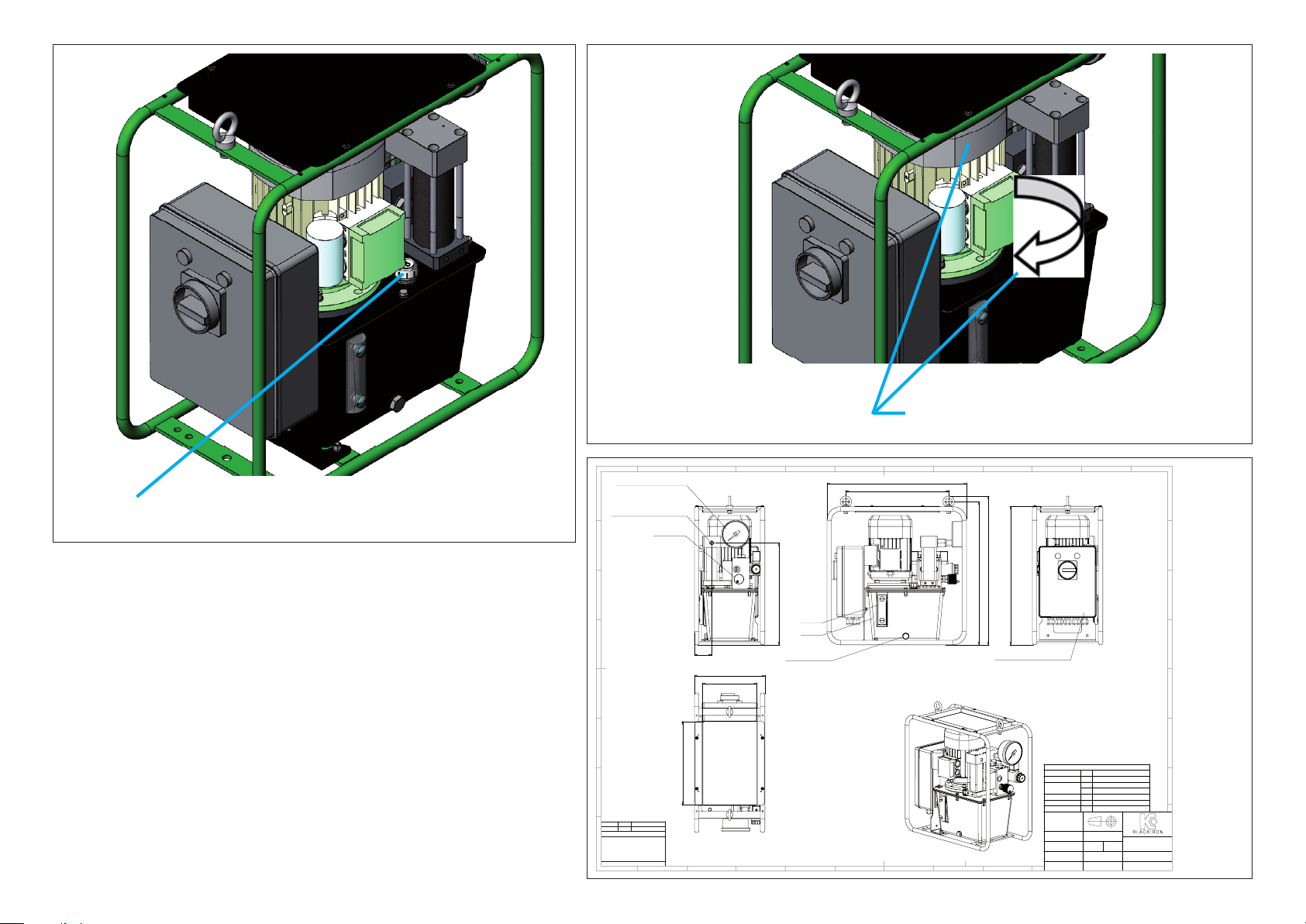
Senso orario
Clockwise turn
pag. 14
g.2
g.3
361
61
Relief valve
High pressure outlet line A
1/4"BSP CMS120°
D.100 High pressure gauge
365
495
528
508
Oil level
Oil tank
Oil discharge cap
296
192
250
491,5
Electric panel with pendant
Oil tank 6 Ltr.
usable 4,5 Ltr.
TECHNICAL FEATURES
Maximum pressure
1500 Bar
Return pressure
150 Bar
Oil flow rate
BP
3 Lt./min. up to 150 bar
HP
0,5 Lt./min. up to 700 bar
Engine power
1,1 kW
Voltage
230V-50Hz 1ph.
Usable oil volume
4,5 Lt. - Total 6 Lt.
2
1
3
4
5
6
7
8
9
10
11
12
A
B
C
D
E
F
G
1
2
3
4
5
6
7
A
B
C
D
E
F
G
8
9
DMR DATE
REVISION
DRAWING MODIFICATION HISTORY
BLACKIRON - ALL RIGHT RESERVED
- - -
THIS DRAWING IS CONFIDENTIAL. IT IS THE SOLE AND EXCLUSIVE
PROPERTY OF BLACKIRON AND IS SUBJECT TO RETURN UPON
REQUEST. IT MAY NOT BE COPIED, DUPLICATED, DISCLOSED ,
TRANSMITTED OR COMMUNICATED TO A THIRD PARTY IN ANY
MANNER, IN WHOLE OR ANY PART THEREOF, WITHOUT THE PRIOR
WRITTEN CONSENT OF THE OWNER; NOR MAY IT BE USED FOR ANY
PURPOSES OTHER THAN IN RELATION TO THE SINGLE CIRCUMSTANCE
IN CONNECTION WITH WHICH IT HAS BEEN SUPPLIED. FOR
COPYRIGHT PURPOSES THIS IS DEEMED TO APPLY EQUALLY TO THE
DOCUMENT AND TO ANY DESIGNS, CALCULATIONS, RESULTS OR
OTHER CONCEPTUAL MATTER DEPICTED THEREIN
UNLESS OTHERWISE STATED:
ALL DIMENSIONS IN MILLIMETERS
ALL UNSTATED CHAMFERS 1X45
SURFACE FINISH 3.2
REMOVE SHARP EDGES
IF IN DOUBT ASK
DO NOT SCALE DRAWING
29-04-2019
.
AB
MM
DIMENSIONS WITHOUT TOLERANCES
MEDIUM PRECISION - ISO2768
UNI EN22768
MATERIAL
CHECKED BY
DATE
SCALE
29-04-2019
29
BI-HE230V-1500 - 1500
bar electric unit
7.048.1156-2
DRAWN BY
1:3.5
DRAWING TITLE
SUP. TREAT.
DRAWING No.
DATE
WEIGHT (kg)
HEAT TREAT.
D
E
F
C
1
2
3
B
A
3
2
1
5
C
D
4
6
7
8
A
B
E
5
4
DMR DATE
REVISION
DRAWING MODIFICATION HISTORY
BLACKIRON - ALL RIGHT RESERVED
- - -
THIS DRAWING IS CONFIDENTIAL. IT IS THE SOLE AND EXCLUSIVE
PROPERTY OF BLACKIRON AND IS SUBJECT TO RETURN UPON
REQUEST. IT MAY NOT BE COPIED, DUPLICATED, DISCLOSED ,
TRANSMITTED OR COMMUNICATED TO A THIRD PARTY IN ANY
MANNER, IN WHOLE OR ANY PART THEREOF, WITHOUT THE PRIOR
WRITTEN CONSENT OF THE OWNER; NOR MAY IT BE USED FOR ANY
PURPOSES OTHER THAN IN RELATION TO THE SINGLE CIRCUMSTANCE
IN CONNECTION WITH WHICH IT HAS BEEN SUPPLIED. FOR
COPYRIGHT PURPOSES THIS IS DEEMED TO APPLY EQUALLY TO THE
DOCUMENT AND TO ANY DESIGNS, CALCULATIONS, RESULTS OR
OTHER CONCEPTUAL MATTER DEPICTED THEREIN
UNLESS OTHERWISE STATED:
ALL DIMENSIONS IN MILLIMETERS
ALL UNSTATED CHAMFERS 1X45
SURFACE FINISH 3.2
REMOVE SHARP EDGES
IF IN DOUBT ASK
DO NOT SCALE DRAWING
29-04-2019
.
AB
MM
DIMENSIONS WITHOUT TOLERANCES
MEDIUM PRECISION - ISO2768
UNI EN22768
MATERIAL
CHECKED BY
DATE
SCALE
29-04-2019
29
BI-HE230V-1500 - 1500
bar electric unit
7.048.1156-2
DRAWN BY
1:3.5
DRAWING TITLE
SUP. TREAT.
DRAWING No.
DATE
WEIGHT (kg)
HEAT TREAT.
A
g.3/1
D
E
F
C
1
2
3
B
A
3
2
1
5
C
D
4
6
7
8
A
B
E
5
4
DMR DATE
REVISION
DRAWING MODIFICATION HISTORY
BLACKIRON - ALL RIGHT RESERVED
- - -
THIS DRAWING IS CONFIDENTIAL. IT IS THE SOLE AND EXCLUSIVE
PROPERTY OF BLACKIRON AND IS SUBJECT TO RETURN UPON
REQUEST. IT MAY NOT BE COPIED, DUPLICATED, DISCLOSED ,
TRANSMITTED OR COMMUNICATED TO A THIRD PARTY IN ANY
MANNER, IN WHOLE OR ANY PART THEREOF, WITHOUT THE PRIOR
WRITTEN CONSENT OF THE OWNER; NOR MAY IT BE USED FOR ANY
PURPOSES OTHER THAN IN RELATION TO THE SINGLE CIRCUMSTANCE
IN CONNECTION WITH WHICH IT HAS BEEN SUPPLIED. FOR
COPYRIGHT PURPOSES THIS IS DEEMED TO APPLY EQUALLY TO THE
DOCUMENT AND TO ANY DESIGNS, CALCULATIONS, RESULTS OR
OTHER CONCEPTUAL MATTER DEPICTED THEREIN
UNLESS OTHERWISE STATED:
ALL DIMENSIONS IN MILLIMETERS
ALL UNSTATED CHAMFERS 1X45
SURFACE FINISH 3.2
REMOVE SHARP EDGES
IF IN DOUBT ASK
DO NOT SCALE DRAWING
29-04-2019
.
AB
MM
DIMENSIONS WITHOUT TOLERANCES
MEDIUM PRECISION - ISO2768
UNI EN22768
MATERIAL
CHECKED BY
DATE
SCALE
29-04-2019
29
BI-HE230V-1500 - 1500
bar electric unit
7.048.1156-2
DRAWN BY
1:3.5
DRAWING TITLE
SUP. TREAT.
DRAWING No.
DATE
WEIGHT (kg)
HEAT TREAT.

Cod. 7.020.0735-B - Rev. 05/2019
TAPPO DI CARICO OLIO CON SFIATO SUL SERBATOIO
RESERVOIR OIL FILL PLUG WITH BREATHER HOLE
4.1
Fare riferimento alla gura 2.
Sopra al coperchio serbatoio è installato un tappo di carico olio con
sato ½”BSP (A).
DIMENSIONI CENTRALINA Unit DIMENSIONS
4.2
COLLEGAMENTI ELETTRICI ELECTRICAL CONNECTIONS
4.3
LA CENTRALINA E’ EQUIPAGGIATA IN FABBRICA CON UNA SPINA
ELETTRICA DI TIPO COMUNE PER UNA DATA TENSIONE.
IL CAMBIO EVENTUALE DELLA SPINA PUO’ ESSERE FATTO SOL-
TANTO DA UN ELETTRICISTA QUALIFICATO, IN CONFORMITA’ A
TUTTE LE NORME ELETTRICHE LOCALI E NAZIONALI IN VIGORE.
1 - La protezione del collegamento e del circuito di linea deve essere
fornita dal cliente deve essere del 115 % della corrente a pieno
carico del motore alla pressione massima di funzionamento.
2 - Per maggiori informazioni, fare riferimento alla targhetta dei dati
tecnici per i dati di potenza.
3 - Vericare che il motore giri in senso orario come indicato dalla freccia
in gura 3/1.
Nota: Tutte le operazioni sull’impianto elettrico devono essere effet-
tuate da un elettricista qualicato.
Refer to gure 2.
On the top of the reservoir is installed in the oil ll plug with breather.
Refer to gure 3 for unit dimensions.
THE Unit IS FACTORY EQUIPPED WITH THE COMMON ELECTRICAL
PLUG FOR A GIVEN VOLTAGE.ALTERING THE PLUG TYPE SHOULD
ONLY BE DONE BYA QUALIFIED ELECTRICIAN, ADHERING TO ALL
APPLICABLE LOCAL AND NATIONAL CODES.
1 - The disconnect and line circuit protection to be provided by customer.
Line circuit protection to be 115% of motor full load current at
maximum pressure of application.
2 - For more information, refer to unit name plate for power rating.
3 - Verify that the motor turns clockwise as indicated by the arrow in
gure 3/1.
Note: All operations on the electrical system must be performed by a
qualied electrician.
pag. 15
Fare riferimento alla gura 3 per le dimensioni della centralina.

Cod. 7.020.0735-B - Rev. 05/2019
g.5
g.4
1800bar/25.740psiWP
Centralina elettrica
Electric unit
Tensionatore idraulico
Bolt tensioner
ConnessioneG1/4”concono120°maschio
G 1/4” male thread with 120° external cone
pag. 16
Livello olio
Oil level

Cod. 7.020.0735-B - Rev. 05/2019
LIVELLO DELL’OLIO OIL LEVEL
4.4
Controllare il livello dell’olio prima di avviare la centralina; aggiungere
olio, se necessario, togliendo il tappo di carico olio con sato ½” BSP
dal coperchio serbatoio (vedere gura 2).
Il serbatoio è pieno, quando il livello dell’olio è come mostrato in gura 4.
La centralina è dotata di livello olio elettrico che segnala il livello minimo
all’interno del serbatoio. Nel caso di intervento si accende la luce rossa
sul quadro elettrico ed il motore non funziona.
IMPORTANTE: Aggiungere olio solo quando tutti i componenti del
sistema sono ritornati a riposo, altrimenti il sistema
conterrebbe più olio di quanto ce ne possa stare.
COLLEGAMENTO IDRAULICO TUBI FLESSIBILI HYDRAULIC HOSES CONNECTIONS
4.5
Collegare i tubi essibili come mostrato in gura 5.
Usare tubi essibili marcati “1.800 bar/25.740 psi WP”. Gli innesti
idraulici debbono essere installati come in gura 5 per il corretto fun-
zionamento del tensionatore idraulico. Accertarsi che gli innesti idraulici
siano completamente inseriti prima di lavorare.
Un inserimento solo parziale dell’innesto impedirà il corretto funziona-
mento del tensionatore idraulico
Nota: Quando il tensionatore idraulico è collegato alla centralina, ri-
marrà dell’aria intrappolata nel circuito idraulico. Spurgare l’aria
ponendo il tensionatore ed i tubi essibili stesi e raddrizzati al
di sotto della centralina, fare funzionare il tensionatore senza
carico no a che si muova senza esitazione.
Check the unit oil level prior to start-up, if necessary add oil by removing
the oil ll plug with breather hole ½” BSP from the cover plate (see gure
2).
The reservoir is full when the oil level is as shown in gure 4.
The unit is equipped with oil level electrical signals, the minimum level
within the tank. In the case of action turns on the red light on the electrical
and the motor is not working.
IMPORTANT: Add oil only when all system components are fully
retracted, or the system will contain more oil than the
reservoir can hold.
Connect hoses as shown in gure 5.
Use hoses rated “1.800 bar/25.740 psi WP”. Couplers must be
assembled per gure 5 for correct bolt tensioner operation. Ensure
couplers are fully engaged before operating.
Partial coupler engagement will prevent proper wrench operation.
Note: When the bolt tensioner is rst connected to the unit, air will
be trapped in the hydraulic circuit. Remove air by placing bolt
tensioner and straightened hoses below unit, operate bolt
tensioner without load until it move without hesitation.
pag. 17

Cod. 7.020.0735-B - Rev. 05/2019
g.7g.6
OFF
ON
O
I
2-ON-RITORNO/RETRACTS
1-ON-AVANTI/ADVANCE
3 - OFF
pag. 18
LIVELLO OLIO BASSO
OIL LEVEL LOW

Cod. 7.020.0735-B - Rev. 05/2019
FUNZIONAMENTO OPERATION
5.0
INTERRUTTORE ON-OFF SUL QUADRO ELETTRICO
Unit ON-OFF SWITCH
5.1
Fare riferimento alla gura 6.
1 - ON - Centralina comandata con un telecomando pensile. La
centralina si avvia quando si ruota l’interruttore su ON e si
accende la luce verde.
2 - OFF - Telecomando pensile disabilitato. La centralina non si avvia
quando si preme il pulsante ON.
FUNZIONAMENTO DEL TELECOMANDO REMOTE CONTROL OPERATION
5.2
Fare riferimento alla gura 7.
1 - Pulsante ON- (1) del telecomando:
• Pulsante premuto – Il motore si commuta su ON. Il tensionatore
idraulico AVANZA no a che si tiene premuto il pulsante.
• Pulsante rilasciato – Il motore continua a girare per ulteriori 20
secondi, il tensionatore idraulico rimane in pressione nella posi-
zione dove si trova.
2 - Pulsante ON- (2) del telecomando:
• Pulsante premuto – Il motore si commuta su ON. Il tensionatore
idraulico RITORNA.
• Pulsante rilasciato – Il motore continua a girare per ulteriori 20
secondi, il tensionatore idraulico ritorna in posizione di riposo, la
pressione nel circuito si scarica.
3 - Pulsante OFF (3) del telecomando:
• Pulsante premuto – Il motore commuta su OFF immediatamente.
Nota: riarmare il pulsante dopo averlo premuto per ripristinare la con-
dizione di lavoro del telecomando.
Refer to gure 6.
1 - ON - Unit operated with a remote control. The units starts when
you turn the switch ON and the light turns green.
2 - OFF - Remote control disabled. Unit will not start when remote
control ON button is depressed.
Refer to gure 6.
1 - Remote control ON- (1) button:
• Button depressed - Motor turns ON. Bolt tensioner ADVANCES
for as long as button is held down.
• Button released - The motor continues running for up to 20
seconds, the bolt tensioner remains under pressure in the position
where it is.
2 - Remote control ON- (2) button:
• Button depressed - Motor turns ON. Bolt tensioner RETRACTS.
• Button released - The motor continues running for up to 20
seconds, the bolt tensioner back in resting position and the
pressure in the circuit is unloaded.
3 - Remote control OFF (3) button:
• Button depressed - Motor turns OFF immediately.
Note: rearm after having pressed the button to restore the working
condition of the remote control.
pag. 19

Cod. 7.020.0735-B - Rev. 05/2019 pag. 20
This manual suits for next models
2
Table of contents
Popular Power Supply manuals by other brands

Videx
Videx 520MR Installation instruction

Poppstar
Poppstar 1008821 Instructions for use

TDK-Lambda
TDK-Lambda LZS-A1000-3 Installation, operation and maintenance manual

TDK-Lambda
TDK-Lambda 500A instruction manual

Calira
Calira EVS 17/07-DS/IU operating instructions

Monacor
Monacor PS-12CCD instruction manual


