Blackrock Microsystems 9027301 User manual

Page 1
12x20x9.3 Ft. ROUND SHELTER
Owner’s Manual
Items #9027301
\
Tools required for assembly (not included)
Page 2
TABLE OF CONTENTS
SAFETY AND PRE-ASSEMBLY CAUTIONS……………………………………………………….…………………………………………………….2
PARTS LIST…………………..………………………………………………………………………………………………………………………………3
ASSEMBLY INSTRUCTIONS………..…………….…………………………………………………………………………………………………..…4-9
SAFETY and PRE-ASSEMBLY CAUTIONS
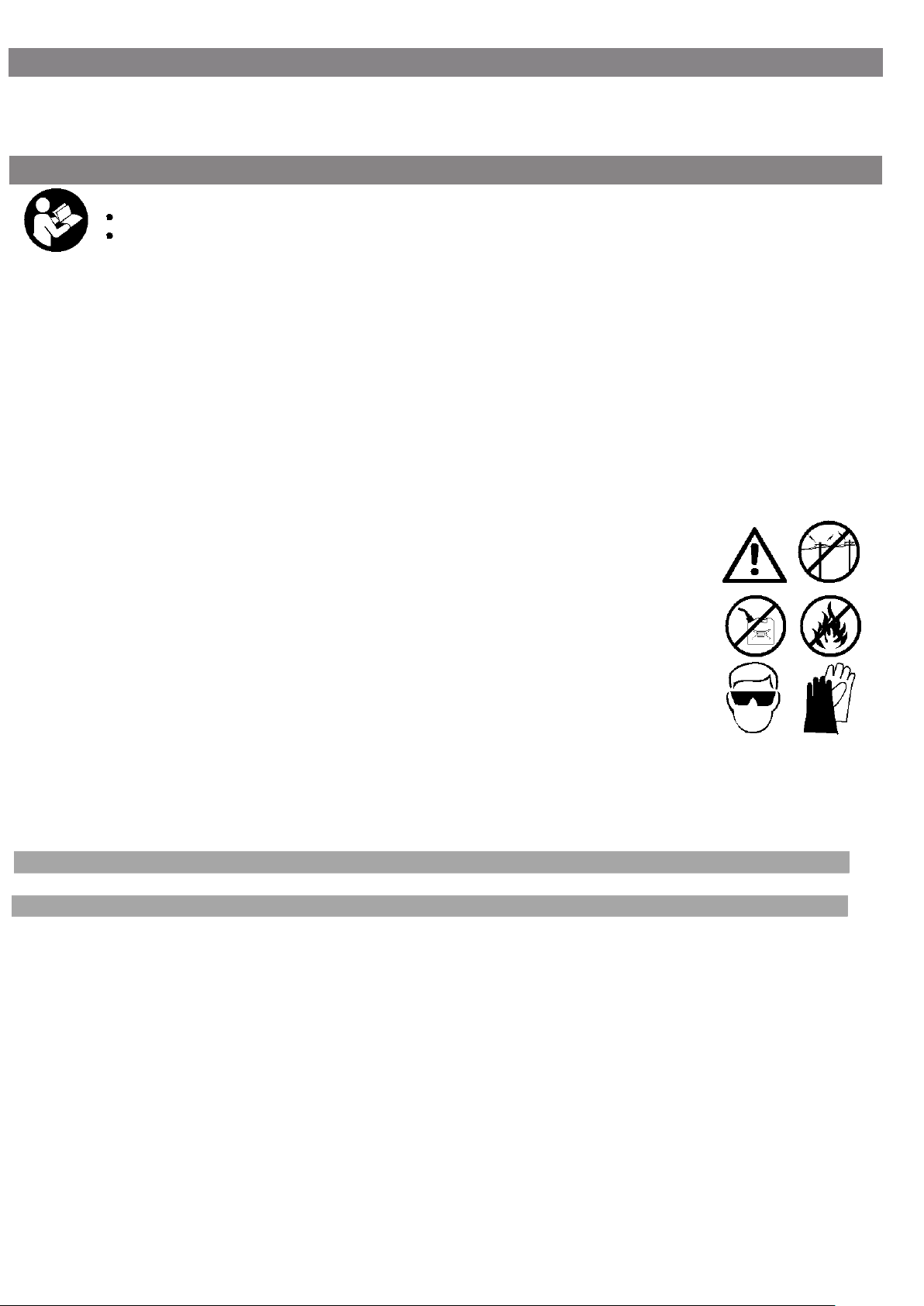
WARNING!
Read all safety instructions to reduce the risk of injury or death.
No responsibility is accepted by Canadian Tire for damages or injuries resulting from improper installation or noncompliance
This is a temporary structure and is not recommended as a permanent structure.
Choose your shelter's location carefully. Check for overhead utility lines, branches, etc. DO NOT install near roofs or other structures that may
shed snow, ice or excessive run-off onto your shelter. Keep away from electrical wires!
Install your shelter on a level surface.
Check municipal by-laws prior to setting up the product.
Have an overview of all parts before attempting installation. Make sure all components are available.
DO NOT use this product in environments for which it is not intended (i.e. extreme cold, high winds, extreme heat, heavy rainfall, etc).
Always wear safety glasses when assembling this product. Wear gloves when working with tubing to prevent cuts or abrasions.
Caution! Anchors must be used with all shelters. Covers should NOT be installed on any product until it has been properly anchored to the
ground.
Proper anchoring and keeping cover tight and free of snow and debris, is the responsibility of the consumer. Damages caused by improper
anchoring are not covered under warranty.
Warning! Keep all flame and heat sources away from the shelter fabric. The fabric will burn if left in continuous
contact with a flame source.
DO NOT use open flames or cooking or heating devices inside or in close proximity to the product, including all
types of stoves, gas heaters, gas lanterns, citronella torches, mosquito coils, etc.
Warning! In order to reduce risk of burning and avoid damage, DO NOT
-cook, smoke, refuel or use any open flame devices in or around the shelter.
-store flammable liquids (gasoline, kerosene, propane, etc.) in the shelter.
-operate gas powered vehicles/equipment in or around the shelter.
Keep open flames a safe distance away from the shelter.
DO NOT use hard-edged tools or instruments, such as rakes or shovels, to remove snow. These can cause punctures to the cover.
NEVER start the engine of any vehicle or machine inside a closed shelter. Ensure that there is adequate ventilation for starting engines and for any work with paints,
cleaners, etc.
This shelter is NOT designed to support heavy snow or ice loads. Snow or ice accumulation may cause your shelter to collapse. To avoid overload, brush snow and
ice off the roof top with a broom or mop.
To prevent collapse, damage to property, personal injury and/or death, NEVER clear the roof of snow or debris from inside the shelter.
DO NOT use bleach, alkaline or harsh detergents for cleaning. Doing so will damage the polycarbonate material. Soap and warm water are recommended.
INTENDED USE
This temporary shelter is intended to offer protection from damage caused by the sun, light rain, light snow, tree sap, bird and animal excrement.
CLEANING AND MAINTENANCE
Do NOT apply any polishing or protective products to the roof tarp and panels or use harsh abrasives, bleach or cleansers. Roof tarp and panels can beeasily
cleaned with mild soap and water.
Periodically check the anchors, the tension of the ropes and all hardware to ensure the stability of the shelter during use. It may be necessary to tighten the cover
and the back/door panels. Be sure that all covers and panels are kept tight.
Store your shelter in a cool, dry location between seasons to prolong the service life of all components. Components are not equally durable and may require
replacement over time at different intervals.
Please note that the Manufacturer has no control over the elements such as wind, heavy snow or rain. The
Manufacturer cannot control the location or soil conditions into which the shed is placed. The Manufacturer, without
control of the elements, location or soil conditions, cannot be held responsible for damages caused by the shed to
other items or damages to the shed itself
Page 3
ASSEMBLY
Please read instructions fully before beginning assembly
Step 1: Checking the Parts
Unpack and check the contents of the box. Make sure that you have all the parts described in the parts list shown hereafter
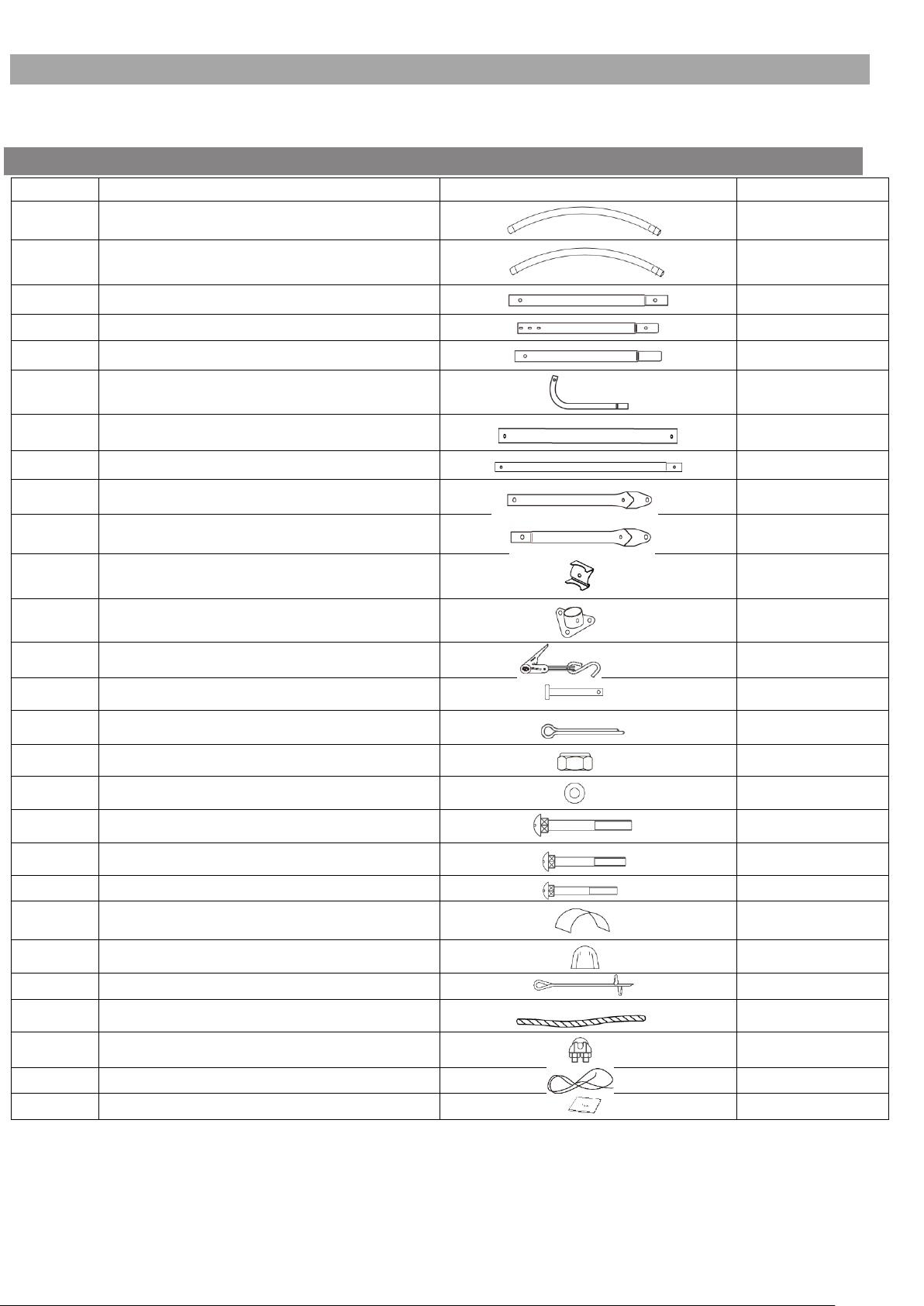
PART LIST
NO.
Description
Illustration
Q’ty
1
Top Roof Tube
6
2
Rafter Roof Tube
12
3
Corner Leg Tube
4
4
Center Leg Tube (Top Part)
8
5
Center Leg Tube (Bottom Part)
8
6
Corner Bent Leg
4
7
Cross Rail Tube
5
8
Cross Rail Tube (with male end)
20
9
Support Brace (1st half)
4
10
Support Brace (2nd half)
4
11
Tube Connector
24
12
Foot Plate
8
13
Ratchet Tie Down
8
14
Pin Bolt
8
15
Cotton Pin
8
16
M6 Nut
50
17
M6 Washer
50
18
M6X80 Bolt
30
19
M6X45 Bolt
16
20
M6X35 Bolt
4
21
Roof Tarp
1
22
Front Door Panel (with zipper)
2
23
15" Auger Anchor
6
24
Cable 1'-Length
6
25
Cable Clamp
6
26
Rope
2
#
Owner's Manual
1
"#" Indicates a non-illustrated part

Page 4
ASSEMBLY PREPARATION
Place all parts from the packaging box in a cleared area and arrange them on the ground in front of you.
Remove all packaging materials and place them back in the box. Do not dispose the packaging materials until assembly is complete.
Check for completeness and transport damages.
WARNING!
Do not place the product under trees from which hard fruit such as apples, walnuts or heavy pine cones, etc., may fall.
Keep children away during assembly. This product contains small parts which can be swallowed by children.
Do not attempt to assemble the product if any parts are missing.
At least 2 people are needed to complete the assembly as some of the steps require heavy lifting.
ASSEMBLY
WARNING!
Do not leave the shelter unattended during assembly. Otherwise, personal injury or damage to the shelter may occur!
Frame assembly overview
Diagram A
Diagram A below represents the completed Frame Assembly once steps 1-2 are completed.
Note: 4 or more people are required for safe and accurate assembly.

Page 5
ASSEMBLY
Step 1: Frame Assembly
Select level and suitable location for your shelter.
1. Assembly the two End Ribs
a. Follow Diagram B connecting the 7 tubes
together
(1pc tube #1, 2pcs tube #2, 2pcs tube #3 & 2pcs
Bent Legs #6) to form 1 End Rib.
b. Repeat it to get the other End Rib.
2. Assembly the 5 Center Ribs
a. Follow Diagram C connecting these 7 tubes together
(1pc tube #1, 2pcs tube #2, 2pcs tube #4 & 2pcs tube
#5) to
form 1 Center Rib.
b. Repeat it to get the other 4 Center Ribs.
c. Insert the Center Ribs into the Foot Plate (#12). Align holes
in the pole and foot plate, push the Pin Bolt (#14) through
all the holes, Insert the Cotter Pin (#15) and split the
tongues of the cotter pin with a slot screwdriver to secure
this connection.
Use a rubber or wooden mallet to ensure all
pipes are fully inserted.
3. Attach Side Cross Rails
a. Pick one End Ribs & 4 Tube #7. Follow Diagram D use
part #11 connecting Tube #7 and the End Rib by fittings
(#16, #17 & #18).
Diagram B
Diagram C
Diagram D

Page 6
ASSEMBLY
B Insert the male end of tube #8 into tube #7. See
Diagram E
C Connect the two parts of Support Brace (#9 & #10) by
Fittings (#16, #17 & #20)
D Fix one end of the Support Brace on tube #3 by Fittings
(#16 #17 & #119). And Fix the other end of the Support
Brace with tube #2, #7 & #8 by Connector #11 and fittings
(#16, #17& #18).
E Repeat above steps, connecting all the rest 3 Center Ribs
And last end Ribs, you will get the whole frame finished as
Diagram F
Note: The other set of Support Brace needs to be
assembled in an opposite way with the 1st set.
4. Attach Top Cross Rails
a. Connect Tube #7 with the End Rib with fittings
(#16,#17,#18) and please fix tube #7 under the Rib top See
Diagram, G
b. Insert Tube #8 into tube #7, and fix it to the next Center
Rib by fittings (#16, #17 & #18). And now please follow
Diagram G and fix Tube #8 on top of the Rib.
Note: The end of last Tube #7 still needs to be
fixed and the End Rib.
Diagram E
Diagram F
Diagram G

Page 7
ASSEMBLY
5. Square and Anchor the Frame
a) Check the measure of frame both 12' at the front
and back corners, as well as the center.
b) Take a diagonal measure as shown in Diagram
H. When these two measures are equal the frame
is square. Adjust the frame until they are equal to
within 1".
c) Once equal check the width measures again to
ensure all are equal at 12'.
d) Next, install Anchors (Part #23, #24 & #25) at the
4 Corner bent legs by screwing the removable
anchor (#23) into the ground and to the inside of
the shelter. Secure with cable (#24) and cable
clamp (#25) as shown in Diagram I
e) Install Anchors (Part #23, #24 & #25) at the two
Sides Center legs tube by screwing the
removable anchor (#23) into the ground and to
the inside of the shelter. Secure with cable (#24)
and cable clamp (#25) as shown in Diagram I.
Step 2: Tarp Assembly
1. Installing the Front and Back Covers.
The front cover contains a zippered door to allow entry and
exit to the shelter. Ensure to locate this cover to the desired
end. Also ensure the zipper is in the 'closed' position while
installing.
Repeat it to get the other 1 Front Covers
a. Begin with the front cover and first locate the webbed belt that runs
the perimeter of the cover. The webbing is exposed at the peak,
the shoulders and the feet of the cover. At the feet of the cover,
the webbing has two loose ends. Tie off the two loose ends of
the webbed belt, one to each of the two corner legs.
b. Next, disconnect the 5 Cross Rails ends which connected with
End Rib.
c. Wrap the Door cover edge around the End Rib. See Diagram J.
Diagram H
Diagram I
12 5
23
23
Diagram J

Page 8
ASSEMBLY
d. Insert the Cross Rail into each hole on the Door edge, and slip the
webbed belt to be outside of the tube. Rejoin the pipes. See
Diagram K1, K2, K3.
e. Next, taking 1-pieceRatchet (Part #13), untie one end of the webbed
belt at the foot of the leg and insert the belt to the ratchet as shown
in the Diagram K4 Ratchet a few times to tighten the belt to the
ratchet. Diagram K5 Next insert the S-hook of the
ratchet into thefoot of theCorner Leg and ratchet up/ down a couple
of times to hold the ratchet and belt in place. Diagram K6
f. Repeat for the other loose end of the webbed belt.
g. While one person remains on the stool and standing at the peak of
the shelter, the other person tightens the ratchet, first at the foot of
one corner leg and then moving over to the foot of the other corner
leg.
h. The person standing at the peak assists by ensuring the tarp is
partially folded over the pipes of the end rib and inside or toward
the interior of the shelter.
i. Ensure the overlap of the cover flap remains square over the end
rib and reaches the ground at the base while tightening the
ratchets.
2. Installing the Main Cover
a. Lay the cover on the ground next to the frame with inside
of the cover (the side with eyelets) facing down and the
webbing on the front and rear of the corner of the building.
Diagram L.
b. Tie a rope to the eyelets of the cover, each side one rope.
(If you have enough people to work together, suggest you
add another rope in the middle
c. Pull cover over the frame by the help of the
rope as Diagram M, making sure to center cover on
frame. There should be an equal amount of
overhanging at all four corners.
Diagram K.
K1 K2 K3
K4 K5 K6
Diagram L
Diagram M

Page 9
ASSEMBLY
d. Assemble the ratchets (Part #13) to the web ends on the
4 corner of the cover, 1pc for each corner.
e. Insert the "S" - hook on ratchet into hole on the Bent
Corner Leg. Wind the ratchet so that the webbing
overlaps itself. Do not over tighten.
f. Follow below Diagram N, lacing the Cover with the
bottom Cross Rails through the eyelets on the Cover
bottom part. Make sure the Cover is even in front & back,
also even in the 2 sides. Lacing the Cover tight on the
frame.
g. Tight the Ratchet again based on the Tarp tightness.
NOTE: Over-tightening can cause damage to
straps and/or the anchor point.
DO NOT over-tighten!
The shelter is now ready for use.
Note: Please check periodically (two to three times
in the first week - weekly for the balance of the first
month of set up) and tighten ratchet tie-downs and
all hardware as needed. Monthly inspection is
recommended throughout usage.
Disassembly
When disassembling the shelter, depress the spring-
loaded bar and open ratchet handle completely to
allow the webbed belt to disengage the ratchet.
PLEASE RE-READ ALL WARNINGS CONTAINED
ON PAGE 2 OF THESE INSTRUCTIONS. SAVE
THESE INSTRUCTIONS FOR FUTURE USE.
To dismantle, execute all instructions in reverse order.
Store your shelter in a cool, dry location between
seasons to prolong usable life of all components.
Components are not equally durable and will require
replacement over time at differing intervals.
Diagram N
.

Page 10
Distributed by
Forcome (shanghai) Co., Ltd
South Sizhuan Road,Shanghai 201612
Made in China
Table of contents
Popular Shelter manuals by other brands

Clam Corp
Clam Corp CLAM 2000 quick start guide

Duratuf KIWI
Duratuf KIWI SHEDS MK4A Assembly instructions

Trigano Jardin
Trigano Jardin J-87905P1 manual

Shelters4Less
Shelters4Less SR1556 Assembly instructions

Sojag
Sojag Octogonal Sunshelter 12x15 Assembly manual

ShelterLogic
ShelterLogic 51351 Assembly instructions

ZORO
ZORO 11C543 Operating instructions and parts manual

ShelterLogic
ShelterLogic ShelterCoat 12'W x 8'H Peak manual
Arrow Storage Products
Arrow Storage Products CPHC101507 Owner's manual & assembly guide

G21
G21 WOH 181 - 242 x 75 Assembly instructions

No Butts Bin
No Butts Bin SR1562 Assembly instructions

Sunjoy
Sunjoy A10200810 Assembly instruction


