Blackshape Prime Technical specifications

CF 300 –Flight Manual sect. 1 - General
BY BLACKSHAPE
Document n° BPU/FM003
Rev 3 dtd 03/06/2014 Page 1
-66
SECTION 1
GENERAL
INDEX
1.1. INTRODUCTION
1.2. WARNINGS, CAUTIONS AND NOTES
1.3. THREE-VIEW DRAWING OF THE AIRPLANE
1.4. MAIN DIMENSIONS
1.5. CONTROL SURFACES TRAVEL
1.6. ENGINE
1.7. PROPELLER
1.8. FUEL
1.9. LUBRICANT
1.9.1 Table of Lubrication oils
1.10. COOLING LIQUID
1.10.1 Table of Mixture Ratios
1.11. WEIGHT
1.12. LIST OF DEFINITIONS AND ABBREVATIONS
1.12.1. Airspeeds
1.12.2. Flight Performance and Flight Planning
1.12.3. Powerplant
1.12.4. Weight and Balance
1.12.5. Meteorology
1.13. CONVERSION FACTORS
1.13.1. Conversion of units of measurement
1.13.2. Conversion liters/US gallons
1.14. MISCELLANEOUS
UNCONTROLLED

CF 300 –Flight Manual sect. 1 - General
BY BLACKSHAPE
Document n° BPU/FM003
Rev 3 dtd 03/06/2014 Page 2
-66
1.1. INTRODUCTION
The safe use of the aircraft in accordance with the instructions provided in this Flight Manual shall
guarantee to you hours of safe and entertaining flying.
We ask you to carefully read this Flight Manual. We ask you to make an appropriate use of this manual
and to fully comply with the instructions, flight parameters and warnings listed below at any time you
use the aircraft.
For all information about systems and sub-systems, including operational limitations, please refer to the
Technical Description (Document RT002) which forms part of this handbook.
1.2. WARNINGS, CAUTIONS AND NOTES
The following definitions apply to articles: warnings, cautions and notes used in the Flight Manual.
The manufacturer declines any responsibility in case of reduction of safety due to non-compliance by
the user with texts marked with "WARNING", "CAUTION" and "NOTE".
UNCONTROLLED
CF 300 –Flight Manual sect. 1 - General
BY BLACKSHAPE
Document n° BPU/FM003
Rev 3 dtd 03/06/2014 Page 3
-66
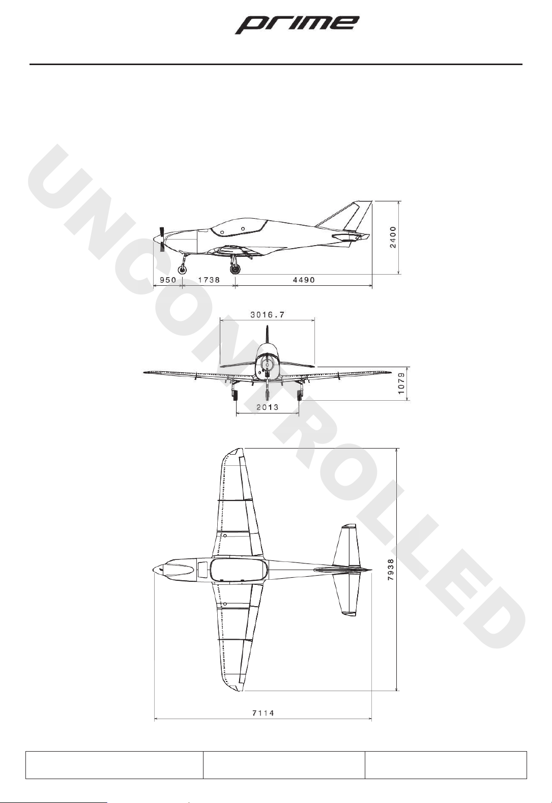
1.3. THREE -VIEW DRAWING OF THE AIRPLANE
The following figure is a three-view drawing of the aircraft CF-300.
·The dimensions listed here (in mm) correspond to an aircraft weighting 472.5 kg with tires inflated at
normal operating pressure.
UNCONTROLLED

CF 300 –Flight Manual sect. 1 - General
BY BLACKSHAPE
Document n° BPU/FM003
Rev 3 dtd 03/06/2014 Page 4
-66
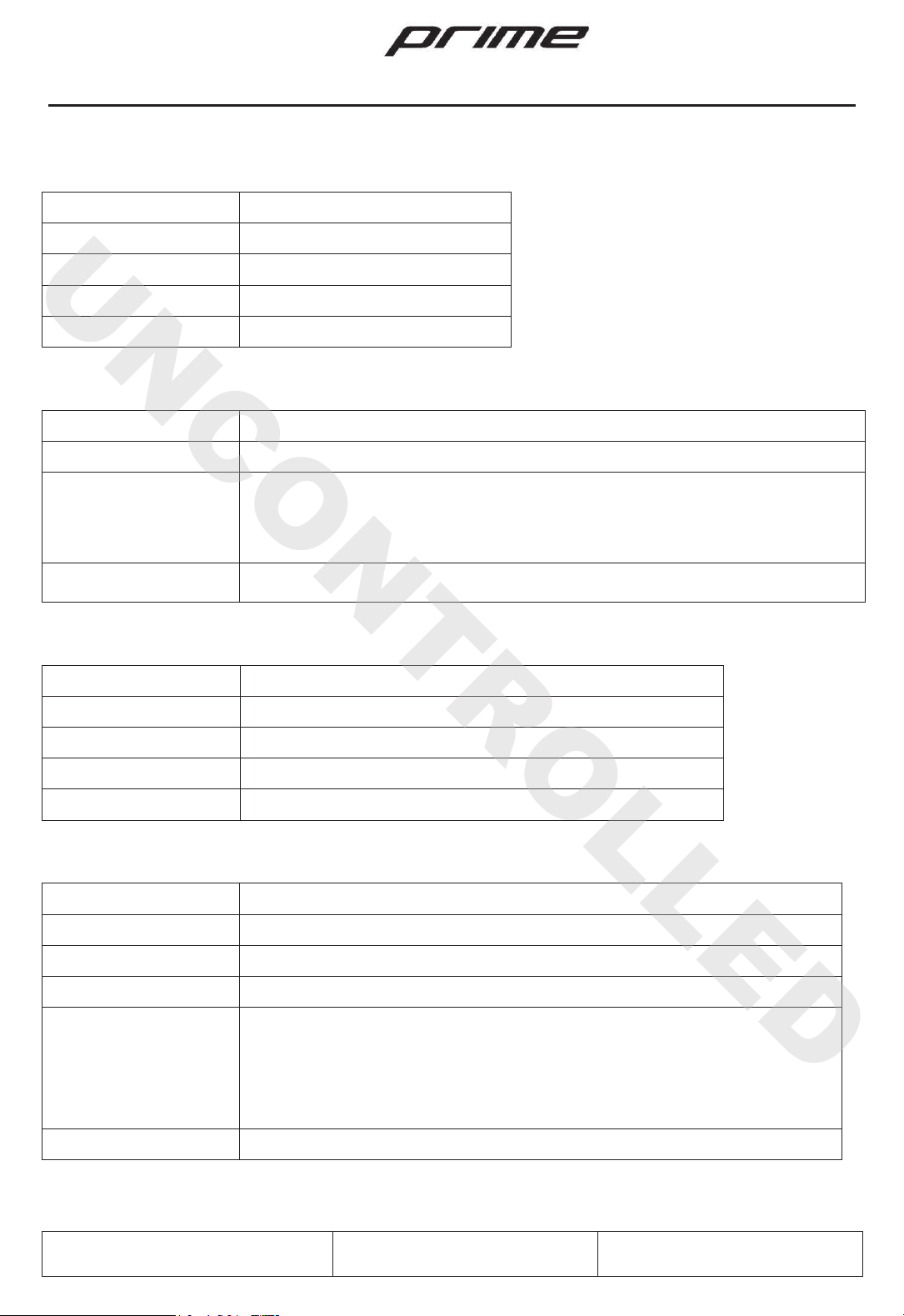
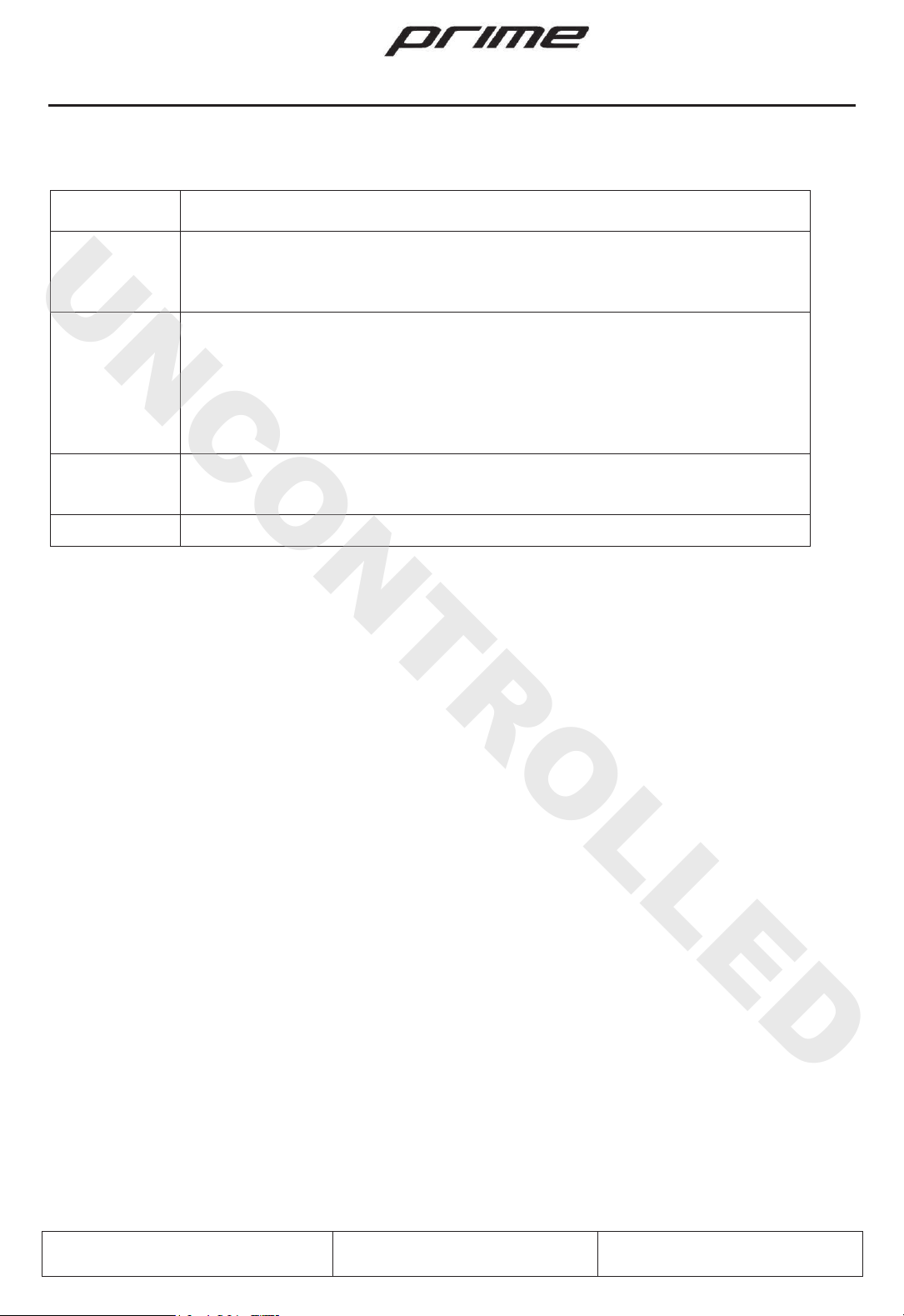
1.4. MAIN DIMENSIONS
WING
Wingspan
7,94 m
Mean Aerodynamic Chord (MAC)
1,3 m
Wing Area
9,6 m2
Wing Loading
49,2 kg/m2
Aspect Ratio
6,75
Taper Ratio
2,133
Dihedral
4°
FUSELAGE
Total Length
7,15 m
Maximum Width
0,79 m
Total Height
2,41 m
TAIL PLANES
Horizontal Stabilizer Span
3,02 m
Fin Height
0,83 m
LANDING GEAR
Track
2,01 m
Wheel Base
1,76 m
Main Tires Size
4”
Wheels and Brakes
Beringer
Nose Tire Size
3”
UNCONTROLLED
CF 300 –Flight Manual sect. 1 - General
BY BLACKSHAPE
Document n° BPU/FM003
Rev 3 dtd 03/06/2014 Page 5
-66
1.5. CONTROL SURF ACES TRAVEL
Ailerons
+15° -11°
Elevator
+20° -10°
Trim
+6° -30°
Rudder
+20° -20°
Flaps
10° 20° 30°
1.6. ENGINE
Model:
ROTAX 912 ULS3
Manufacturer:
Rotax Gmbh
Engine type:
4 horizontally-opposed cylinders with a total displacement of 1352 cm3, mixed
cooling (liquid
-cooled heads, air-
cooled cylinders), dual carburetors, integrated
gearbox (2.4286:1) with torque damper.
Compression ratio 11:1
Maximum power:
100 hp (73.5 Kw) at 5800 RPM –max 5 min.
1.7. PROPELLER
Manufacturer:
MT Propeller
Model:
MTV-33-1-A
Number of blades:
2
Diameter:
1750 mm
Type:
Hydraulic controlled variable pitch
1.8. FUEL
Fuel (*):
Min. RON 95
En 228 Super
En 228 Super plus
AVGAS 100LL
Fuel tank:
2 anti-blast tanks, installed into the central wing, one left one right with the
capacity of 33 liters each.
2 option auxiliary anti
-blast tanks, installed into the outer wing, one left
one
right, with the additional capacity up to 15 liters each
Total fuel capacity:
66 liters (96 liters optional)
(*) Refer to the “Rotax Operator’s Manual”
UNCONTROLLED

CF 300 –Flight Manual sect. 1 - General
BY BLACKSHAPE
Document n° BPU/FM003
Rev 3 dtd 03/06/2014 Page 6
-66
1.9. LUBRICANT
Lubrication system:
Forced, with external tank.
Lubri
cant (*):
Use
API “SG” type oil or similar.
The type of lubricant used may
vary with climatic conditions of use
(see Table below).
Lubricant quantity:
Max. 3 liters
Min. 2 liters
(*)Refer to the “Rotax Operator’s Manual”
1.9.1. Table of Lubrication oils
Depending on the external temperature when using the aircraft, adjust the type of
lubricant oil used, according to the SAE viscosity grades, as shown in the following
table:
UNCONTROLLED
CF 300 –Flight Manual sect. 1 - General
BY BLACKSHAPE
Document n° BPU/FM003
Rev 3 dtd 03/06/2014 Page 7
-66
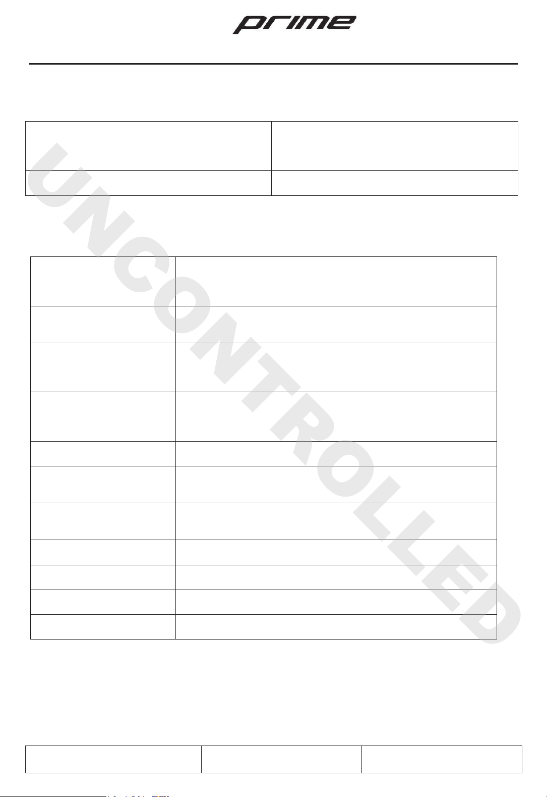
1.10. COOLING LIQUID
Cooling system:
Mixed air/liquid cooling, with closed and pressurized circuit.
Liquid (*):
Use mainly those two types of cooling liquids
:
1)
Conventional based on ethylene glycol
2)
Propylene glycol
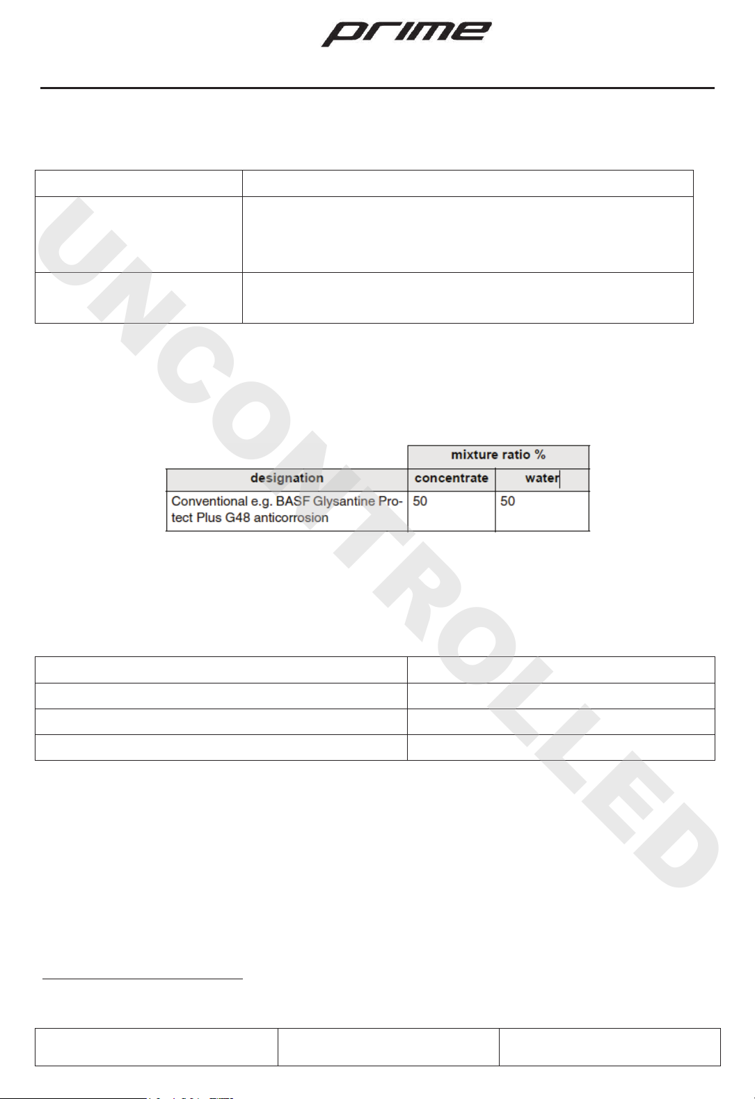
Mix
ture ratio:
The cooling liquid shall be mixed with water in the proportions
indicated in the following table
(*) Refer to the “Rotax Operator’s Manual”
1.10.1. Table of Mixture Ratios
1.11. WEIGHT
Maximum Take-Off Weight (MTOW)1
472,5 Kg (1041 lbs)
Maximum Landing Weight
472,5 Kg (1041 lbs)
Empty Weight
See Chapter Mass and Balance
Maximum Useful Load (MTOW –Empty Weight)
See Chapter Mass and Balance
1 With ballistic rescue system installed
UNCONTROLLED

CF 300 –Flight Manual sect. 1 - General
BY BLACKSHAPE
Document n° BPU/FM003
Rev 3 dtd 03/06/2014 Page 8
-66
1.12. LIST OF DEFINITIONS AND ABBREVATIONS
1.12.1. Airspeeds
CAS
Calibrated A
irspeed: Indicated airspeed, corrected for
installation and instrument
errors. CAS equals TAS at
standard atmospheric conditions (ISA) at
medium sea
level (
MSL).
GS
Ground Speed
:Speed of the airplane relative to the ground.
IAS
Indicated Airspeed
:Indicated Airspeed as shown on an airspeed indicator.
TAS
True
Airspeed: The speed of the airplane relative to the air.
TAS is CAS corrected
for errors due to altitude and
temperature.
V
FE
Maximum Flaps Extended Speed
:This speed must not be
exceeded with the
given flap setting.
V
LE
Maximum landing gear extended speed
:
This is the maximum speed at which it is
safe to fly with the landing gear extended.
V
LO
Maximum landing gear operating speed
:
This is the maximum speed at which it
is safe to extend or retract the landing gear
.
V
NO
Maximum Structural Cruising Speed
:This speed may be
exceeded only in
smooth air. It corresponds to the top end of the green arc on the airspeed indicator.
V
A
Maneuvering Speed
:
It is the recommended airspeed when flying in turbulent air.
This is the m
aximum speed at which the airplane is
not overstressed at full
deflection of control surfaces. Full or
abrupt control surface movement is not
permissible above this
speed.
V
NE
Never Exceed Speed
:This speed must NOT be exceeded in any operation.
V
S
Stall speed:
The power-off stall speed with
the airplane in its standard
configuration.
V
S0
Stall speed in landing configuration:
The power-
off stall speed with the airplane
in landing
configuration (gear and flaps extended).
V
X
Best Angle
-of-Climb Speed.
V
Y
Best Rate
-of-Climb Speed.
V
r
Rotation Speed
:
This is the speed at which the aircraft rotates about its pitch axis
during take
-off.
V
REF
Reference Speed
.
UNCONTROLLED
CF 300 –Flight Manual sect. 1 - General
BY BLACKSHAPE
Document n° BPU/FM003
Rev 3 dtd 03/06/2014 Page 9
-66
1.12.2 Flight Performance and Flight Planning
DEMONSTRATED Crosswind component
The maximum speed of the crosswind component
at
which the maneuverability of the airplane
during
take-off and landing has been
effectively
demonstrated during test flights.
Service ceiling
The altitude at which the maximum rate of climb is
0.5 m/s (100 ft/min).
1.12.3. Powerplant
RPM
Number
of revolutions per minute:
the number of engine
revolutions per minute
, divide by 2.4286 (912 ULS3)
to obtain the
number of propeller revolutions per minute.
Throttle Lever
The lever which controls the engine power
, and
therefore the
manifold absolute
pressure (MAP).
Propeller Lever
Regulation of the propeller pitch setting:
this is a control
lever
that allows to set the propeller pitch
, and as a consequence
, the
engine RPM
.
Tachometer
Indicates the number of revolutions per minute of the engine.
The instrument is connected directly to the engine via a flexible
hose.
Cylinder Head Temp. (CHT)
Indicates the head temperature of the cylinder
n° 3.
Exhaust Gas Temp. (EGT)
Indicates the temperature of the gas that are expelled directly
from the cylinders.
MAP
Manifold pressure display
:
Indicates the engine absolute
manifold pressure.
Fuel Pressure
Fuel pressure indicator
Voltmeter
Indicates the battery load
Water temp.
Indicates the cooling water temperature
Oil Temp.
Indicates the engine oil
temperature
UNCONTROLLED

CF 300 –Flight Manual sect. 1 - General
BY BLACKSHAPE
Document n° BPU/FM003
Rev 3 dtd 03/06/2014 Page 10
-66
1.12.4. Weight and Balance
Reference
Datum (RD)
An imaginary vertical plane from which all horizontal
distances for
the center of gravity calculations are
measured.
Lever arm
The horizontal distance from the reference datum to the center of
gravity (of a component).
Moment
The weight of a component multiplied by its lever
arm.
Sta
tion
A defined point along the longitudinal axis which is
generally
presented as a specific distance from the
reference datum.
Center of gravity (
C.G.)
Point
of equilibrium for the airplane weight.
C.G.
position
Distance from the reference datum to the CG. It is
determined by
dividing the total moment (sum of the
individual moments) by the
total weight.
Center of Gravity
Limits
The CG range within which an
airplane with a given
weight must
be operated.
Usable Fuel
The amount of fuel available for the flight plan
calculation.
Unusable Fuel
The amount of fuel remaining in the tank, which
cannot be safely
used in flight.
Empty Weight
Weight of the airplane
including unusable fuel, all
operating fluids
and maximum amount of oil
.
Useful Load
The difference between take
-off weight and empty weight.
MTOW
Maximum Take
-Off Weight:
Maximum weight permissible for take-
off.
UNCONTROLLED
CF 300 –Flight Manual sect. 1 - General
BY BLACKSHAPE
Document n° BPU/FM003
Rev 3 dtd 03/06/2014 Page 11
-66
1.12.5. Meteorology
OAT
Outside Air
Temperature
Indicated
Pressure
Altitude
Altitude reading with altimeter set to 1013.25 hPa (29.92 inHg).
ISA
Standard ICAO
atmosphere in which:
3)
The air is a dry perfect gas
4)
The temperature at sea level is 15°C (59°F)
5)
The pressure at sea level is 29,92 in Hg (1.013,2 mbar)
6) The temperature gradient from sea level to the altitude at which the
temperature equals -56.5°C (-69.7°F) is -1.98°C (-3.6°F) per 1.000 ft.
Ts
Standard temperature
:Assuming a temperature at sea level of 15°C
with a
diminution
of 1.98°C per 1.000 ft.
AGL
Above Ground Level.
UNCONTROLLED

CF 300 –Flight Manual sect. 1 - General
BY BLACKSHAPE
Document n° BPU/FM003
Rev 3 dtd 03/06/2014 Page 12
-66
1.13. CONVERSION FACTORS
1.13.1. Conversion of units of measurement
Multiply by to obtain
Temperature
Fahrenheit
Celsius
[°F]
[°C]
ૢǤሺࡲെሻ
൬
ૢǤ൰E
Celsius
Fahrenheit
[°C]
[°F]
Force
Kilograms
Pounds
[kg]
[lbs]
2.205
0.4536
Pounds
Kilograms
[lbs]
[kg]
Speed
Meter per second
Feet per minute
Knots
Kilometer per hour
[m/s]
[ft/min]
[kts]
[km/h]
196.86
0.00508
1.852
.05369
Feet per minute
Meter per second
Kilometer per hour
Knots
[ft/min]
[m/s]
[km/h]
[kts]
Pressure
Atmosphere
Pound per square inch
[atm]
[psi]
14.7
0.068
Pound per square inch
Atmosphere
[psi]
[atm]
Length
Kilometer
Nautical miles
Meter
Feet
Centimeter
Inch
[km]
[nm]
[m]
[ft]
[cm]
[in]
0.5369
1.852
3.281
0.3048
0.3937
2.540
Nautical miles
Kilometer
Feet
Meter
Inch
Centimeter
[nm]
[km]
[ft]
[m]
[in]
[cm]
Volume
Liters
US Gallon
s
[l]
[US Gal]
0.2642
3.785
US Gallons
Liters
[US Gal]
[l]
Surface area
Square meters
Square fee
t
[m²]
[sq ft]
10.76
0.0929
Square feet
Square meters
[sq ft]
[m²]
UNCONTROLLED

CF 300 –Flight Manual sect. 1 - General
BY BLACKSHAPE
Document n° BPU/FM003
Rev 3 dtd 03/06/2014 Page 13
-66
1.13.2. Conversion Liters / US Gallons
LITERS
US GALLONS
US GALLONS
LITERS
5
1,3
1
3,8
10
2,6
2
7,6
15
4,0
4
15,1
20
5,3
6
22,7
25
6,6
8
30,3
30
7,9
10
37,9
35
9,2
12
45,4
40
10,6
14
53,0
45
11,9
16
60,6
50
13,2
18
68,1
60
15,9
20
75,7
70
18,5
22
83,3
80
21,1
24
90,9
90
23,8
26
98,4
100
26,4
28
106,0
1.13. MISCELLANEOUS
M.A.C.
Mean Aerodynamic Chord
RH
S
Right
-Hand Side
LH
S
Left
-Hand Side
UNCONTROLLED

CF 300 –Flight Manual sect. 2 –Operating limitations
BY BLACKSHAPE
Document
n° BPU/FM003 Rev 3 dtd 03/06/2014 Page 14
-66
SECTION 2
OPERATING LIMITATIONS
INDEX
2.1. INTRODUCTION
2.2. AIRSPEED LIMITATIONS
2.3. AIRSPEED INDICATOR MARKINGS
2.4. ENGINE LIMITATIONS
2.5. OPERATING LIMITATIONS
2.5.1. Engine
2.5.2. Oil pressure
2.5.3. Temperature
2.5.4. Acceleration
2.5.5. Operating temperature to start the engine
2.5.6. Fuel Manifold Pressure
2.5.7. Performances in Standard Conditions (ISA)
2.5.8. Engine performances table
2.5.9. Propeller
2.5.10. Lubricant –Coolant –Fuel
2.6. POWER PLANT INSTRUMENTS MARKINGS
2.7. MISCELLANEOUS INSTRUMENTS MARKINGS
2.8. WEIGHTS
2.9. CENTRE OF GRAVITY
2.10. APPROVED MANEUVERS
2.11. MANEUVERING LOAD FACTORS
2.12. MAXIMUM PASSENGER SEATING
2.13. FLIGHT CREW
2.14. KIND OF OPERATION
2.15. EQUIPMENTS
2.15.1. Min equipments for flight and navigation
2.15.2. Min equipments for flight control
2.16. FUEL
UNCONTROLLED

CF 300 –Flight Manual sect. 2 –Operating limitations
BY BLACKSHAPE
Document
n° BPU/FM003 Rev 3 dtd 03/06/2014 Page 15
-66
2.1. INTRODUCTION
Section 2 of this Flight Manual comprises the operating limitations, instrument markings, airspeed
indicator markings, and the limitation placards which are necessary for the safe operation of the
airplane CF300, its engine, and standard systems and equipment.
WARNING
ALL LIMITATIONS GIVEN IN THIS CHAPTER MUST BE COMPLIED WITH
FOR ALL OPERATIONS
UNCONTROLLED
CF 300 –Flight Manual sect. 2 –Operating limitations
BY BLACKSHAPE
Document
n° BPU/FM003 Rev 3 dtd 03/06/2014 Page 16
-66
2.2. AIRSPEED LIMITATIONS
S P EE D K m /h
I AS
D E SC R I P T IO N
VA
Maneuvering Speed
16 0
Km/h
Do not make full or abrupt control
movement above this speed.
Under certain conditions the
airplane may be overstressed by
full control movement.
VLDG Max LDG
Extended
Speed
13 0 Km / h
Do
not exceed this speed with
landing gear
down.
VFE
10°
(Take - Off
)
Max Flap Extended
Speed 12 0
Km/h
Do not exceed this speed with
flaps in take
-off position.
VFE
20°
(Approach
)
11 0
Km/h
Do not exceed this speed with
flaps in
approach position.
VFE
30°
(Landing)
10 5
Km/h
Do not exceed this speed with
flaps in landing position.
VNO
Maximum Structural
Cruising Speed
25 0
Km/h
Do not exceed this speed
except
ed
in smooth air and then
only with caution.
VNE
Never exceed speed
30 5
Km/h
Do not exceed this speed in any
operation
.
UNCONTROLLED
86 kts
70 kts
65 kts
59 kts
57 kts
135 kts
165 kts
CF 300 –Flight Manual sect. 2 –Operating limitations
BY BLACKSHAPE
Document
n° BPU/FM003 Rev 3 dtd 03/06/2014 Page 17
-66
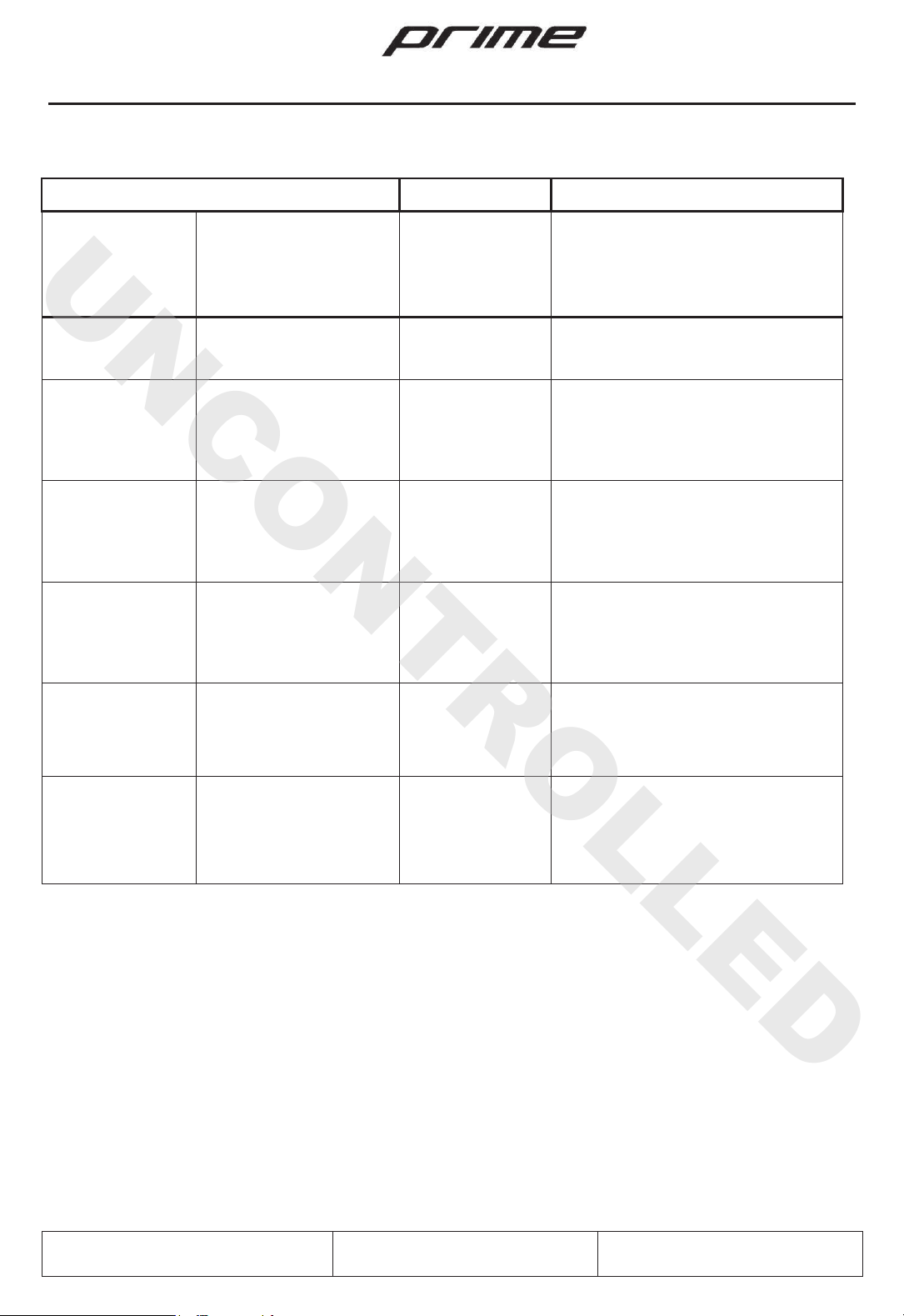
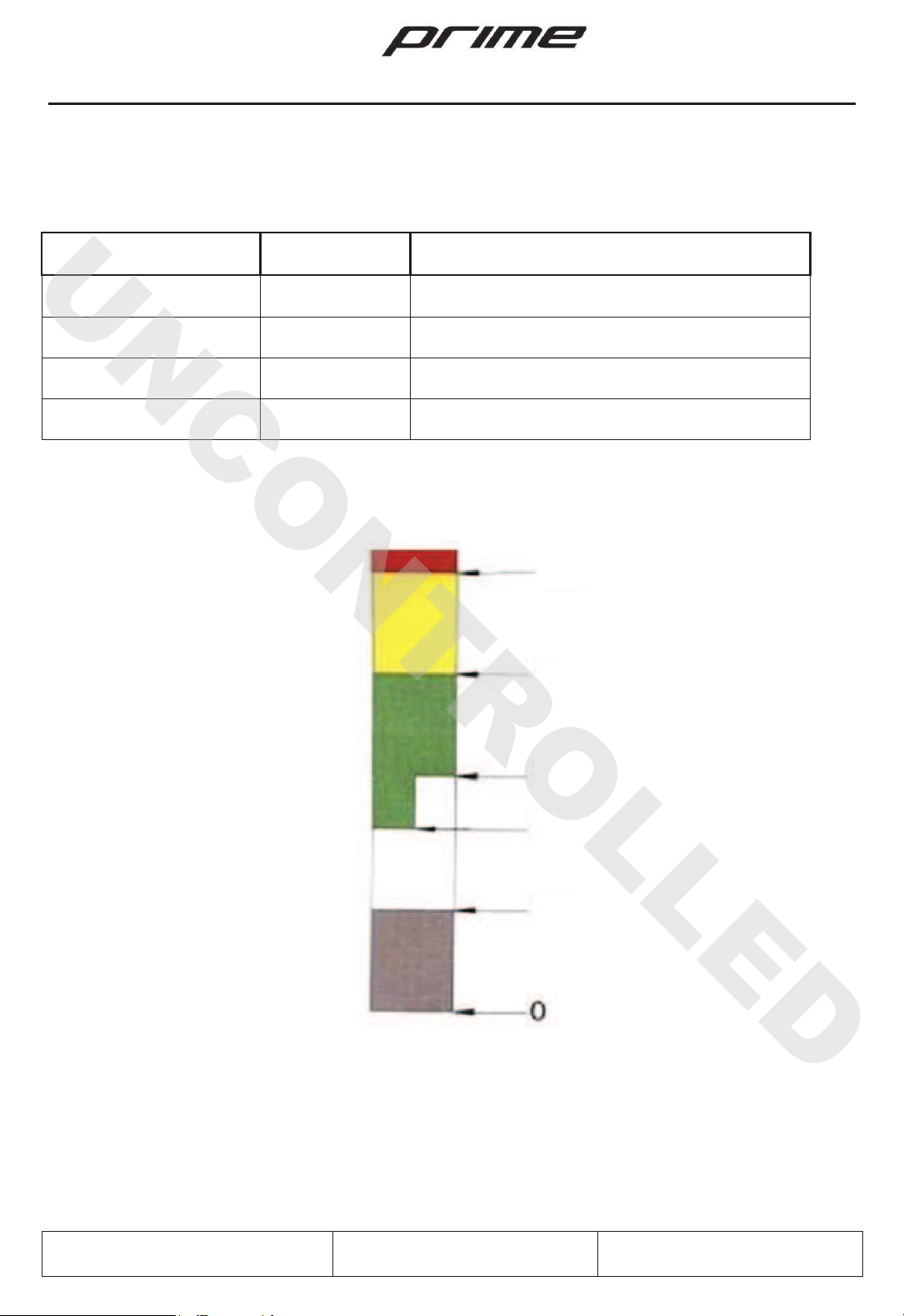
2.3. AIRSPEED INDICATOR MARKINGS
Airspeed limitations and their meaning of use are reported in the table below:
MARKING IAS Km/h
EXPLANATION
White arc
65-12
0 Km/h
Flap operating speed range
.
Green arc
80-250
Km/h
Normal operating range.
Yellow arc
250-300
Km/h
Maneuvers must be conducted with caution and
only in smooth air.
Red
line 305 Km/h
Maximum permissible speed for all operating
modes.
V1 = 65 km/h
V2 = 80 km/h
V3 = 120 km/h
V4 = 250 km/h
V5 = 305 km/h
UNCONTROLLED
165 kts
135 kts
65 kts
43 kts
35 kts

CF 300 –Flight Manual sect. 2 –Operating limitations
BY BLACKSHAPE
Document
n° BPU/FM003 Rev 3 dtd 03/06/2014 Page 18
-66
2.4. ENGINE LIMITATIONS
The following table shows the operating limitations of the engine installed on this aircraft. Please also
refer to the Operation Manual of the manufacturer Rotax Aircraft Engines.
ENGINE MANUFACTURER: BRP-Powertrain GmbH & Co KG
ENGINE MODEL: 912 ULS3
2.5. OPERATING LIMITATIONS
2.5.1. Engine
- Maximum Power Max T/O (5 min) 73,5 Kw (100 hp)
- Max RPM Max RPM T/O 5.800 rpm
- Maximum Continuous Power Max Power 69 Kw (93 hp) at 5500 rpm
- Maximum Continuous RPM Max RPM 5.500 rpm
2.5.2. Oil pressure
- Minimum under 3500 rpm 0.8 bar / 12 psi
- Normal up 3500 rpm 2.0 –5.0 bar / 29 –73 psi
- Maximum cold engine, short period 7.0 bar - 102 psi
2.5.3. Temperature
- Max cylinder head CHT 135°C
- Oil Min - Max 50°C –130°C
- Normal Operating Oil Temperature 90°C –110°C
- Max. exhaust gas temperature 880°C
2.5.4. Acceleration
Engine limitation in operations at 0 gravity and negative “G”
- Max 5 second at max. -0.5 G
UNCONTROLLED
CF 300 –Flight Manual sect. 2 –Operating limitations
BY BLACKSHAPE
Document
n° BPU/FM003 Rev 3 dtd 03/06/2014 Page 19
-66
2.5.5. Engine Start Operating Temperature
- Max + 50°C
- Min - 25°C
2.5.6. Fuel pressure
- Max 0.4 bar –5.8 psi
- Min 0.15 bar –2.2 psi
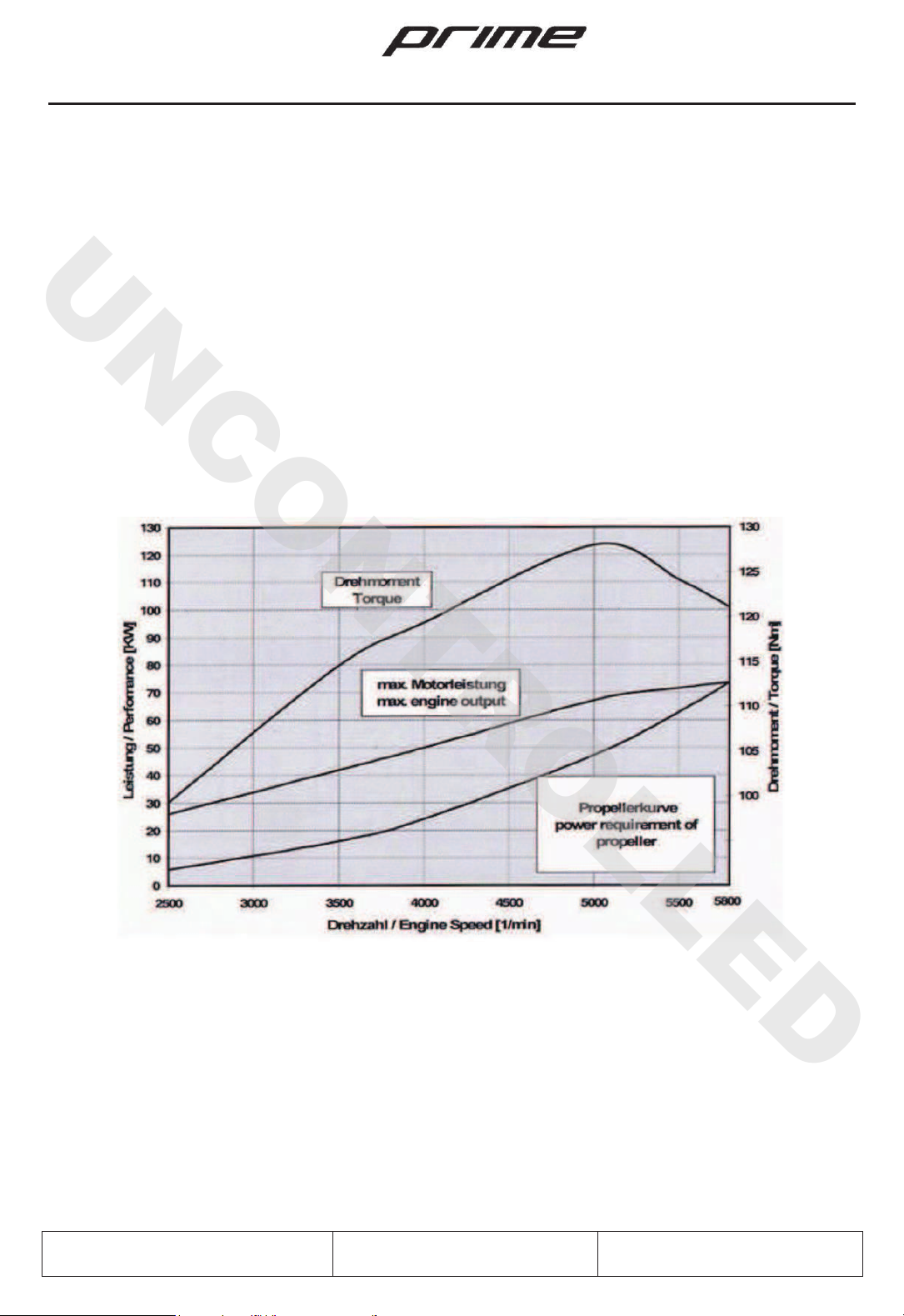
2.5.7. Performances graph in Standard Conditions (ISA)
Providing engine speed over 5500 rpm is restricted to 5 minutes
UNCONTROLLED
CF 300 –Flight Manual sect. 2 –Operating limitations
BY BLACKSHAPE
Document
n° BPU/FM003 Rev 3 dtd 03/06/2014 Page 20
-66
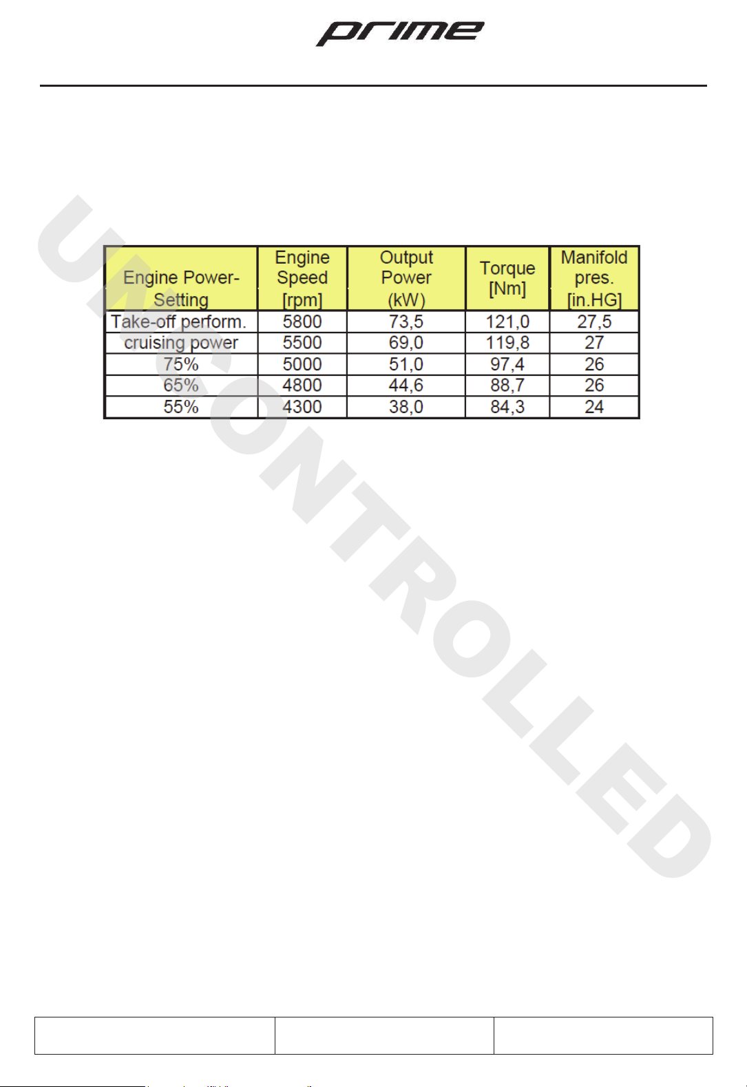
2.5.8. Engine performances table
The following table optimizes engine performances as a percentage of power settings compared to the
number of revolutions RPM:
2.5.9. Propeller
For technical data, proper installation and maintenance of the propeller, refer to the Operation
and Maintenance Manual of the manufacturer.
Manufacturer: MT Propeller
Model: MTV-33-1-A
Diameter: 1750 mm
Pitch: variable hydraulically
2.5.10. Lubricant –Coolant - Fuel
Data and Information contained in the Operation and Maintenance Manual of the
manufacturer must be considered.
Section 1.9.1 shows features and tables.
UNCONTROLLED
This manual suits for next models
1
Table of contents
Popular Aircraft manuals by other brands


FK-Lightplanes
FK-Lightplanes FK 14 B Pilot operating handbook

BOMBARDIER
BOMBARDIER CHALLENGER 604 Maintenance manual

Mooney
Mooney M20TN Service and maintenance manual

Advance acoustic
Advance acoustic EPSILON DLS Getting started

Cabrinha Kites
Cabrinha Kites Contra 2005 manual

Piper Aircraft Corporation
Piper Aircraft Corporation PA-28-181 Airplane Maintenance Manual

Cessna
Cessna 152 Information manual

Paratec
Paratec RDS Operational instructions

Alexander Schleicher
Alexander Schleicher AS 33 ES Flight manual

Sequoia
Sequoia F.8L Falco Flight manual

Flyitalia
Flyitalia MD-3 Rider Pilot's operating handbook and flight manual

Thoma Modelltechnik
Thoma Modelltechnik ORBIS 20'' Installation and operating manual