Blast DEFIANT 2 User manual

O
PERA T O RS
M
ANUAL
Defiant 2 Manual ƒ 5/31/05 5:44 PM Page 1

C
C
o
o
n
n
t
t
e
e
n
n
t
t
s
s
T
Ta
ab
bl
le
eo
of
f
S
S
a
a
f
f
e
e
t
t
y
y
Table of Contents
Section Page
Safety . . . . . . . . . . . . . . . . . . . . . . . . . . . . . . . . . . . . . . . . . . . . . . . . . . . . . . . . . . . . . . . . . . . .2
Warning . . . . . . . . . . . . . . . . . . . . . . . . . . . . . . . . . . . . . . . . . . . . . . . . . . . . . . . . . . . . . . . . . . .3
Warranty . . . . . . . . . . . . . . . . . . . . . . . . . . . . . . . . . . . . . . . . . . . . . . . . . . . . . . . . . . . . . . . .3
Operation . . . . . . . . . . . . . . . . . . . . . . . . . . . . . . . . . . . . . . . . . . . . . . . . . . . . . . . . . . . . . . .3
General Description . . . . . . . . . . . . . . . . . . . . . . . . . . . . . . . . . . . . . . . . . . . . . . . . . . . . . . .3
Introduction . . . . . . . . . . . . . . . . . . . . . . . . . . . . . . . . . . . . . . . . . . . . . . . . . . . . . . . . . . . . . . .4
Trigger Adjustment . . . . . . . . . . . . . . . . . . . . . . . . . . . . . . . . . . . . . . . . . . . . . . . . . . . . . . . .4
Barrel . . . . . . . . . . . . . . . . . . . . . . . . . . . . . . . . . . . . . . . . . . . . . . . . . . . . . . . . . . . . . . . . . .4
Specifications . . . . . . . . . . . . . . . . . . . . . . . . . . . . . . . . . . . . . . . . . . . . . . . . . . . . . . . . . . .4
Regulators . . . . . . . . . . . . . . . . . . . . . . . . . . . . . . . . . . . . . . . . . . . . . . . . . . . . . . . . . . . . . . .5
Ammunition Aspects . . . . . . . . . . . . . . . . . . . . . . . . . . . . . . . . . . . . . . . . . . . . . . . . . . . . . . .5
Hopper . . . . . . . . . . . . . . . . . . . . . . . . . . . . . . . . . . . . . . . . . . . . . . . . . . . . . . . . . . . . . . . .5
Paint . . . . . . . . . . . . . . . . . . . . . . . . . . . . . . . . . . . . . . . . . . . . . . . . . . . . . . . . . . . . . . . . . .5
Operation . . . . . . . . . . . . . . . . . . . . . . . . . . . . . . . . . . . . . . . . . . . . . . . . . . . . . . . . . . . . . . . . . .6
Gas Configurations . . . . . . . . . . . . . . . . . . . . . . . . . . . . . . . . . . . . . . . . . . . . . . . . . . . . . . .6
Electronics . . . . . . . . . . . . . . . . . . . . . . . . . . . . . . . . . . . . . . . . . . . . . . . . . . . . . . . . . . . . . . . .7
Battery Information . . . . . . . . . . . . . . . . . . . . . . . . . . . . . . . . . . . . . . . . . . . . . . . . . . . . . . .7
Anti Chop Eyes . . . . . . . . . . . . . . . . . . . . . . . . . . . . . . . . . . . . . . . . . . . . . . . . . . . . . . . . . .7
Board Operation . . . . . . . . . . . . . . . . . . . . . . . . . . . . . . . . . . . . . . . . . . . . . . . . . . . . . . . . . . . .8
Powering Up . . . . . . . . . . . . . . . . . . . . . . . . . . . . . . . . . . . . . . . . . . . . . . . . . . . . . . . . . . . .8
LED . . . . . . . . . . . . . . . . . . . . . . . . . . . . . . . . . . . . . . . . . . . . . . . . . . . . . . . . . . . . . . . . . . .8
Selecting Firing Modes . . . . . . . . . . . . . . . . . . . . . . . . . . . . . . . . . . . . . . . . . . . . . . . . . . . .8
Mode Selection . . . . . . . . . . . . . . . . . . . . . . . . . . . . . . . . . . . . . . . . . . . . . . . . . . . . . . . . . .9
Competition Lock . . . . . . . . . . . . . . . . . . . . . . . . . . . . . . . . . . . . . . . . . . . . . . . . . . . . . . .10
Assembly & Disassemly . . . . . . . . . . . . . . . . . . . . . . . . . . . . . . . . . . . . . . . . . . . . . . . . . . . . .11
Trigger Disassembly . . . . . . . . . . . . . . . . . . . . . . . . . . . . . . . . . . . . . . . . . . . . . . . . . . . . .11
Regulator Disassembly . . . . . . . . . . . . . . . . . . . . . . . . . . . . . . . . . . . . . . . . . . . . . . . . . . .13
Body Disassembly . . . . . . . . . . . . . . . . . . . . . . . . . . . . . . . . . . . . . . . . . . . . . . . . . . . . . . .15
Assembly Tips . . . . . . . . . . . . . . . . . . . . . . . . . . . . . . . . . . . . . . . . . . . . . . . . . . . . . . . . . .17
General Maintenance . . . . . . . . . . . . . . . . . . . . . . . . . . . . . . . . . . . . . . . . . . . . . . . . . . . . . . .18
Consumables . . . . . . . . . . . . . . . . . . . . . . . . . . . . . . . . . . . . . . . . . . . . . . . . . . . . . . . . . .18
Troubleshooting . . . . . . . . . . . . . . . . . . . . . . . . . . . . . . . . . . . . . . . . . . . . . . . . . . . . . . . . . . .19
Technical Specifications . . . . . . . . . . . . . . . . . . . . . . . . . . . . . . . . . . . . . . . . . . . . . . . . . . . .21
O-ring Specifications/Identification . . . . . . . . . . . . . . . . . . . . . . . . . . . . . . . . . . . . . . . .21
Screw Specifications/Identification . . . . . . . . . . . . . . . . . . . . . . . . . . . . . . . . . . . . . . . .23
Complete Parts List . . . . . . . . . . . . . . . . . . . . . . . . . . . . . . . . . . . . . . . . . . . . . . . . . . . . . . . .25
1
Safety
2
defiant
Congratulations on your purchase of the DEFIANT 2 Paintball Marker. The DEFIANT 2
represents the latest in Paintball Marker technology at a very affordable price. Before
operating your DEFIANT 2, please read the entire manual thoroughly.
W
WA
AR
RN
NI
IN
NG
G
This Paintball Marker is not a toy. Misuse or mishandling can result in serious injury or death. Every
person within range of a loaded Paintball Marker must wear eye protection specifically designed for
Paintball. Recommended at least 18 years of age to purchase, 14 years old to use with adult
supervision or 10 years old to use on Paintball fields meeting ASTM standards F1777-97. Be sure
to read the entire instruction manual before operating your DEFIANT 2.
S
SA
AF
FE
ET
TY
Y
Please follow all local, state, and federal laws concerning the operation and use of Paintball Markers.
By purchasing this Paintball Marker “YOU” assume all liability. B.L.A.S.T. assumes no liability for injury
or death due to misuse or mishandling of this Marker.
C
CA
AU
UT
TI
IO
ON
N
Never point a Paintball Marker at anyone not wearing Paintball-Approved goggles. Even at the lowest
possible operating velocity, a Paintball will cause serious injury should it hit someone in the eye area.
Never under any circumstances look down the barrel of your Marker. Even if wearing Paintball
approved goggles, you should Never look down the barrel.
Before performing any maintenance on the Marker, ensure air source is disconnected and
Marker has been degassed. Always ensure Marker is OFF whenever Marker is not operational.
Always insert barrel plug in barrel when Marker is not operational. Remove barrel plug only
in designated operational areas.
Only play at commercial playing fields that have a chronograph, referees, and clearly marked
safe areas. Chronograph your Marker before each game to ensure Marker is operating at a safe
velocity. Safe velocity is considered to be 280 feet per second (fps).
LLooookkssccaannkkiillll
LLooookkssccaannkkiillll
2
Defiant 2 Manual ƒ 5/31/05 5:44 PM Page 3

LLooookkssccaannkkiillll
LLooookkssccaannkkiillll
W
W
A
A
R
R
N
N
I
I
N
N
G
G
I
I
N
N
T
T
R
R
O
O
Introduction
2
defiant
Always ensure Marker is not shooting at a dangerous velocity. Ensure all participants
are wearing the proper Paintball safety equipment. You will be held liable if someone
is injured by a Paintball fired from your Marker regardless of fault.
WARRANTY
B.L.A.S.T. warrantees the DEFIANT 2 against damages in Manufacturing Defects only.
Electrical components are warranted for a period of 90 days. Solenoids are not warranted.
When utilizing after market Drop-Forwards ensure attachment bolts DO NOT protrude
into internal grip assembly. When utilizing aftermarket grips ensure attachment bolts
DO NOT protrude into internal grip assembly. Failure to do so may damage the internals
and will result in void of warranty. Use of Teflon tape will void warranty. Aftermarket
anodizing will result in void of warranty.
For questions concerning your
DEFIANT 2
manual please call (925) 625-7929.
OPERATION
The
DEFIANT 2
Marker is a solenoid controlled open-bolt design. The bolt is locked onto
a slotted bolt receiver that is attached to a dual pressurized machined slider (RAM),
and is controlled by the solenoid (An electronic 4-way valve control). The newly designed,
encapsulated ram sleeve features two chambers (one toward the front and one toward
the rear). The back of the chamber is pressurized to move the bolt forward, and the front
is pressurized to move the bolt backward. This allows for very low cycling pressure, as well
as much less cocking recoil.
GENERAL DESCRIPTION
The
DEFIANT 2
is a low pressure operating, open bolt, electronic Marker, featuring microchip
managed solenoid control, anti-chop eyes (ACE), dedicated low and high pressure regulators,
and unique patented pending modular ram sleeve.
The field strippable pull pin bolt is connected to a slotted bolt receiver that is attached to
a dual pressurized sliding ram. This ram is held within the encapsulated ram sleeve located
in the lower tube of the body. The low pressure regulator supplies air through the lower tube
of the body, through the valve, through the front barb, to the front barb of the solenoid. Upon
activation, the solenoid redirects alternating pressure through the rear barbs, from the
chamber in front of the ram to the back chamber behind the ram. The forward shifting ram
will then strike the poppet, opening the main valve which releases high pressure regulated
air up through the transfer port and into the upper tube of the body. The pull pin connected
bolt pushes the paintball into the breech while simultaneously redirecting the charge of air
to propel the projectile (paintball) to its target.
Warning
The DEFIANT 2 is controlled via the MEMBRANE PAD located on the rear of the Trigger Frame, as
well as the Dip Switch Control Panel located on the front side of the Frenzy Board. All of the
functions of the DEFIANT 2 can be easily accessed and changed by using both the Membrane
Pad and Dip Switch Panel.
GETTING STARTED
To power up your DEFIANT 2, Press the ON/OFF button. To turn off your DEFIANT 2, press and hold the
ON/OFF button for approximately 1 second until the LED turns Red and release. Buttons 1 and 2 allow
the user to change the Eye Sensor’s operational mode. Once powered up, pressing Button 1 will
change the Eye Sensor to Dry Fire Mode (also known as Simulation Mode), while Button 2 sets the
Eye Sensor to Delay Mode. Every DEFIANT 2 is equipped with a 3-Color, Light Emitting Diode (LED),
located on the side grip panel (left of the membrane pad)which allows the user to verify the current
Eye Sensor Mode and/or Battery Status. A detailed description of each function can be found in the
Board Operation section.
NOTE: The Frenzy Board IS NOT Programmable via the trigger.
TRIGGER ADJUSTMENT
The trigger is fully adjustable using the three screws within the trigger. The upper screw controls
the return spring tension, the center screw adjusts micro-switch activation point and the lower
screw adjusts the trigger stop point.
B
BA
AR
RR
RE
EL
L
The DEFIANT 2 comes standard with a one piece, .689 Bore, 12-inch Assassin barrel.
Barrel threads for the DEFIANT 2 are Auto-cocker type.
SPECIFICATIONS
Model . . . . . . . . . . . . . . . . . . . . . . . . . . . . . . . . . . . . . . . . . . . . . . . . . . . . . . . . . . .DEFIANT 2
Caliber . . . . . . . . . . . . . . . . . . . . . . . . . . . . . . . . . . . . . . . . . . . . . . . . . . . . . . . . . . . . . . . . 68
Action . . . . . . . . . . . . . . . . . . . . . . . . . . . . . . . . . . . . . . . . . . . . . . . . . . . .Electro-Pneumatic
Air Source . . . . . . . . . . . . . . . . . . . . . . . . . . . . . . . . . . . . . . . . . . .Compressed Air/Nitrogen
Battery Type . . . . . . . . . . . . . . . . . . . . . . . . . . . . . . . . . . . . . . . . . . . . . . . . . . .9-Volt Battery
Cycle Rate . . . . . . . . . . . . . . . . . . . . . . . . . . . . . . . . . . . . . .15bps Capped and/or Unlimited
Firing Modes . . . . . . . . . . . . . . . . . . . . . . . . . . . . . . . . . .Semi Auto and/or Ramping Modes
Effective Range . . . . . . . . . . . . . . . . . . . . . . . . . . . . . . . . . . . . . . . . . . . . . . . . . . . .150+ feet
Weight . . . . . . . . . . . . . . . . . . . . . . . . . . . . . . . . . . . .(With 12” Assassin Barrel) 2lbs., 1oz.
Length . . . . . . . . . . . . . . . . . . . . . . . . . . . . . . . . .(With 12” Assassin Barrel) 18.25 inches
Height . . . . . . . . . . . . . . . . . . . . . . . . . . . . . . . . . . . . . . . . . . . . . . . . . . . . . . . .7.875 inches
*Weight of Marker without 12” Assassin Barrel is 1lbs., 13oz.
43
*
Defiant 2 Manual ƒ 5/31/05 5:44 PM Page 5

I
I
N
N
T
T
R
R
O
O
O
O
P
P
E
E
R
R
A
A
T
T
I
I
O
O
N
N
Operation
Introduction continued
REGULATORS
Included with the DEFIANT 2 are 2 High-Flow Regulators. The Low Pressure Regulator (LPR)
uses a standard 1/8 inch hex key for adjustment, while the High Pressure Regulator (HPR)
uses a standard 3/16 inch hex key for adjustment. Turn the adjustment screw clockwise to
increase pressure and counter-clockwise to decrease pressure.
LOW PRESSURE REGULATOR
The low pressure regulator is mounted towards the front of the Marker under the barrel. It
controls the cycling pressure of the Marker. The ideal operating pressure should be between
85 – 95 PSI. NEVER EXCEED 100 PSI AS OVER-PRESSURIZING CAN DAMAGE SOLENOID. The
low pressure regulator is not used for velocity adjustments but for cycling pressures only.
HIGH PRESSURE REGULATOR
The high pressure regulator (also called the inline regulator) is the vertical regulator that screws
into the bottom of the ASA Receiver. All velocity adjustments are done with the High Pressure
Regulator. Typically, pressures vary from 200 PSI to 280 PSI depending on chronograph speed.
AMMUNITION ASPECTS
H O P P ER
The DEFIANT 2 requires a high feed rate of paintballs to make full use of its features.
To satisfy this need, the use of a motorized loader is recommended.
PAINT
Using top grade paint ensures the utmost in performance and accuracy.
GAS CONFIGURATIONS
Preset and Adjustable Tanks
A Compressed Air System also known as a Nitrogen Air System is the recommended propellant air
source for operating the DEFIANT 2. If you are using an Adjustable Tank the output pressure should
be set between 400 & 500 PSI, and Preset Tanks should be low pressure or 400 PSI output, however
a high pressure system is acceptable.
Co2
Co2 IS NOT the recommended propellant for the DEFIANT 2. You should only use a Compressed
Air System to operate your DEFIANT 2. When attaching air system hose fittings to your Marker,
DO NOT USE TEFLON TAPE. Use a thread sealant such as Loctite 545 instead.
GETTING STARTED
Maintenance for the DEFIANT 2 is very simple.
The Bolt should be lubricated sparingly with TRI-FLOW. Lubricating once a day or when dirty will
increase the life of the Ball Detents and also eliminate bolt drag.
The Ram or “Hammer” should be greased every 5000 shots with DOW 55. First degas your Marker.
Next, remove Bolt and Encapsulated Ram Sleeve Assembly, then remove the E-clip securing the
threaded Bolt Pin Receiver and Delrin Spacer and unscrew both. Next, unscrew the End Cap from
the Encapsulated Ram Sleeve and Ram will slide out of the rear of the Sleeve. Clean inside of Ram
Sleeve with a Q-tip and grease the internal O-ring located at the front end of the Ram Sleeve with
DOW 55, grease the Rear Ram O-ring and reassemble.
The Low Pressure Regulator Piston and the High-Pressure Regulator Piston O-rings should be greased
every 10,000 shots. Performing this simple maintenance will increase the life of the O-rings and keep
the Marker performing at the highest level possible.
NOTE: Always ensure Air Source is disconnected and Marker is fully degassed BEFORE performing
any/all maintenance, or when Marker is not operational.
65
2
defiant
Defiant 2 Manual ƒ 5/31/05 5:45 PM Page 7
2
defiant
W
W
a
a
r
r
n
n
i
i
n
n
g
g
BATTERY INFORMATION
The DEFIANT 2 uses a standard 9v battery. To change the battery, remove the Left Rubber Grip Panel,
then remove the 4 allen screws securing the two Trigger Frame halves. You’ll notice the battery
fits into the bottom of the grip frame. Disconnect the old battery and re-connect the new.
WARNING!
At this time it is good to verify screws are not protruding through the bottom of the grip and into the
interior components. Failure to do so may result in damage to the battery and/or Circuit Board.
ANTI- CHOP EYES (ACE)
The DEFIANT 2 incorporates a Break Beam, Anti-Chop Eye system, commonly referred to as
the ACE system. The ACE system consists of a set of sensors mounted near the bottom of
the breech to restrict firing until a ball is completely loaded into the breech. Always operate
the DEFIANT 2 with the eyes on. Failure to do so will more than likely result in broken paint
in the breech. The Transmitter Eye can be identified by the red and black wires and metal
casing. The Receiver Eye can be identified by it’s blue and black wires and black plastic casing.
Both Eyes run onto a single wiring harness. Always inspect ACE System wiring and harness
upon removal to ensure there is no damage present. If there is damage to either the wiring and/or
harness the Eyes should be replaced to ensure the ACE system does not fail during operation.
FACTORY SETTINGS
Standard factory FRENZY Board settings are as follows:
EYE . . . . . . . . . . . . . . . . . . . . . . . . . . . . . . .Forced
DEBOUNCE . . . . . . . . . . . . . . . . . . . . . . . . . . . 2ms
FIRING MODE . . . . . . . . . . . . . . . . . . . . .Semi-Auto
DWELL . . . . . . . . . . . . . . . . . . . . . . . . . . . . . . 8ms
A detailed description of each function is in the board operation section.
E
E
L
L
E
E
C
C
T
T
R
R
O
O
N
N
I
I
C
C
S
S
B
B
O
O
A
A
R
R
D
D
O
O
P
P
E
E
R
R
A
A
T
T
I
I
O
O
N
N
Board
Operation
Electronics
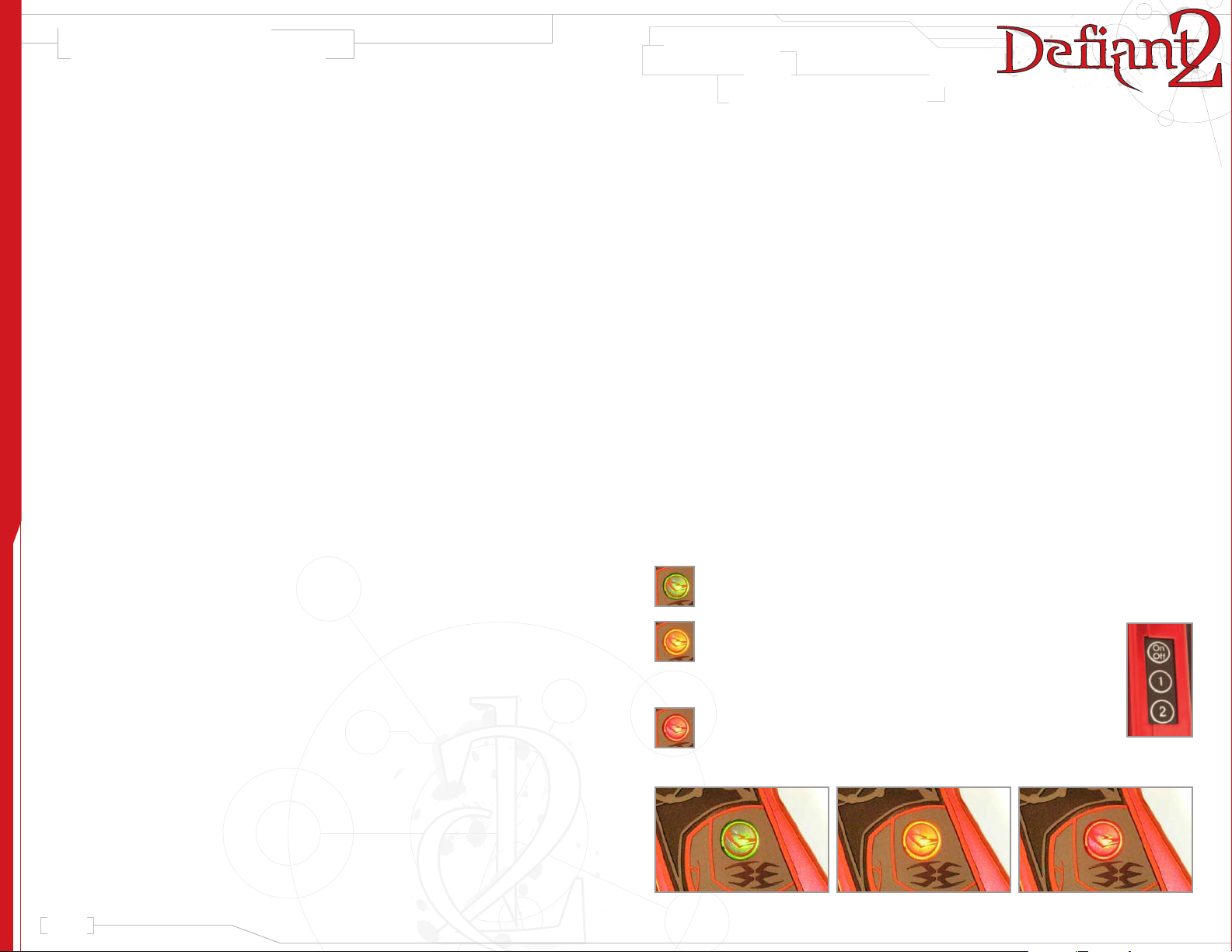
Normal Operation/FORCED Mode Eye Sensor Malfunction/DRY FIRE Mode Battery Low/Power OFF
123
Button Membrane
3
GETTING STARTED
Powering Up
1. To power up your DEFIANT 2, press the ON/OFF Button. A Green Flashing Light indicates Standard
Operation Mode. A more detailed description of Modes and their pertaining colors can be found below.
2. To turn off your DEFIANT 2, press and hold ON/OFF Button for approximately 1 second until the LED
turns Red, and Release. Your DEFIANT 2 is now OFF.
Light Emitting Diode (LED)
The DEFIANT 2 features a 3-Color LED that aluminates in either Green, Orange, or Red, and indicates the
operational Status of the Marker. Once the Marker is powered up the LED will flash Green and can be
seen through the Left Rubber Grip Panel. Upon Powering Up, the factory default Eye Sensor Mode is
FORCED/SEMI-AUTO and is indicated by the flashing Green LED. Pressing Button 1 will change the Eye
Sensor to DRY FIRE MODE, and is indicated by the flashing Orange LED. Pressing Button 2 will change the
Eye Sensor to DELAY MODE, however this function WILL NOT change the color of the LED. For example; If the
marker is set to FORCED and the LED is flashing Green, pressing Button 2 will change the Eye Sensor
to DELAY MODE and the LED will continue to flash Green. A Red flashing LED indicates LOW BATTERY.
NOTE: The LED will also flash Orange to indicate an Eye Sensor Malfunction.
SELECTING FIRING MODES
The DEFIANT 2 features 2 Firing Modes (Semi-Auto and Ramping)that are accessable via the Dip
Switch panel located on the front side of the Frenzy Board. See Figure “B” on the following page
1. GREEN LED Indicates Normal Operation for Both Modes (Semi-Auto and Ramping).
Upon Power-Up the Eye Sensor setting will always default to FORCED, regardless of Mode.
2. ORANGE LED Indicates EYE SENSOR MALFUNCTION and/or DRYFIRE Mode.
(DRY FIRE Mode Formerly known as SIMULATION Mode, Demonstrates how
the Marker should operate with an appropriate supply of paintballs and fully
charged air system.)
3. RED LED Indicates LOW BATTERY and/or Powering OFF.
Below are views of each LED Color as well as the corresponding description(s)for each.
87
Defiant 2 Manual ƒ 5/31/05 5:45 PM Page 9
2
defiant
B
B
O
O
A
A
R
R
D
D
O
O
P
P
E
E
R
R
A
A
T
T
I
I
O
O
N
N
I
I
N
N
T
T
R
R
O
O
Competition
Lock
Board Operation
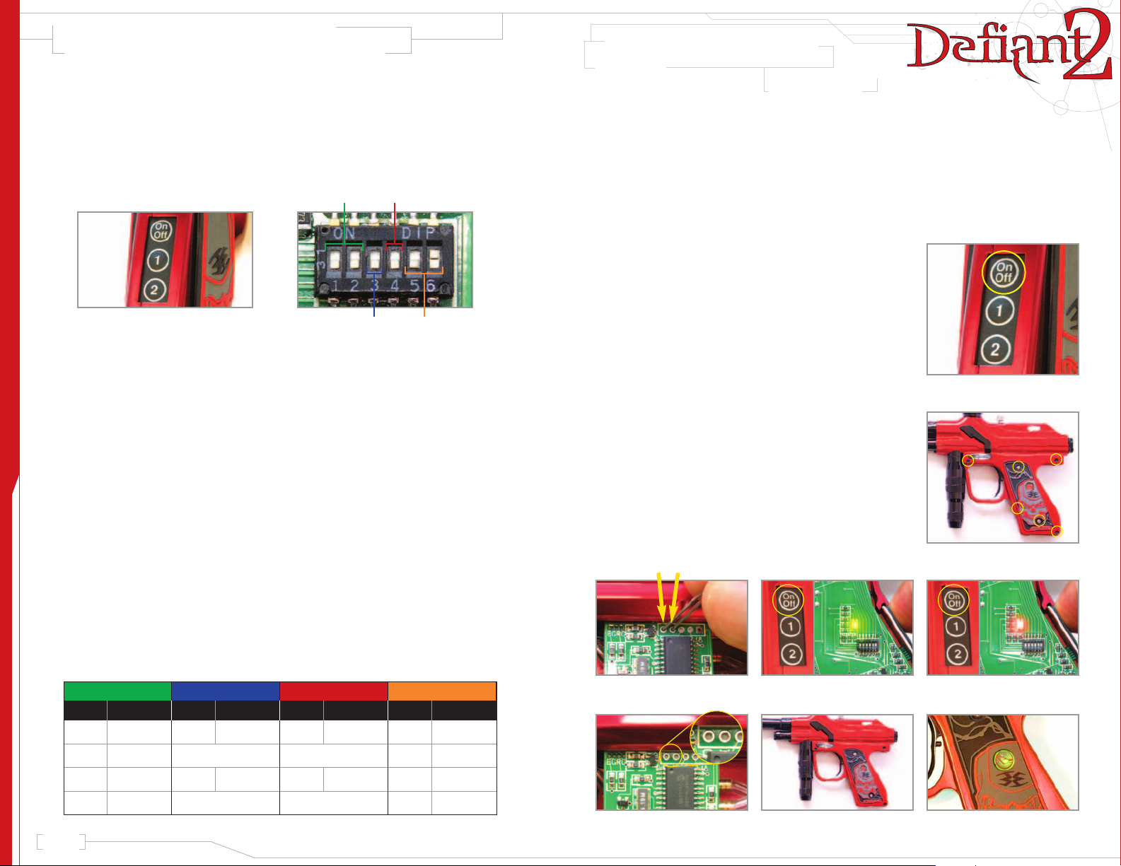
MODE SELECTION (Version 127.4T FRENZY only)
The LED FRENZY Board is driven via the Two-Button Membrane Pad on the rear of the Trigger Frame
(figure “A”) as well as the On-Board Dip Switch Panel (figure “B”) located on the front side of the Fenzy
Board and is accessed by removing the left trigger frame panel. Dip Switches 1 and 2 control DEBOUNCE,
Dip Switch 3 controls CAPPED MODE, Dip Switch 4 controls FIRING MODE, and Dip Switches 5 and 6 control
DWELL. Below are descriptions of the different modes and how they affect the Marker’s performance.
EYE - Upon Powering up, the DEFIANT 2’s ACE System will always default to FORCED MODE. Pressing
Button 1 will Deactivate the ACE System and the marker will resume operation utilizing the
currrently selected Firing Mode, in DRY FIRE MODE. Pressing Button 2 will change the current
ACE System Setting to DELAY MODE. Listed below are descriptions of each ACE System Setting.
FORCED - Marker fires only when ball is present at time of trigger pull.
DELAY - Marker fires when ball is present at time of trigger pull and if a ball IS NOT
present the Marker will wait 1 second before firing.
DRY FIRE - ACE System is Bypassed (OFF)and Marker fires at time of trigger pull.
DEBOUNCE - Determines (in milli seconds) how long after each trigger pull, the board will ignore
further trigger activity. (see figure “C” for details)
CAPPED MODE - Determines if marker operates at an unlimited rate of fire or under a 15bps Cap.
FIRING MODE - Determines which Firing Mode is selected. (see figure “C” for details)
DWELL - Determines how long the bolt remains in the forward position before repeating cycle.
Changing Dip Switch Settings is very simple. Sliding Switches UP sets them to the ON position,
while Sliding Switches DOWN sets them to the OFF position. A small paper clip works well for
toggling Dip Switches. The chart below illustrates how the Dip Switch Panel affects the settings.
Dindicates DOWN, while Uindicates UP.
COMPETITION LOCK - With Competition Lock ON, Dwell and Debounce settings are locked and
cannot be changed until Competition Lock is DISABLED. While in Competition Mode the Eye Sensor
setting can be changed as normal to Dry Fire Mode or Delay Mode. When Competition Lock is
active, the LED will aluminate Green as normal upon powering up. (Marker is not BPS capped
while using competition Lock)
ACTIVATING COMPETITION LOCK:
1. Turn Marker OFF.
2. Open up Trigger Frame to gain access to the Circuit Board.
3. Short out Cand DTerminals (holes)at the top of the board.
Paper clips work well for this. Bend the clip so that one
end is touching the Dand the other end is touching C.
4. Turn Marker ON.
5. Turn Marker OFF.
6. Disconnect the Dand Cshort and leave off
for at least 30 seconds.
7. Reassemble Trigger Frame.
8. Ready to use with COMPETITION LOCK.
To turn OFF Competition Lock follow the same procedure.
When Competition Lock is active the marker will only operate
in Semi-Auto Mode and Ramping Mode will be disabled.
For information and instructions regarding previous and/or
future versions of the FRENZY Board (Other than version 127.4T),
please refer to separate instructions sheet included in box.
Turn Marker OFF
Membrane Pad
1
Open Trigger Frame
2
Disconnect Short, Leave OFF Reassemble Trigger Frame COMPETITION LOCK
678
Short out C and D Terminals Turn ON Comp Lock ON
345
Turn OFF
Terminals
C D
continued
109
DEBOUNCE FIRING MODES
DWELL
CAP MODES
Dip Switch Panel
BA
DEBOUNCE
[1][2]RESULT
D D 2mS
D U 5mS
UD 15mS
DD 50mS
CAP MODE
[3]RESULT
UCAPPED
D UNCAPPED
FIRING MODE
[4]RESULT
URAMP MODE
D SEMI-AUTO
DWELL
[5][6]RESULT
D D 6mS
DU8mS
UD 10mS
DD 12mS
*
**
*
NOTE: (****)Indicates the Factory Default Setting
While in CAPPED Mode the Marker
will be limited to a 15bps limit.
While UNCAPPED the Marker will
operate at an unlimited Rate of fire.
RAMPING will comense after 4 rapid
trigger pulls in succession.
While in SEMI-AUTO MODE the Marker
will fire one shot per trigger pull.
figure C
Defiant 2 Manual ƒ 5/31/05 5:45 PM Page 11

2
defiant
A
A
S
S
S
S
E
E
M
M
B
B
L
L
Y
Y
&
&
D
D
I
I
S
S
A
A
S
S
S
S
E
E
M
M
B
B
L
L
Y
Y
Assembly&Disassembly
GETTING STARTED
WHEN DISASSEMBLING THE DEFIANT 2 ALWAYS ENSURE THE MARKER IS DEGASSED.
The DISASSEMBLY portion of this manual will be divided into three sections.
I. Trigger Frame Disassembly
II. Regulator Disassembly
III. Body Disassembly
NOTE: When ASSEMBLING the DEFIANT 2, perform the entire disassembly
process in reverse order.
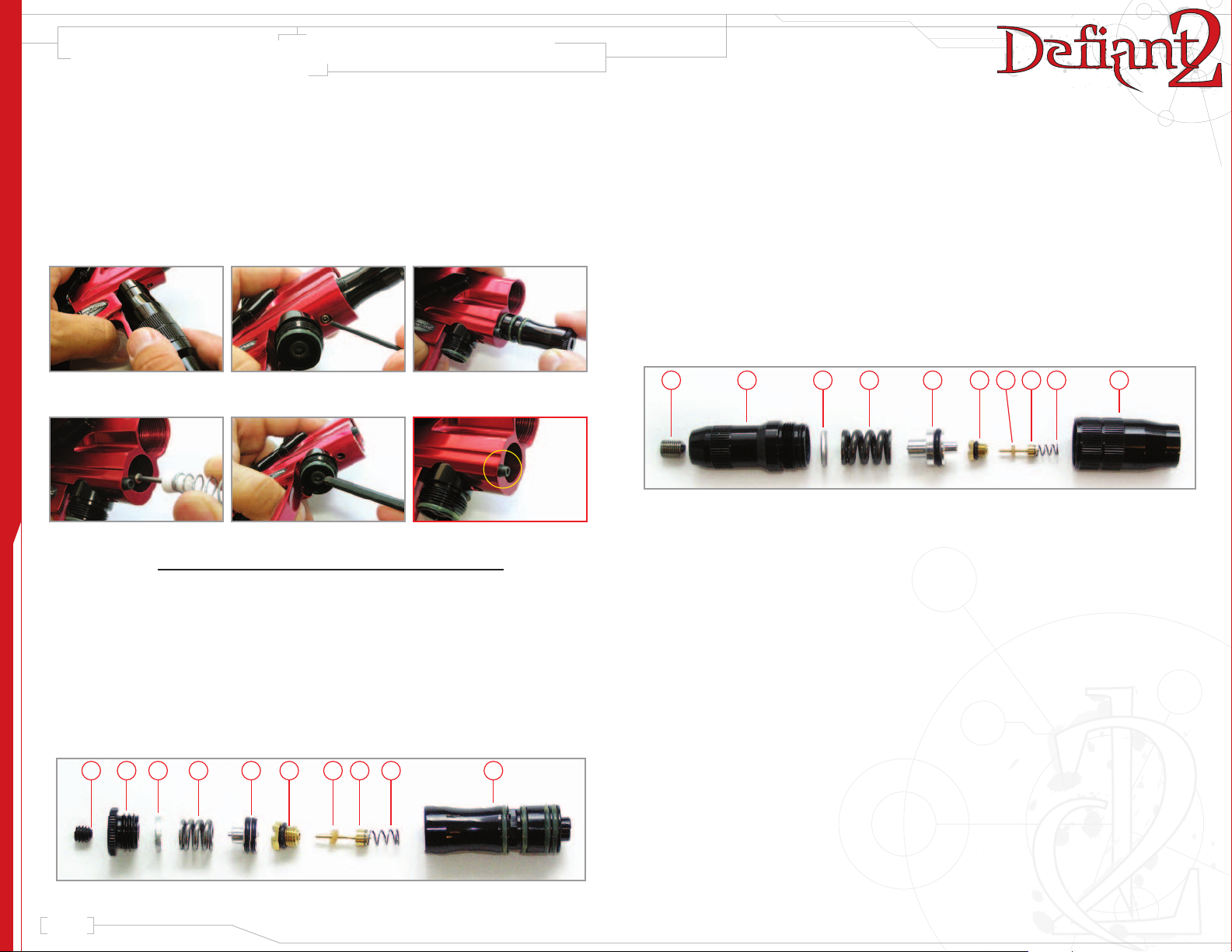
I. TRIGGER FRAME DISASSEMBLY
1. Remove left side LED Grip.
2. Remove 4 allens to separate Trigger Frame Halves, exposing circuit board.
3. Disconnect Battery.
4. Remove 2 Board retaining screws. (1-1/16 Allen Head screw and 1-Phillips Head screw)
5. Flip Board over towards left side to expose wiring..
6. Lift up on black LCD ribbon locks located on each side of membrane ribbon harness and
remove complete membrane assembly from trigger frame.
7. Remove Battery and Solenoid Harness.
I. TRIGGER FRAME DISASSEMBLY (continued)
8. Remove Eye Sensor Wire Harness.
9. Remove Circuit Board.
10. Remove Shouldered Trigger Retaining Screw and lift out Trigger and Trigger Return Spring.
11. Loosen Front Frame Retaining Screw.
12. Remove Rear Frame Retaining Screw.
13. Lift Out Front Hose from Around Hose Guard. (A small allen wrench works well)
14. Slide Trigger Frame Back from Body.
15. Remove Trigger Frame.
16. Diconnect Solenoid from Body.
NOTE: Use care when removing airlines.
Always inspect hoses after removal to ensure no tears or damage occurred during removal.
Flip Board To Expose Wiring Lift Up LCD Ribbon Locks Remove Battery/Solenoid Harness
Separate Trigger Halves Disconnect Battery Remove Board Retaining Screws
WARNING!
Ensure Air Source is disconnected and Marker
is discharged before making any mechanical
adjustments to Marker internals or electronics.
Slide Frame Back From Body Remove Trigger Frame Remove Solenoid From Body
Loosen Front Frame Retaining Screw Remove Rear Frame Retaining Screw Lift Hose From Around Hose Guard
Remove TriggerRemove Board
Remove Eye Harness
234
7
56
Grip Removal
18
13
16
12
15
11
14
910
1211
Defiant 2 Manual ƒ 5/31/05 5:46 PM Page 13
A
A
S
S
S
S
E
E
M
M
B
B
L
L
Y
Y
&
&
D
D
I
I
S
S
A
A
S
S
S
S
E
E
M
M
B
B
L
L
Y
Y
Assembly&Disassembly
REGULATOR DISASSEMBLY (continued)
HIGH-PRESSURE REGULATOR (HPR)
1. Unscrew Allen Adjuster.
2. Unscrew Lower End of (HPR)
High-Pressure Regulator Housing.
3. Remove Regulator Spring Washer.
4. Remove Regulator Spring.
5. Remove Piston.
NOTE: At this time the Regulators are disassembled. Listed below are key elements to
remember during assembly.
1. Piston: Ensure cupped end of Piston is facing towards Pin Valve.
2. Pin Valve: Ensure Pin Valve is not bent and seats in cupped end of Piston.
Failure to do so will cause Regulators to function improperly.
3. Air Barb: Ensure fiber washer is on Air Barb base when installing.
This will ensure Air Barb does not leak.
4. Poppet Spring Attachment: Ensure small end of Spring sits firmly on Poppet.
5. ASA Receiver: Place small portion of Loctite on Retaining Allen when installing.
This will ensure ASA Receiver does not work itself loose during operation.
4. LPR Retaining Screw: Place small portion of Loctite on Retaining Allen when installing.
This will ensure LPR (Low-Pressure Regulator)does not work itself loose during operation.
6. Remove Pin Valve Retainer.
7. Remove Teflon Washer.
8. Remove Pin Valve.
9. Remove Spring from Upper Reg. Housing.
10. Upper End of (HPR)High-Pressure
10. Regulator Housing.
Torpedo/High-Pressure Regulator
LOW-PRESSURE REGULATOR (LPR)
1. Unscrew Allen Adjuster.
2. Unscrew LPR End Cap (Part 2)from
Low-Pressure Regulator Base (Part 10).
3. Remove Regulator Spring Washer.
4. Remove Regulator Spring.
5. Remove Piston.
Low-Pressure Regulator
3 54 86 7 9 101 2
743 85 6 9 101 2
II. REGULATOR DISASSEMBLY
1. Remove High-Pressure Regulator to gain
proper clearance to the LPR Retaining Screw.
2. Remove LPR Retaining Screw from Body.
3. Slide LPR Assembly from Body.
Remove Spring and Poppet Remove ASA Retaining Screw Transfer Hole Screw
4
Remove HPR
1
5
Remove LPR Retaining Screw
2
6
Slide LPR Assembly from Body
3
2
defiant
6. Remove Pin Valve Retainer.
7. Remove Teflon Washer.
8. Remove Pin Valve.
9. Remove Spring from Upper Reg. Housing.
10. Low-Pressure Regulator Housing/LPR Base.
4. Remove Spring and Poppet Assembly.
5. Remove ASA Receiver Retaining Screw.
6. NOTE: The Transfer Hole Screw will only need to
be removed if a leak is detected, or a great deal
of debris is present.
1413
Defiant 2 Manual ƒ 5/31/05 5:46 PM Page 15
A
A
S
S
S
S
E
E
M
M
B
B
L
L
Y
Y
&
&
D
D
I
I
S
S
A
A
S
S
S
S
E
E
M
M
B
B
L
L
Y
Y
Assembly&Disassembly
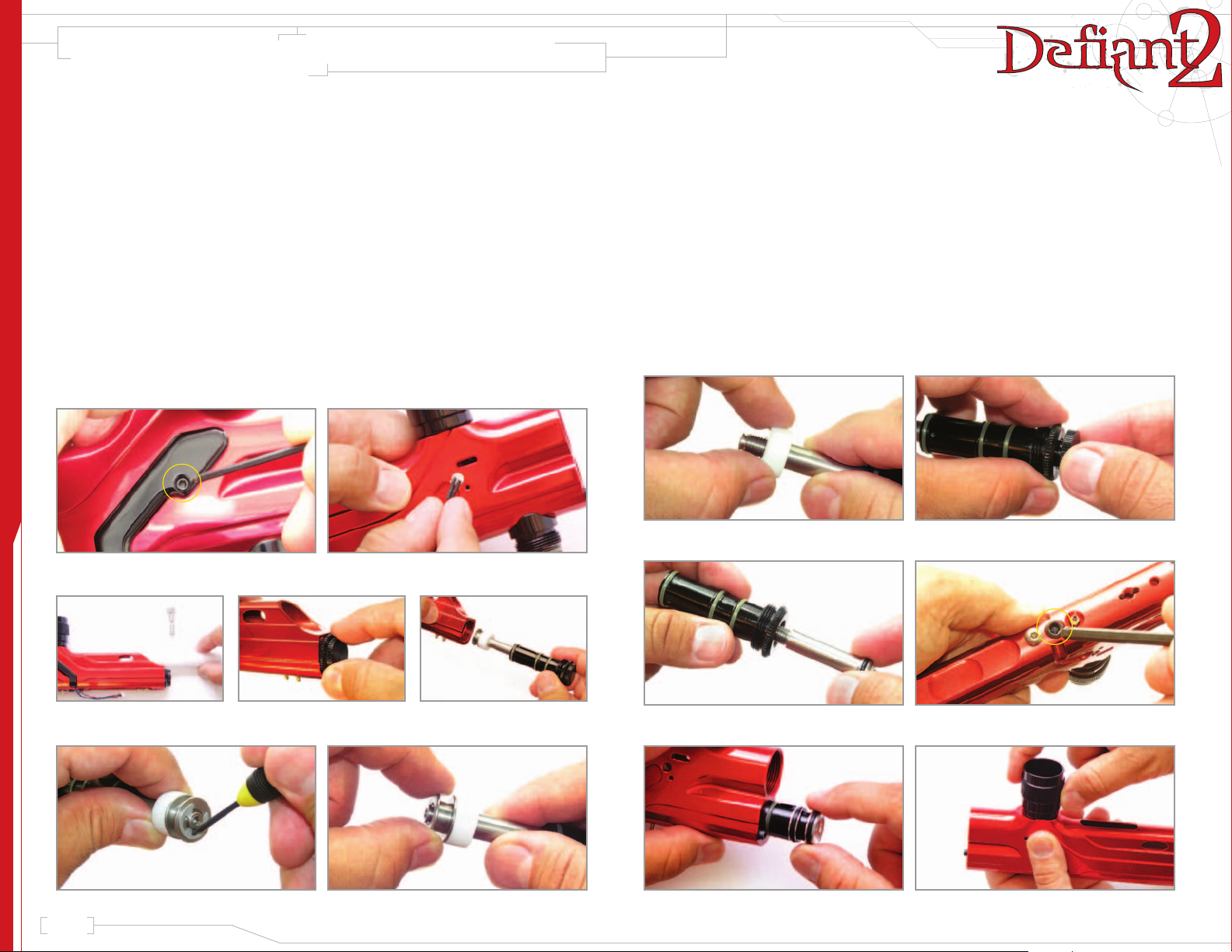
BODY DISASSEMBLY (continued)
9. Tilt front end of Encapsulated Ram Sleeve Up, and allow ram to slide out from rear.
NOTE: BEFORE reinserting the Ram, be sure to clean the inside of the ram sleeve
with a Q-tip and inspect the internal O-ring located toward the front of the Ram Sleeve.
Check for excessive wear and/or damage. If the O-ring needs to be replaced,
carefully remove it using a dental pick or the like, and replace. Be sure to lubricate
the internal O-ring with Dow 55 before reinserting Ram.
10. Turn Body over to expose bottom of marker body and remove Valve Retaining Screw.
11. Remove the Valve through front end of the Marker Body.
(Gently push the Valve from the rear with a barrel swab)
12. Remove Feedneck from Body.
NOTE: At this time the Body is disassembled. Listed on the following page are key points to remember during assembly.
III. BODY DISASSEMBLY
First: Ensure Barrel of Marker is removed.
a1. Remove both Eye Sensor Covers (one on each side) by removing Retaining Screw.
a2. Remove both Eye Sensors (one on each side) by carefully pulling sensor heads from mounting holes.
a3. Lift up on Bolt Retaining Pin and slide Bolt out of rear of Marker.
4a. Unscrew Encapsulated Ram Sleeve Assembly from Marker Body. (turn counter-clockwise)
4b. Remove Encapsulated Ram Sleeve Assembly by sliding it out from rear of Marker Body.
a5. Remove E-clip from front of Ram.
a6. Remove Slotted Bolt Pin Receiver. (turn counter-clockwise)
a7. Remove Delrin Bolt Pin Receiver Spacer. (turn counter-clockwise)
a8. Unscrew Ram Sleeve End Cap from Ram Sleeve.
Remove Eye Sensor Covers
1
Remove Eye Sensors
2
Remove E-clip from Front of Ram
5
Remove Slotted Bolt Pin Receiver
6
Remove End Cap from Ram Sleeve
8
Tilt Ram Sleeve Up and Remove Ram from Rear
9
Remove Valve through Front
Remove Valve Retaining Screw
10
11
Remove Feedneck from Body
12
Lift Bolt Pin and Remove Bolt Unscrew Ram Sleeve Remove Ram Sleeve Assembly
34a. 4b.
Remove Delrin Bolt Pin Receiver Spacer
7
2
defiant
1615
Defiant 2 Manual ƒ 5/31/05 5:47 PM Page 17

A
A
S
S
S
S
E
E
M
M
B
B
L
L
Y
Y
&
&
D
D
I
I
S
S
A
A
S
S
S
S
E
E
M
M
B
B
L
L
Y
Y
Assembly&Disassembly
ASSEMBLY TIPS
KEY ELEMENTS TO REMEMBER DURING ASSEMBLY.
O-Rings: LUBRICATE ALL O-RINGS UPON INSTALLATION.
Ram Sleeve O-rings: Always ensure all O-Rings are in good condition upon installation.
Air Barb: Ensure fiber washer is on Air Barb base prior to installation. This will ensure a proper seal.
LPR Retaining Allen: Use small amount of Loctite on LPR Retaining Allen when installing.
Failure to do so may result in LPR sliding off the Marker Body, causing extreme damage to
the Marker and/or possibly injuring the operator and others. A firm snug is all that is required
to maintain a secure fit.
Poppet installation: Before installation, inspect Poppet thoroughly. If Poppet shows signs of
excessive wear, it must be replaced in order to ensure a proper seal. Allow Poppet to slide into
the Valve when installing. Once seated, tap on Poppet end to mate Poppet with Valve. Ensure
small end of spring seats firmly on Poppet.
Valve Retaining Allen: Use small amount of Loctite on Valve Retaining Allen when installing.
Failure to do so may result in Valve sliding within the Marker Body, causing extreme damage
to the Marker and/or possibly injuring the operator.
Eye Sensor Harness: Ensure Harness is seated in grove provided before attaching Eye Covers.
Failure to do so may result in pinched wires and render the eyes inoperable.
Eye Covers: Ensure Ball Detents remain aligned and in Covers upon install. Do not over tighten
the cover screws. A firm snug is all that is required to maintain a secure fit.
Feedneck: Removal of the Feedneck may require the use of a Strap Wrench since it is firmly
attached during initial assembly. Simply wrap the Strap around the Feedneck and turn counter-
clockwise. To Reinstall simply screw the Feednack back onto the body and tighten firmly using
a Strap Wrench.
NOTE: Once Marker is completely disassembled, carefully inspect all Screws, O-Rings, Ball Detents,
Air Barbs, Hoses, Eye Sensors, Wiring, Electronics, Battery, Regulators, and Feedneck Threads,
etc., for signs of premature or excessive wear, stripping and/or damage.
If ANY parts show signs of premature or excessive wear, stripping and/or damage, and you need
to order them, please refer to the chart on the facing page for reference. A more detailed
description of parts and/or the corresponding PART NUMBER(S)can be found in the COMPLETE
PARTS CHECKLIST located on the inside back cover of the manual. Simply call B.L.A.S.T. at the
number provided and a Customer Service Representative will assist you.
*PLEASE HAVE PART NUMBER(S)READY WHEN CALLING.
GENERAL MAINTENANCE
WARNING: NEVER use lightweight gun oil on Marker. Oil will destroy internals of Air Valve and O-rings.
Keep foreign obstructions out of Marker internals and Lubricate all O-rings within the Marker with a
generous coat of Dow 55 Lubricant. The Ram requires Lubing every 5,000 rds. fired. Regulator
O-rings should be Lubed every 10,000 rds. fired. Failure to do so will reduce recovery time of
Regulators. Additionally, the Piston will wear a groove in the Regulator housing. Ensure the Pin
Valve lines up with the Cupped End on the Piston during reassembly. This will eliminate the
inadvertent bending of the pin.
Below is a list of the most common Consumable Components of the DEFIANT 2.
CONSUMABLE COMPONENTS
COMPONENT QUANTITY SIZE
Body Assembly
Ram Front O-ring (Inside Front of Sleeve)1012
Ram Rear O-ring 1011
Ram Rear Bumper O-ring (Teflon)1006
Pressurized Ram Sleeve O-ring 3015
Sleeve End Cap O-ring 2011
Regulator Assembly
HPR Housing O-ring 1016
HPR Piston O-ring 1113
HPR Pin Valve Base Washer 1010
HPR Pin Valve Washer (Teflon)1006
LPR Piston O-ring 2011
LPR Pin Valve Base 1010
LPR Pin Valve Washer (Teflon)1006
ASA Receiver Mounting O-ring 1113
Trigger Assembly
Airline 1 to front of body 5.0 in.
Airline 1 to middle of body 5.0 in.
Airline 1 to rear of body 2.5 in.
Circuit Board 1004
2
defiant
1817
Defiant 2 Manual ƒ 5/31/05 5:47 PM Page 19
T
TR
RO
OU
UB
BL
LE
ES
SH
HO
OO
OT
TI
IN
NG
G
T
T
R
R
O
O
U
U
B
B
L
L
E
E
S
S
H
H
O
O
O
O
T
T
I
I
N
N
G
G
Troubleshooting
NOTE: Refer to Assembly/Disassembly to perform repairs indicated below.
1. Replace Poppet
2. Replace Ram Sleeve O-rings
1. Open Trigger Frame and
reconnect Hose
2. Tighten or Replace Air Barb
1. Check LPR Pressure. It should
be between 85-95 PSI.
2. It is not recommended to
disassemble Solenoid.
Call B.L.A.S.T. for assistance
1. Check Dwell and Reset to Factory
Settings Via Dip Switch Panel
2. Turn in LPR Set Screw. Pressure
should be between 85-95 PSI.
3. Open Frame and check hoses
4. Push Reset Button on Solenoid
when Marker is pressurized. If
Marker does not fire call B.L.A.S.T.
6. Open Trigger Frame and check
Solenoid connection/Wiring
1. Lube Piston with DOW 55
2. Check Dwell and set to
Factory Settings
3. Replace 011 O-Ring
4. Check pressure and
reset to 85-95 PSI
5. Use appropriate size
paintball.
1. Poppet is not sealing
2. Ram Sleeve O-rings
are damaged
1. Air Hose has become
disconnected
2. Hose Barb has come loose
or is broken
1. Marker is over pressurized
2. Foreign material has lodged
inside Solenoid
1. Dwell is to low
2. LPR too low
3. Pinched Hose
4. Debris in Solenoid
5. Check the LED.
If LED is not Flashing at time of
Trigger Pull it is the Micro-Switch
6. If LED is Flashing it is
possible the Solenoid connector
is disconnected or damaged
1 .High Pressure Regulator
Piston is dry
2 .Dwell too low
3. Large Ram O-ring (011) is worn.
4. LPR Pressure too low
5. Paint does not fit Barrel
Marker leaks down Barrel
Marker leaks from inside
Trigger Frame
Marker leaks from Solenoid
Marker is pressurized and
will not fire
Inconsistent Velocity
1. Replace O-rings
2. Replace Regulator Seat
3. Tighten Brass Nut
4. Replace O-ring
1. Check Dwell and reset
to Factory Settings
2. Check output pressure of
High-Pressure Regulator
1. Check depth of Pin Valve
2. Raise LPR pressure
1. Check and make sure Eyes
are ON and/or operational
2. Replace Ball Detents
3. Size paint for Barrel
4. Use winter-fill paint in
winter or heat your paint
1. Check Eye Alignment
2. Clean Eyes
3. Open and inspect Eye Wires
and Harness
4. Replace Bad Eye(s)
1. Call B.L.A.S.T.
for assistance
1. LPR Base 0-rings are bad
2. Regulator Seat is bad
3. Brass Nut isn’t tight enough
4. 010 0-ring on Brass
Nut is worn or damaged
1. Low dwell
2. High-Pressure Regulator spiking
over pressurizing valve chamber
1. Preset tank pin valve is
depressed too far or not enough,
starving Marker of air
2. LPR pressure too low
1. Eyes are turned off
and/or damaged
2. Missing or worn ball detents
3. Paint too large for barrel
4. Using brittle paint in
cold weather
1. Eyes misaligned
2. Dirty Eyes
3. Pinched or cut wires
4. Bad Eye(s)
1. Faulty Micro-Switch
LPR spikes
Marker fires with low
first shot
Marker dies off with
rapid fire
Marker is Breaking paint
Eyes fail when in delay
Marker fires on pull
and release
2
defiant
2019
PROBLEM DIAGNOSIS REPAIR PROBLEM DIAGNOSIS REPAIR
Defiant 2 Manual ƒ 5/31/05 5:47 PM Page 21
T
T
E
E
C
C
H
H
N
N
I
I
C
C
A
A
L
L
.
.
.
.
.
.
S
S
P
P
E
E
C
C
S
S
Technical
Specifications
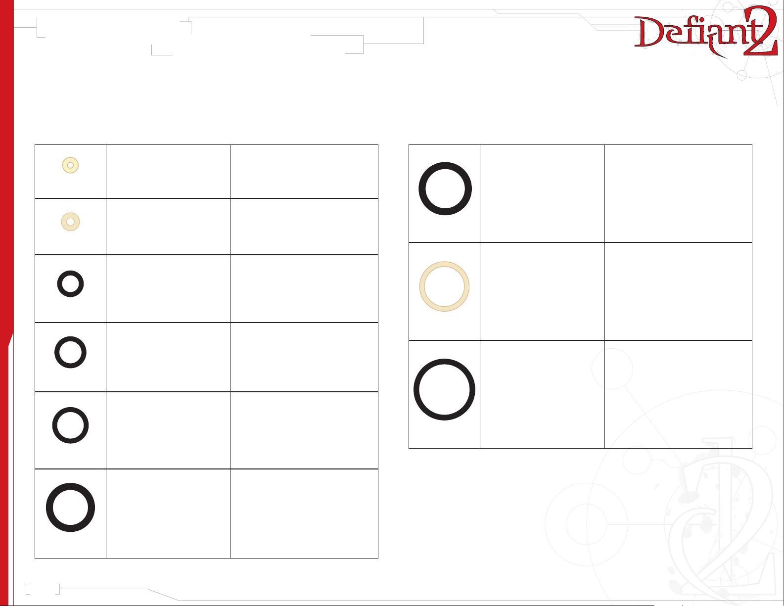
PARTS IDENTIFICATION
O-ring Sizer/Identifier
O-ring & Size Quantity Discription/Breakdown
Teflon Regulator Seat Washer2 Per Marker
006 (Polyurethane)
Ram Bumper O-ring1 Per Marker
006 (Teflon)
Brass Nut O-ring for
Low-Pressure Regulator &
High-Pressure Regulator (1 each)
2 Per Marker
1 - Ram REAR
2 - Ram Sleeve Cap
2 - LPR Piston
(Low-Pressure Regulator)
5 Per Marker
010
011
FRONT Ram O-ring
(Inside Front of Ram Sleeve)
1 Per Marker
012
FRONT Valve O-rings2 Per Marker
112
O-ring & Size Quantity Discription/Breakdown
4 - LPR Housing O-rings
3 - Encapsulated Ram Sleeve O-rings
1 - Valve Base O-ring
1 - ASA Thread Base O-ring
9 Per Marker
015
HPR Lower End O-ring1 Per Marker
118
1 - ASA Receiver Mounting O-Ring
1 - HPR Piston O-ring
(High-Pressure Regulator)
2 Per Marker
113
NOTE: The number below each O-ring on the left column indicates the size of the O-ring.
For instance if you need to purchase a Ram Bumper O-ring, you would ask for an O-ring size 006 Teflon.
2
defiant
2221
NOTE: O-rings are shown in actual size.
Defiant 2 Manual ƒ 5/31/05 5:47 PM Page 23

2
defiant
T
T
E
E
C
C
H
H
N
N
I
I
C
C
A
A
L
L
.
.
.
.
.
.
S
S
P
P
E
E
C
C
S
S
Technical
Specifications
Trigger Mounting Screw
(Secures Trigger to frame)
1 Per Marker
8/32 x 9/16
(Shouldered)
PARTS IDENTIFICATION (continued)
Screw Sizer/Identifier
Screw & Size Quantity Discription/Breakdown Screw & Size Quantity Discription/Breakdown
NOTE: Screws are shown in actual size. NOTE: The number under each Screw on the left column indicates the size of the Screw. For instance if you
need to purchase a LOWER Circuit Board Retaining Screw, you would ask for a 4/40 x 1/4 LOWER Circuit Board
retaining Screw Screw.
Rubber Grip Screws
4 Per Marker
6/32 x 3/16
4 - Trigger Frame Screws
1 - Transfer Hole Screw
6 Per Marker
4/40 x 1/4
Trigger Frame Mounting Screw Washer1 Per Marker
4/40 x 1/4
FRONT Trigger Frame Mounting Screw1 Per Marker
10/32 x 3/4
UPPER Circuit Board Retaining Screw1 Per Marker
0/80 x 3/8
LOWER Circuit Board Retaining Screw
1 Per Marker
4/40 x 1/4
UPPER Trigger Adjustment Screw
(Adjusts Return Spring Tension)
1 Per Marker
8/32 x 1/4
CENTER Trigger Adjustment Screw
(Adjusts Micro-Switch Activation Point)
1 Per Marker
6/32 x 1/2
LOWER Trigger Adjustment Screw
(Adjusts Trigger Travel Stop Point)
1 Per Marker
6/32 x 3/16
Retaining Set Screw for Bolt Pull Pin1 Per Marker
5/16 x 18 x 5/16
ASA Receiver Retaining Screw1 Per Marker
1/4 x 20 x 5/8
LPR Retaining Screw1 Per Marker
8/32 x 3/8
Valve Retaining Screw1 Per Marker
3/8 x 24 x 3/8
LPR Pressure Adjustment Screw
1 Per Marker
1/4 x 20 x 1/4
HPR Pressure Adjustment Screw
1 Per Marker
3/8 x 24 x 3/8
Eye Cover Screws2 Per Marker
2/56 x 3/8
(Stainless Steel)
(Stainless Steel)
REAR Trigger Frame Mounting Screw1 Per Marker
10/32 x 5/8
(Stainless Steel)
(Rear Screw Only)
(Stainless Steel)
(Stainless Steel)
(Stainless Steel)
(Stainless Steel)
(Stainless Steel)
(Stainless Steel)
(Stainless Steel)
2423
Defiant 2 Manual ƒ 5/31/05 5:47 PM Page 25
2
defiant
P
P
A
A
R
R
T
T
S
S
C
C
H
H
E
E
C
C
K
K
L
L
I
I
S
S
T
T
Parts Checklist
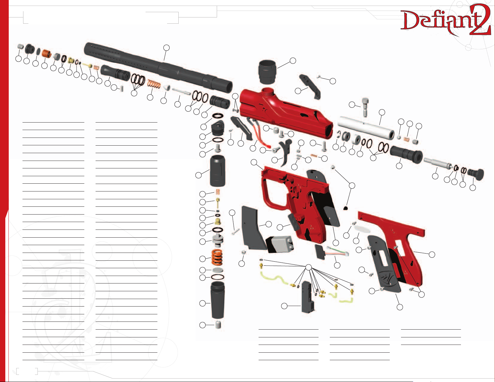
PARTS CHECKLIST
1. LPR Adjustment Screw
2. LPR Front End Cap
3. LPR Spring Washer
4. LPR Spring
5. LPR Piston
6. LPR Piston O-Rings (011)
7. LPR Brass Nut (2 per marker)
8. LPR Brass Nut O-ring (010)
9. Regulator Seat Washer (006)
10. Regulator Pin Valve (2 per marker)
11. Pin Valve Spring (2 per marker)
12. LPR Housing/Base
13. LPR Retaining Screw
14. LPR Housing O-rings (015)
15. Poppet Spring
16. Poppet Cup Seal
17. Poppet Shaft
18a. FRONT Air Valve O-Rings (112)
18b. REAR Air Valve O-Ring (015)
19. Air Valve
20. ASA Mounting O-ring (113)
21. ASA Receiver
22. ASA Thread Base O-ring (015)
23. ASA Retaining Screw
24. HPR Upper Housing
25. HPR Piston O-ring (113)
26. HPR Piston
27. HPR Spring
28. HPR Spring Washer
29. HPR Lower Housing O-ring (118)
30. HPR Lower Housing
31. HPR Adjustment Screw
32. Eye Cover Retaining Screws
33. Eye Covers
34. Eye Wire Harness
35. Valve Retaining Screw
36. Grip Mounting Screws
37a. LEFT Rubber Grip Panel
37b. RIGHT Rubber Grip Panel
38. Trigger Frame Assembly Screws
39. Bob Long Jewel Sticker
40. Left Side Trigger Frame
41. Upper Board Retaining Screw
42. Lower Board Retaining Screw
43. Frenzy Board
44. Membrane Pad & Ribbon
45. Battery & Solenoid Harness
46. Solenoid
47. Air Barbs & Washers (6 per marker)
48. Trigger Retaining Screw
49. Trigger
50. Return Spring Tension Screw
51. Microswitch Activation Screw
52. Trigger Travel Stop Screw
53. Trigger Return Spring
54. FRONT Frame Mounting Screw
55. REAR Frame Mounting Screw
56. Right Side Trigger Frame
57. Bolt Receiver Retaining E-clip
58. Slotted Bolt Receiver
59. Bolt Receiver Spacer (Delrin)
60. Front Ram Sleeve O-ring (012)
61. Ram Sleeve O-rings (015)
62. Encapsulated Ram Sleeve
Designed by Robert Rivera - 305.819.1009
123
57 58 59 60
62
63
67
66
65
64
61
456789101112
15 16 17
18a 18b 19
20
21
22
13
14
23
11
10
46
8
9
7
25
26
27
28
38
39
36
38
36
29
30
31
24
33
32
34
42
54
50
51
32
53
40
36
37b
45
55
72
33
74
69
71
75
68
70
73
35
48
56
44
41
43
38
37a
47
49
52
63. Ram/Hammer
64. Rear Ram O-ring (011)
65. Ram Bumper (006-teflon)
66. Ram Cap O-Rings (011)
67. Ram Sleeve Cap
68. Bolt Pin Tension Set Screw
69. Bolt Pin Tension Spring
70. Bolt Pin Retaining Bearing
71. Delrin Bolt
72. Bolt Pin
73. Feedneck
74. Transfer Hole Screw & Washer
75. 12” Assassin Barrel
To order parts for your DEFIANT 2, please call (925) 625-7929. Please have part numbers ready.
Defiant 2 Manual ƒ 5/31/05 5:47 PM Page 27
Table of contents


