Bob Long Technologies Alias Intimidator User manual

2005
Operator’s Manual
Photography & Design by Robert Rivera - 305.819.1009
A-Bomb Dark
Ripper 2 Ripper 2.5

Congratulations on your purchase of the Intimidator Paintball Marker.
The Intimidator represents the latest in Paintball Marker technology
at a very affordable price. Before operating your Intimidator,please
read the entire manual thoroughly.
WARNING!
This Paintball Marker is not a toy. Misuse or mishandling can result in serious injury
or death. Every person within range of a loaded Paintball Marker must wear eye protection
specifically designed for Paintball. Recommended at least 18 years of age to purchase,
14 years old to use with adult supervision or 10 years old to use on Paintball fields
meeting ASTM standards F1777-97. Be sure to read the entire instruction manual
before operating your Intimidator.
SAFETY!
Please follow all local, state, and federal laws concerning the operation and use of Paintball
Markers. By purchasing this Paintball Marker “YOU” assume all liability.B.L.A.S.T.
assumes no liability for injury or death due to misuse or mishandling of this Marker.
CAUTION!
Never point a Paintball Marker at anyone not wearing Paintball-Approved goggles.
Even at the lowest possible operating velocity, a Paintball will cause serious injury
should it hit someone in the eye area.
Never under any circumstances look down the barrel of your Marker. Even if
wearing Paintball approved goggles, you should Never look down the barrel.
Before performing any maintenance on the Marker, ensure air source is
disconnected and Marker has been degassed. Always ensure Marker is OFF
whenever Marker is not operational.
Always insert barrel plug in barrel when Marker is not operational. Remove barrel
plug only in designated operational areas.
Only play at commercial playing fields that have a chronograph, referees, and clearly
marked safe areas. Chronograph your Marker before each game to ensure Marker is
operating at a safe velocity. Safe velocity is considered to be 280 feet per second (fps).
B
B
o
o
b
b
L
L
o
o
n
n
g
g
i
i
n
n
t
t
i
i
m
m
i
i
d
d
a
a
t
t
o
o
r
r
B
B
o
o
b
b
L
L
o
o
n
n
g
g
i
i
n
n
t
t
i
i
m
m
i
i
d
d
a
a
t
t
o
o
r
r
2005
Table of Contents
Section Page
Safety . . . . . . . . . . . . . . . . . . . . . . . . . . . . . . . . . . . . . . . . . . . . . . . . . . . . .2
Warranty . . . . . . . . . . . . . . . . . . . . . . . . . . . . . . . . . . . . . . . . . . . . . . . . . . .3
History (theory of operation). . . . . . . . . . . . . . . . . . . . . . . . . . . . . . . . . . .3
General Description . . . . . . . . . . . . . . . . . . . . . . . . . . . . . . . . . . . . . . . . . . .3
Introduction . . . . . . . . . . . . . . . . . . . . . . . . . . . . . . . . . . . . . . . . . . . . . . . .4
Ammunition Aspects . . . . . . . . . . . . . . . . . . . . . . . . . . . . . . . . . . . . . . . . . .5
Hopper . . . . . . . . . . . . . . . . . . . . . . . . . . . . . . . . . . . . . . . . . . . . . . . . . .5
Paint . . . . . . . . . . . . . . . . . . . . . . . . . . . . . . . . . . . . . . . . . . . . . . . . . . .5
Operation . . . . . . . . . . . . . . . . . . . . . . . . . . . . . . . . . . . . . . . . . . . . . . . . . . .6
Gas Configurations . . . . . . . . . . . . . . . . . . . . . . . . . . . . . . . . . . . . . . . . .6
Electronics . . . . . . . . . . . . . . . . . . . . . . . . . . . . . . . . . . . . . . . . . . . . . . . . .7
Battery Information . . . . . . . . . . . . . . . . . . . . . . . . . . . . . . . . . . . . . . . . .7
Anti Chop Eyes . . . . . . . . . . . . . . . . . . . . . . . . . . . . . . . . . . . . . . . . . . . .7
Board Operation . . . . . . . . . . . . . . . . . . . . . . . . . . . . . . . . . . . . . . . . . . . . .8
Powering Up . . . . . . . . . . . . . . . . . . . . . . . . . . . . . . . . . . . . . . . . . . . . . .8
LCD Screen . . . . . . . . . . . . . . . . . . . . . . . . . . . . . . . . . . . . . . . . . . . . . . .8
Modes of Operation . . . . . . . . . . . . . . . . . . . . . . . . . . . . . . . . . . . . . . . . .8
Mode Selection . . . . . . . . . . . . . . . . . . . . . . . . . . . . . . . . . . . . . . . . . . . . .9
Competition Lock . . . . . . . . . . . . . . . . . . . . . . . . . . . . . . . . . . . . . . . . . .10
Assembly & Disassemly . . . . . . . . . . . . . . . . . . . . . . . . . . . . . . . . . . . . . .11
Trigger Disassembly . . . . . . . . . . . . . . . . . . . . . . . . . . . . . . . . . . . . . . . .11
Regulator Disassembly . . . . . . . . . . . . . . . . . . . . . . . . . . . . . . . . . . . . . .13
Body Disassembly . . . . . . . . . . . . . . . . . . . . . . . . . . . . . . . . . . . . . . . . . .15
Assembly Tips . . . . . . . . . . . . . . . . . . . . . . . . . . . . . . . . . . . . . . . . . . . . .17
General Maintenance . . . . . . . . . . . . . . . . . . . . . . . . . . . . . . . . . . . . . . . .18
Consumables . . . . . . . . . . . . . . . . . . . . . . . . . . . . . . . . . . . . . . . . . . . . .18
Troubleshooting . . . . . . . . . . . . . . . . . . . . . . . . . . . . . . . . . . . . . . . . . . . .19
Technical Specifications . . . . . . . . . . . . . . . . . . . . . . . . . . . . . . . . . . . . . .21
O-ring Specifications/Identification . . . . . . . . . . . . . . . . . . . . . . . . . . . .21
Screw Specifications/Identification . . . . . . . . . . . . . . . . . . . . . . . . . . . .23
Complete Parts List . . . . . . . . . . . . . . . . . . . . . . . . . . . . . . . . . . . . . . . . .25
21

B
B
o
o
b
b
L
L
o
o
n
n
g
g
i
i
n
n
t
t
i
i
m
m
i
i
d
d
a
a
t
t
o
o
r
r
B
B
o
o
b
b
L
L
o
o
n
n
g
g
i
i
n
n
t
t
i
i
m
m
i
i
d
d
a
a
t
t
o
o
r
r
2005
WARNING!
Always ensure Marker is not shooting at a dangerous velocity. Ensure all participants
are wearing the proper Paintball safety equipment. You will be held liable if someone
is hurt by a Paintball fired from your Marker regardless of fault.
WARRANTY
B.L.A.S.T. warrantees the Intimidator against damages in Manufacturing Defects only.
Electrical components are warranted for a period of 90 days. Solenoids are not warranted.
When utilizing after market Drop-Forwards ensure attachment bolts DO NOT protrude
into internal grip assembly. When utilizing aftermarket grips ensure attachment bolts
DO NOT protrude into internal grip assembly. Failure to do so may damage the internals
and will result in void of warranty. Use of Teflon tape will void warranty. Aftermarket
anodizing will result in void of warranty.
For questions concerning your Intimidator manual please call (925) 625-7929.
OPERATION
The Intimidator Marker is a solenoid controlled open-bolt design. The bolt is locked
onto a dual pressurized machined slider that is controlled by the solenoid (An electronic
4-way valve control). The back of the chamber is pressurized to move the bolt forward,
and the front is pressurized to move the bolt backward. This allows for very low cycling
pressure, as well as much less cocking recoil.
GENERAL DESCRIPTION
The Intimidator is a low pressure operating, open bolt, electronic Marker, featuring
microchip managed solenoid control, anti-chop eyes (ACE), dedicated low and high
pressure regulators attached to a sculptured regulator mounting block, and unique
patented pending modular ram sleeve.
The field strippable pull pin bolt is connected to a dual pressurized sliding ram. This ram
is held within the modular sleeve located in the lower tube of the body. The low pressure
regulator supplies air through the regulator mounting block to the front barb of the
solenoid. Upon activation, the solenoid redirects alternating pressure through the rear
barbs, from the chamber in front of the ram to the back chamber behind the ram. The
forward shifting ram will then strike the poppet, opening the main valve which releases
high pressure regulated air up through the transfer port and into the upper tube of the
body. The pull pin connected bolt pushes the paintball into the breech while simultaneously
redirecting the charge of air to propel the projectile (paintball)to its target.
Introduction
The Intimidator is controlled via the MEMBRANE PAD located on the rear of the Trigger
Frame. All of the functions of the Intimidator can be easily accessed and changed through
the Membrane Pad.
GETTING STARTED
To power up your Intimidator, Press the ON/OFF button. To turn off your Intimidator,
press and hold ON/OFF button for approximately 1 second and release. Buttons 1 and
2 allow the user to scroll, select, adjust, and save settings through the menus as well as
timer activation, stop and reset. Pressing and holding buttons 1 and 2 simultaneously
will open Menu Mode. Once in the Menu Mode, button 1 controls scrolling as well as
the adjustments made to settings while button 2 controls selection and saving of menu
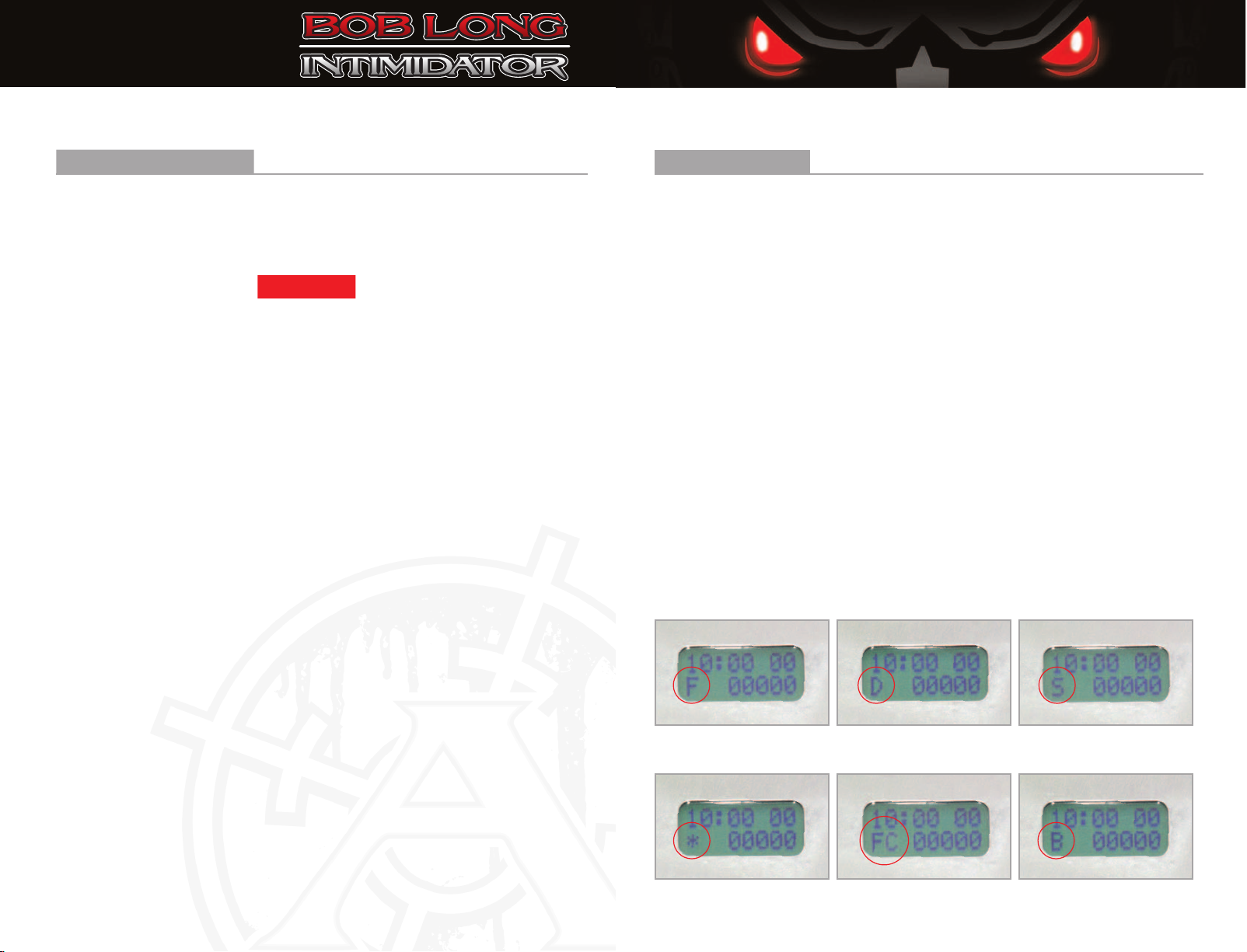
settings. Every Intimidator is equipped with an LCD screen, located on the side grip
panel (left of the membrane pad)which allows the user to verify menu settings along
with voltage, timer, shot counter, eye status, tournament lock, and others, depending
on the software version installed on the circuit board. A detailed description of each
function can be found in the Board Operation section.
NOTE: The Frenzy Board IS NOT Programmable via the trigger.
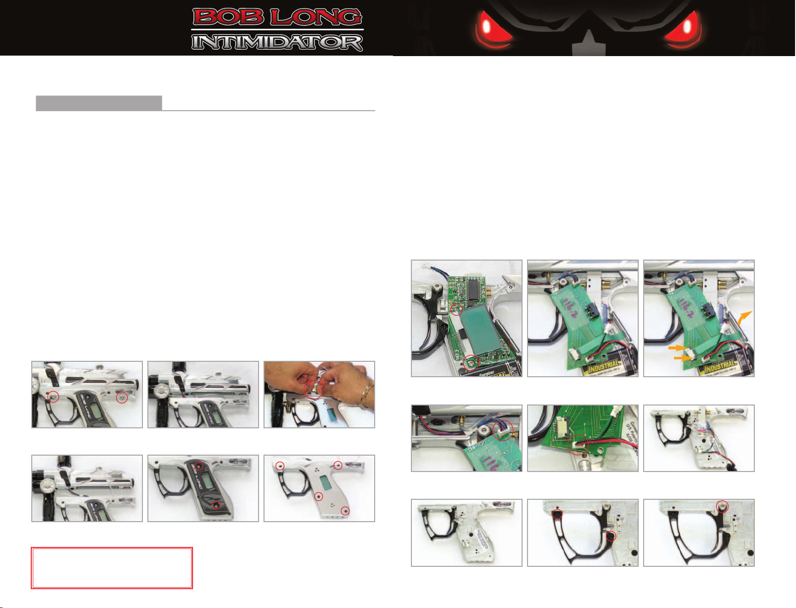
TRIGGER ADJUSTMENT
The trigger is fully adjustable using the three screws within the trigger. The upper
screw controls the return spring tension, the center screw adjusts micro-switch activation
point and the lower screw adjusts the trigger stop point.
BARREL
The Intimidator comes standard with a one piece, .689 Bore, 12-inch Assassin barrel.
Barrel threads for the Intimidator are Auto-cocker type.
SPECIFICATIONS
Model . . . . . . . . . . . . . . . . . . . . . . . . . . . . . . . . . . . . . . . . . . . .Alias Intimidator
Caliber . . . . . . . . . . . . . . . . . . . . . . . . . . . . . . . . . . . . . . . . . . . . . . . . . . . . . . . 68
Action . . . . . . . . . . . . . . . . . . . . . . . . . . . . . . . . . . . . . . . . . . .Electro-Pneumatic
Air Source . . . . . . . . . . . . . . . . . . . . . . . . . . . . . . . . . . .Compressed Air/Nitrogen
Battery Type . . . . . . . . . . . . . . . . . . . . . . . . . . . . . . . . . . . . . . . . . .9-Volt Battery
Cycle Rate . . . . . . . . . . . . . . . . . . . . . . . . . . . . . . . . . . . . .Unlimited Semi Mode
Effective Range . . . . . . . . . . . . . . . . . . . . . . . . . . . . . . . . . . . . . . . . . . .150+ feet
Weight . . . . . . . . . . . . . . . . . . . . . . . . . . . . . . . . . . . . . . . . . .2 pounds, 5 ounces
Length . . . . . . . . . . . . . . . . . . . . . . . . . . . . . . . . . . . . . .(12” barrel)19.25 inches
Height . . . . . . . . . . . . . . . . . . . . . . . . . . . . . . . . . . . . . . . . . . . . . . . . . . .8 inches
*
Weight of Marker without 12” Assassin Barrel is 1lbs., 13oz.
*
43

B
B
o
o
b
b
L
L
o
o
n
n
g
g
i
i
n
n
t
t
i
i
m
m
i
i
d
d
a
a
t
t
o
o
r
r
B
B
o
o
b
b
L
L
o
o
n
n
g
g
i
i
n
n
t
t
i
i
m
m
i
i
d
d
a
a
t
t
o
o
r
r
Introduction
(continued)
REGULATORS
Included with the Intimidator are 2 High-Flow Regulators. Both regulators use
a standard 3/16 inch hex key for adjustment. Turn the adjustment screw
clockwise to increase pressure and counter-clockwise to decrease pressure.
Low Pressure Regulator
The low pressure regulator is mounted towards the front of the Marker under the barrel.
It controls the cycling pressure of the Marker which is read with the 0-300 PSI Ashcroft gauge
located on the left side of the block. The pressure should be set between 70 – 80 PSI.
NEVER EXCEED 100 PSI AS OVER-PRESSURIZING CAN DAMAGE SOLENOID. The low
pressure regulator is not used for velocity adjustments but for cycling pressures only.
High Pressure Regulator
The high pressure regulator (also called the Torpedo or inline regulator) is the vertical regulator
that screws into the bottom of the ASA block. All velocity adjustments are done with the Torpedo
regulator. Typically, pressures vary from 200 PSI to 280 PSI depending on chronograph speed.
If an aftermarket volumizer is used, the pressure may be lowered accordingly. Please note: The
Torpedo high pressure regulator comes with 2 connection ports, 1 dedicated for the air input
and the other dedicated for a gauge to monitor pressure levels. To verify that you are connecting
an air fitting to the appropriate input port of your Torpedo regulator, the pin valve assembly
will be visible within that port prior to installation. The gauge port comes with a plug screw
pre-installed from the factory.
Ammunition Aspects
Hopper
The Intimidator requires a high feed rate of paintballs to make full use of its features.
To satisfy this need, the use of a motorized loader is recommended.
Paint
Using top grade paint ensures the utmost in performance and accuracy.
Operatio
n
Gas Configurations
PRESET AND ADJUSTABLE TANKS
A Compressed Air System also known as a Nitrogen Air System is the recommended propellant air
source for operating the Intimidator. If you are using an Adjustable Tank the output should be set
between 400 & 500 PSI, and Preset Tanks should be low pressure or 400 PSI output, but a high
pressure system is acceptable.
Co2
Co2 IS NOT the recommended propellant for the Intimidator. You should only use a Compressed
Air System to operate your Intimidator. When attaching air system hose fittings to your Marker,
DO NOT USE TEFLON TAPE. Use a thread sealant such as Loctite 545 instead.
GETTING STARTED
Maintenance for the Intimidator is very simple.
The Bolt should be lubricated sparingly with TRI-FLOW. Lubricating once a day or when dirty
will increase the life of the Ball Detents and also eliminate bolt drag.
The Ram or “Hammer” should be greased every 5000 shots with DOW 55. First degas your
Marker. Next, remove Bolt and Ram Sleeve End Cap and Ram will slide out of the back. Clean inside
of Ram Sleeve with a Q-tip, grease O-rings with DOW 55 and reassemble.
The Low Pressure Regulator Piston and the High-Pressure Regulator Piston O-rings should be
greased every 10,000 shots. The final o-ring to lubricate is the Poppet O-ring, located in front
of the Ram Sleeve. It is accessed by removing the front Regulator/ASA Block. This should be
done every 20,000 shots. Performing this simple maintenance will increase the life of the O-rings
and keep the Marker performing at the highest level possible.
NOTE: Always ensure Air Source is disconnected and Marker is fully degassed
BEFORE performing any/all maintenance, or when Marker is not operational.
2005
65

B
B
o
o
b
b
L
L
o
o
n
n
g
g
i
i
n
n
t
t
i
i
m
m
i
i
d
d
a
a
t
t
o
o
r
r
B
B
o
o
b
b
L
L
o
o
n
n
g
g
i
i
n
n
t
t
i
i
m
m
i
i
d
d
a
a
t
t
o
o
r
r
Electronics
Battery Information
The Intimidator uses a standard 9v battery. To change the battery, remove the Left Rubber
Grip Panel, then remove the 4 allen screws securing the two Trigger Frame halves. You’ll
notice the battery fits into the bottom of the Trigger Frame. Disconnect the old battery and
re-connect the new.
WARNING!
At this time it is good to verify screws are not protruding through the bottom of the grip
and into the interior components. Failure to do so may result in damage to the battery
and/or Circuit Board.
ANTI-CHOP EYES (ACE)
The Intimidator is the first Production Marker to incorporate a break beam Anti-Chop Eye
system in a Production Marker, commonly referred to as the ACE system. The ACE system
consists of a set of sensors mounted near the bottom of the breech to restrict firing until a
ball is completely loaded into the breech. Always operate the Intimidator with the eyes ON.
Failure to do so will more than likely result in broken paint in the breech. The transmitter eye
can be identified by the red and black wires, metal casing and male connector. The receiver
eye can be identified by it’s blue and black wires, black plastic casing and female connector.
Factory Settings
Standard factory FRENZY Board settings are as follows:
DWELL . . . . . . . . . . . . . . . . . . . . . . . . . . 8 ms
EYE . . . . . . . . . . . . . . . . . . . . . . . . . . . Delay
BIP . . . . . . . . . . . . . . . . . . . . . . . . . . . 0.5 ms
BOLT DELAY . . . . . . . . . . . . . . . . . . . . . 15ms
TIMER . . . . . . . . . . . . . . . . . . . . . . . . . 10.00
DEBOUNCE . . . . . . . . . . . . . . . . . . . . . 12 ms
MBOUNCE . . . . . . . . . . . . . . . . . . . . . . . . . . 2
DELAY . . . . . . . . . . . . . . . . . . . . . . . . . . . . 10
A detailed description of each function is in the board operation section.
Board Operatio
n
Getting Started
POWERING UP
1. To power up your Intimidator, press the ON/OFF button.
2. To turn off your Intimidator, press and hold the ON/OFF button for approximately 1 second.
The LCD will display [TURNING OFF] and go blank. Release the ON/OFF Button.
Your Intimidator is now OFF.
LIQUID CRYSTAL DISPLAY (LCD)
Once the Marker is powered up, the LCD will display characters representing the status of the Marker.
The characters are located on the 2nd line of the LCD and are as follows:
Standard Operation Modes
1. [ F ]- Indicates FORCED Mode
2. [ D]- Indicates DELAY Mode
3. [ S ]- Indicates DRY FIRE Mode
(Formerly known as SIMULATION Mode. Demonstrates how the Marker should
operate with an appropriate supply of paintballs and fully charged air system.)
Non-Standard Operation Modes/Warnings
4. [*]- Indicates EYE SENSOR MALFUNCTION (Marker will be limited to 12bps)
5. [C]- Indicates COMPETITION Mode is ON
6. [B]- Indicates BATTERY IS LOW
Views of each mode selection on the Circuit Board can be seen below.
FORCED Mode DELAY Mode DRY FIRE Mode
EYE SENSOR MALFUNCTION COMPETITION Mode ON BATTERYIS LOW
2005
87
123
456

B
B
o
o
b
b
L
L
o
o
n
n
g
g
i
i
n
n
t
t
i
i
m
m
i
i
d
d
a
a
t
t
o
o
r
r
B
B
o
o
b
b
L
L
o
o
n
n
g
g
i
i
n
n
t
t
i
i
m
m
i
i
d
d
a
a
t
t
o
o
r
r
Board Operatio
n
Getting Started
MODE SELECTION (Version 116.2 FRENZY only)
The LCD is a Two-Button Membrane and Menu driven system. To bring up menu options for the
Marker, press and hold down Buttons 1 and 2 for approximately 1 second. Upon release you will
be taken to the first menu. Button 1 scrolls through the available menus. Button 2 is for entering
a selected menu. Once inside of a given menu, pressing Button 1 will change the current setting
within that menu incrementally. Pressing Button 2 will save the current setting and instantly exit
the Menu Mode. The Marker will now fire using the latest selected modes. Below are descriptions
of the different modes and how they affect the Marker’s performance.
DWELL - Determines how long the bolt remains in the forward position before repeating cycle.
EYE - Activates or Deactivates the ACE System with the following options:
FORCE - Marker fires only when ball is present at time of trigger pull.
DELAY- Marker fires when ball is present at time of trigger pull. However, if a ball IS NOT
present or detected, the Marker will wait 1 second before firing.
DRY FIRE - ACE System is Bypassed (OFF)and Marker fires at time of trigger pull.
NOTE: Eye setting can be changed to dry fire mode without entering the menu. With
the Marker OFF, hold trigger in and turn Marker ON until the LCD goes to its normal
screen and S is on the bottom left of the screen, now release trigger. This will set the
Marker to Dry Fire Mode with the eye sensor off. This function is disabled with
Competition Lock.
BIP (Ball in Place)- Determines how long after a Trigger Pull and Ball Detection, the Marker
will fire. Caution: Setting too low may induce ball breakage.
BOLTDELAY- Time eye sensor is ignored. This time allows Bolt to move forward.
Caution: Setting too low may cause Marker to dry fire.
TIMER - Determines game timer setting.
DEBOUNCE - Determines (in milli seconds) how long after each trigger pull, the board will
ignore further trigger activity.
M-BOUNCE - Mechanical Bounce setting is used to stop Marker’s recoil from causing an added
shot. 0 deactivates, while higher numbers decrease sensitivity of mechanical bounces occurring.
DELAY - Delay is used to slow down the Marker’s cycling speed. The higher the number, the
slower the Marker will cycle.
COMPETITION LOCK - With Competition Lock ON, Dwell, Delay, Debounce, and M-Bounce Menus
are not accessible. All other Menus are accessable as usual, however, the trigger activated Dry Fire
Mode is disabled. When Competition Lock is active, the display window of the LCD will show [C]as
the second character on the 2nd line. (Marker is not BPS capped while using Competition Lock)
2005
Board Operatio
n
TO ACTIVATE COMPETITION LOCK:
1. Turn Marker OFF.
2. Open up Trigger Frame to gain access to the Circuit Board.
3. Short out Cand DTerminals (holes)of the top of the board.
Paper clips work well for this. Bend the clip so that one
end is touching the Dand the other end is touching C.
4a. Turn Marker ON.
4b. The display window will show “Comp On” then in the
normal window the display will show [C].(see figure 8)
5. Turn Marker OFF.
6. Disconnect the Dand Cshort and leave off
for at least 30 seconds.
7. Reassemble Trigger Frame.
8. Ready to use with COMPETITION LOCK.
To turn OFF Competition Lock follow the same procedure.
When not activated the display will not show [C]on the LCD.
For information and instructions regarding previous and/or
future versions of the FRENZY Board (Other than version 116.2),
please refer to separate instructions sheet included in box.
109
Turn Marker OFF
1
Open Trigger Frame
2
Disconnect Short, Leave OFF Reassemble Trigger Frame COMPETITION LOCK
678
Short out C and D Terminals Turn ON Comp Lock ON Turn OFF
34b 54a
Terminals
C D

B
B
o
o
b
b
L
L
o
o
n
n
g
g
i
i
n
n
t
t
i
i
m
m
i
i
d
d
a
a
t
t
o
o
r
r
B
B
o
o
b
b
L
L
o
o
n
n
g
g
i
i
n
n
t
t
i
i
m
m
i
i
d
d
a
a
t
t
o
o
r
r
Assembly and Disassembly
Getting Started
WHEN DISASSEMBLING THE INTIMIDATOR ALWAYS ENSURE THE MARKER IS DEGASSED.
The DISASSEMBLY portion of this manual will be divided into three sections.
I. Trigger Disassembly
II. Regulator Disassembly
III. Body Disassembly
NOTE: When ASSEMBLING the Intimidator, perform the entire disassembly
process in reverse order.
I. TRIGGER DISASSEMBLY
1. Remove 2 Trigger Assembly retaining screws. Ensure both washers are installed during assembly.
2. Separate Trigger Assembly from Main Body to expose airlines.
3. Disconnect both Eye Sensor Harnesses.
4. Disconnect all 3 Airlines (Hoses) from body.
NOTE: Use care when removing airlines.
Always inspect hoses after removal to ensure no tears or damage occurred during removal.
5. Remove left side LCD Grip.
6. Remove 4 allens to separate Trigger Frame Halves.
11
Assembly and Disassembly
TRIGGER DISASSEMBLY (continued)
7. Remove 2 Board retaining screws. (1 1/16 Allen Head screw and 1 Phillips Head screw)
8. Flip Board over towards left side.
9. Lift up on black LCD ribbon locks located on each side of membrane ribbon harness and
remove complete membrane assembly from trigger frame.
10. Remove Eye Sensor Wire Harness.
11. Remove Battery and Solenoid Harness.
12. Remove Circuit Board.
13. Remove Solenoid.
14. Remove 2 Trigger Guard Screws to remove Guard.
15. Remove Shouldered Trigger Retaining Screw and lift out Trigger and Trigger Return Spring.
2005
12
Disconnect Hoses Grip Removal Separate Trigger Halves
Trigger Assembly Screws Separate Frame From Body Disconnect Eye Harnesses
WARNING!
Ensure Air Source is disconnected and Marker
is discharged before making any mechanical
adjustments to Marker internals or electronics. Remove Solenoid Trigger Guard Removal Remove Trigger Screw
Remove Eye Wire Harness Remove Noid & Batt. Harness Remove Circuit Board
Lift up LCD Ribbon LocksFlip Board to Expose Wiring
Remove Board Retaining Screws
123
6
45
789
10 11 12
13 14 15

B
B
o
o
b
b
L
L
o
o
n
n
g
g
i
i
n
n
t
t
i
i
m
m
i
i
d
d
a
a
t
t
o
o
r
r
B
B
o
o
b
b
L
L
o
o
n
n
g
g
i
i
n
n
t
t
i
i
m
m
i
i
d
d
a
a
t
t
o
o
r
r
Assembly and Disassembly
REGULATOR DISASSEMBLY (continued)
TORPEDO/HIGH-PRESSURE REGULATOR (HPR)
1. Unscrew Allen Adjuster.
2. Unscrew Lower End of (HPR)
High-Pressure Regulator Housing.
3. Remove Regulator Spring Washer.
4. Remove Regulator Spring.
5. Remove Piston.
NOTE: At this time the Regulators are disassembled. Listed below are key elements to
remember during assembly.
1. Piston: Ensure cupped end of Piston is facing towards Pin Valve.
2. Pin Valve: Ensure Pin Valve is not bent and seats in cupped end of Piston.
Failure to do so will cause Regulators to function improperly.
3. Air Barb: Ensure fiber washer is on Air Barb base when installing.
This will ensure Air Barb does not leak.
4. Poppet Spring Attachment: Ensure small end of Spring sits firmly on Poppet.
5. ASA Block: Place small portion of Loctite on Retaining Allen when installing.
This will ensure ASA (regulator) Base does not work itself loose during operation.
6. Remove Pin Valve Retainer.
7. Remove Teflon Washer.
8. Remove Pin Valve.
9. Remove Spring from Upper Reg. Housing.
10. Upper End of (HPR)High-Pressure
Regulator Housing.
6. Remove Pin Valve Retainer.
7. Remove Teflon Washer.
8. Remove Pin Valve.
9. Remove Spring from Upper Reg. Housing.
10. ASA End of (LPR) Low-Pressure
Regulator Housing.
2005
Torpedo/High-Pressure Regulator
35 48 67910 12
LOW PRESSURE REGULATOR (LPR)
1. Unscrew Allen Adjuster.
2. Unscrew Adjustment End (Part 2)from ASA
End (Part 10)of Low-Pressure Regulator.
3. Remove Regulator Spring Washer.
4. Remove Regulator Spring.
5. Remove Piston.
Low-Pressure Regulator
3 54 86 7 9 101 2
Assembly and Disassembly
II. REGULATOR DISASSEMBLY
ASA BLOCK/HOUSING
First: Remove Both Regulators.
1. Remove Air Barb from ASA Block.*
2. Remove Regulator Base Retaining
Screw from Body.
3. Slide Regulator Base from Body.
4. Remove Spring and Poppet.
*Use great caution when Removing or Reinstalling Air Barbs as they are somewhat delicate. Air Barb on front Block must be
removed in order to gain proper acces to Regulator Base Retaining Screw. Failure to do so may result in damage to the Air Barb.
Remove ASA Retaining Allen Slide Regulator Base from Body Remove Spring and Poppet
234
Remove Air Barb from ASA Block
1
13 14

2005
B
B
o
o
b
b
L
L
o
o
n
n
g
g
i
i
n
n
t
t
i
i
m
m
i
i
d
d
a
a
t
t
o
o
r
r
B
B
o
o
b
b
L
L
o
o
n
n
g
g
i
i
n
n
t
t
i
i
m
m
i
i
d
d
a
a
t
t
o
o
r
r
Assembly and Disassembly
BODY DISASSEMBLY (continued)
8. Remove Air Barb from Back of Ram Sleeve. Do not lose fiber washer at base of Air Barb.
9. Remove Ram Sleeve retaining allen.
10. At this time you are ready to remove the Ram Sleeve from the body. When removing,
. rotate the Ram Sleeve right and left pulling towards the rear of the Marker. Use caution
. to avoid cutting the O-rings, as there are sharp edges the O-rings must pass through.
. NOTE: When reinstalling Ram Sleeve, it must be inserted through the front end
. of the Lower Tube of the Marker Body in order to ensure a proper seal.
11a. Remove Feedneck by first removing Feedneck Collar, then removing Feedneck Base.
11b. Remove Feedneck Base from Body.
NOTE: At this time the Body is disassembled.
Listed on the following page are key points
to remember during assembly.
Assembly and Disassembly
III. BODY DISASSEMBLY
First: Ensure Barrel of Marker is removed.
1. Remove both Eye Sensor Covers (one on each side)by removing Retaining Screw.
2. Remove both Eye Sensors (one on each side)by carefully pulling sensor heads from
mounting holes. Be careful not to lose small o-ring on each head.
3. Lift up on Bolt Retaining Pin and slide Bolt out of rear of Marker.
4. Remove Ram Sleeve Cap located at the rear of Marker. (turn counter-clockwise)
5. Turn Marker up and allow ram to slide out of Marker rear. Place hand underneath
to catch ram. Do not allow ram to fall freely onto ground or any other hard surface.
6. Turn Body over to gain access to the bottom of the Marker.
7. Remove Air Barb from Center of Ram Sleeve. Do not lose fiber washer at base of Air Barb.
Remove Eye Sensor Covers
1
Remove Eye Sensors
2
Turn Body over Exposing Bottom of Marker
6
Remove Center Barb
7
Remove Ram Sleeve Retaining Allen
9
Remove Ram Sleeve from Rear
10
Remove Feedneck Base
Remove Feedneck Collar
11 a
1
1b
Lift Bolt Pin and Remove Bolt Remove Ram Sleeve Cap Remove Ram
345
Remove Rear Barb
8
15 16

2005
B
B
o
o
b
b
L
L
o
o
n
n
g
g
i
i
n
n
t
t
i
i
m
m
i
i
d
d
a
a
t
t
o
o
r
r
B
B
o
o
b
b
L
L
o
o
n
n
g
g
i
i
n
n
t
t
i
i
m
m
i
i
d
d
a
a
t
t
o
o
r
r
Assembly and Disassembly
ASSEMBLY TIPS
KEY ELEMENTS TO REMEMBER DURING ASSEMBLY.
O-Rings: LUBRICATE ALL O-RINGS UPON INSTALLATION.
Ram Sleeve O-rings: Always ensure all O-Rings are in good condition upon installation.
Ram Sleeve Installation: The Ram Sleeve should be reinserted through the front end of the
marker body to ensure the U-Cup O-ring maintains a proper seal. Use caution when installing
the Ram Sleeve and take extra care not to cut/damage the O-Rings on the sharp edges of the body.
Air Barb: Ensure fiber washer is on Air Barb base prior to installation. This will ensure a proper seal.
ASA Block Set Screw: Use small amount of Loctite on ASA Housing Retaining Allen when
installing. Failure to do so may result in ASA Block sliding off the Marker Body, causing
extreme damage to the Marker and/or possibly injuring the operator and others. A firm snug is
all that is required to maintain a secure fit.
Poppet installation: Before installation, inspect Poppet thoroughly. If Poppet shows signs of
excessive wear, it must be replaced in order to ensure a proper seal. Ensure Poppet O-Ring is
well lubed when installing. Allow Poppet to slide into Ram Sleeve. Once seated tap on Poppet
end to mate Poppet with Ram Sleeve. Ensure small end of spring seats firmly on Poppet.
Ram Sleeve Retaining Allen: Use small amount of Loctite on Retaining Allen when installing.
Failure to do so may result in Ram Sleeve sliding back, causing extreme damage to the Marker
and/or possibly injuring the operator.
Eye Sensor Harness: Ensure Harness is seated in grove provided before attaching Eye Covers.
Failure to do so may result in pinched wires and render the eyes inoperable.
Eye Covers: Ensure Ball Detents remain aligned and in Covers upon install. Do not over tighten
the cover screws. A firm snugg is all that is required to maintain a secure fit.
Feedneck: Removal of the Feedneck Base may require the use of a Strap Wrench since it is
firmly secured during initial assembly. Simply wrap the Strap around the Feedneck and turn
counter-clockwise. To Reinstall, simply screw the Feedneck back onto the body and secure
firmly using a Strap Wrench.
NOTE: Once Marker is completely disassembled, carefully inspect all Screws, O-Rings, Ball Detents,
Air Barbs, Hoses, Eye Sensors, Wiring, Electronics, Battery, ASA Block, Regulator, and Feedneck
Threads, etc., for signs of premature or excessive wear, stripping and/or damage.
If ANY parts show signs of premature or excessive wear, stripping and/or damage, and you need to
order them, please refer the the chart on the facing page for reference. A more detailed discription
of parts and/or the corresponding PART NUMBER(S)can be found in the COMPLETE PARTS
CHECKLIST located on the inside back cover of the manual. Simply call B.L.A.S.T
. at the number
provided and a Customer Service Representative will assist you.
PLEASE HAVE PART NUMBER(S)READY WHEN CALLING.
Maintenance
GENERAL MAINTENANCE
WARNING: NEVER use lightweight gun oil on Marker. Oil will destroy internals
of Air Valve and O-rings.
Keep foreign obstructions out of Marker internals and Lubricate all O-rings within the Marker a
generous coat of Dow 55 Lubricant. The Ram requires Lubing every 5,000 rds. fired. Regulator
O-rings should be Lubed every 10,000 rds. fired. Failure to do so will reduce recovery time of
Regulators. Additionally, the Piston will wear a groove in the Regulator housing. Ensure the Pin
Valve lines up with the Cupped End on the Piston during reassembly. This will eliminate the
inadvertent bending of the pin. The Poppet O-rings require Lubing every 20,000 rds. fired.
Below is a list of the most common Consumable Components of the Intimidator.
COMPONENT QUANTITY SIZE
Body Assembly
Bolt O-ring 4015
Poppet O-ring 1004
Ram Front O-ring 1006
Ram Rear O-ring 1011
Ram Rear Bumper O-ring (Teflon)1011
Pressurized Ram Sleeve O-ring 2(front O-ring is cupped)015
Sleeve End Cap O-ring 2011
Regulator Assembly
HPR Housing O-ring 1016
HPR Piston O-ring 1113
HPR Pin Valve Base Washer 1010
HPR Pin Valve Washer (Teflon)1006
Teflon LPR Housing O-ring 1016
LPR Piston O-ring 1113
LPR Pin Valve Base 1010
LPR Pin Valve Washer (Teflon)1006
Regulator Base 2015
Trigger Assembly
Airline 1 to regulator base 5.0 in.
Airline 1 to middle body 5.0 in.
Airline 1 to rear body 2.5 in.
Circuit Board 1004
17 18

2005
B
B
o
o
b
b
L
L
o
o
n
n
g
g
i
i
n
n
t
t
i
i
m
m
i
i
d
d
a
a
t
t
o
o
r
r
B
B
o
o
b
b
L
L
o
o
n
n
g
g
i
i
n
n
t
t
i
i
m
m
i
i
d
d
a
a
t
t
o
o
r
r
T
T
r
r
o
o
u
u
b
b
l
l
e
e
s
s
h
h
o
o
o
o
t
t
i
i
n
n
g
g
Troubleshooting
NOTE: Refer to Assembly/Disassembly to perform repairs indicated below.
1. Replace Poppet
2. Replace Ram Sleeve O-rings
3. Remove LPR Block and
replace Poppet O-ring
1. Open Trigger Frame
and reconnect Hose
2. Tighten or Replace
Air Barb
1. Check LPR. It should be
between 70-80 PSI.
2. It is not recommended to
disassemble solenoid. Call
B.L.A.S.T. for assistance
1. Check Dwell and Reset
to Factory Settings
2. Check LPR Gauge. Pressure
should be between 70-80 PSI.
3. Open Frame and check hoses
4. Push Reset Button on
Solenoid when Marker is
pressurized. If Marker
does not fire call B.L.A.S.T.
5. If Board is not counting
it is the Micro-Switch
6. Open Trigger Frame and
check Solenoid connection
1. Lube Piston with DOW 55
2. Check Dwell and set to
Factory Settings
3. Replace 011 O-Ring
4. Check pressure and
reset to 70-80 PSI
5. Use appropriate size
paintball.
REPAIR
1. Poppet is not sealing
2. Ram Sleeve O-rings
are damaged
3. Poppet O-ring is damaged
1. Air Hose has become
disconnected
2. Hose Barb has come loose
or is broken
1. Marker is over pressurized
2. Foreign material has
lodged inside Solenoid
1. Dwell is to low
2. LPR too low
3. Pinched Hose
4. Debris in Solenoid
5. Check shot counter
6. If Board is counting, it
is possible the Solenoid
connector is disconnected
or damaged.
1. High Pressure Regulator
Piston is dry
2. Dwell too low
3. Large Ram O-ring (011)
is worn.
4. LPR Pressure too low
5. Paint does not fit Barrel
DIAGNOSIS
Marker leaks down Barrel
Marker leaks from inside
Trigger Frame
Marker leaks from Solenoid
Marker is pressurized and
will not fire
Inconsistent Velocity
PROBLEM REPAIRDIAGNOSISPROBLEM
1. Replace O-ring
2. Replace regulator seat
3. Tighten Brass Nut
4. Replace O-ring
1. Check Dwell and reset
to Factory Settings
2. Check output pressure of
High-Pressure Regulator
1. Check depth of Pin Valve
2. Check LPR pressure
1. Check and make sure Eyes
are ON and/or operational
2. Replace Ball Detents
3. Size paint for Barrel
4. Use winter-fill paint in
winter or heat your paint
1. Check Eye Alignment
2. Clean Eyes
3. Open and inspect Eye Wires
and Eye Harness Wires
4. Replace Bad Eye(s)
1. Call B.L.A.S.T
.
for assistance
1. Large Square Edged 0-ring
on LPR base is bad
2. Regulator Seat is bad
3. Brass Nut isn’t tight enough
4. 010 0-ring on Brass
Nut is worn or damaged
1. Low dwell
2. High-Pressure Regulator
spiking over pressurizing valve
chamber
1. Preset tank pin valve is
depressed too far or not
enough starving Marker of air
2. LPR pressure too low
1. Eyes are turned off
and/or damaged
2. Missing or worn ball detents
3. Paint to large for barrel
4. Using brittle paint in
cold weather
1. Eyes misaligned
2. Dirty Eyes
3. Pinched or cut wires
4. Bad Eye(s)
1. Faulty Micro-Switch
LPR spikes
Marker fires with low
first shot
Marker dies off with
rapid fire
Marker is Breaking paint
Eyes fail when in delay
Marker fires on pull
and release
19 20

B
B
o
o
b
b
L
L
o
o
n
n
g
g
i
i
n
n
t
t
i
i
m
m
i
i
d
d
a
a
t
t
o
o
r
r
B
B
o
o
b
b
L
L
o
o
n
n
g
g
i
i
n
n
t
t
i
i
m
m
i
i
d
d
a
a
t
t
o
o
r
r
T
T
e
e
c
c
h
h
n
n
i
i
c
c
a
a
l
l
S
S
p
p
e
e
c
c
s
s
Technical Specifications
PARTS IDENTIFICATION
O-ring Sizer/Identifier
O-ring & Size Quantity Discription/Breakdown
Note: O-rings are shown in actual size.
Poppet O-ring
Ram FRONT O-ring
Teflon Regulator Seat Washer
1 Per Marker
1 Per Marker
2 Per Marker
004
006
006 (Polyurethane)
Ram Bumper O-ring1 Per Marker
006 (Teflon)
Brass Nut O-ring for
Low-Pressure Regulator &
High-Pressure Regulator (1 each)
2 Per Marker
1 - Ram REAR
2 - Ram Sleeve Cap
2 - LPR Piston
(Low-Pressure Regulator)
5 Per Marker
010
011
REAR Ram Sleeve O-ring1 Per Marker
112
HPR Piston O-ring
(Torpedo)
1 Per Marker
113
O-ring & Size Quantity Discription/Breakdown
LPR Base “Square Cut”
Outer Most O-ring
1 Per Marker
114
4 - Bolt O-rings
2 - Regulator/ASA Block O-rings
1 - Torpedo Upper End O-ring
7 Per Marker
015
FRONT Ram Sleeve O-ring1 Per Marker
015 (U-Cup)
Torpedo Lower End O-ring1 Per Marker
118
LPR Base Inner Most O-ring1 Per Marker
020
21 22
2005
NOTE: The number below each O-ring on the left column indicates the size of the O-ring.
For instance if you need to purchase a Ram Bumper O-ring, you would ask for an O-ring size 006 Teflon.

T
T
e
e
c
c
h
h
n
n
i
i
c
c
a
a
l
l
S
S
p
p
e
e
c
c
s
s
Trigger Mounting Screw
(Secures Trigger to frame)
1 Per Marker
8/32 x 9/16
(Shouldered)
B
B
o
o
b
b
L
L
o
o
n
n
g
g
i
i
n
n
t
t
i
i
m
m
i
i
d
d
a
a
t
t
o
o
r
r
B
B
o
o
b
b
L
L
o
o
n
n
g
g
i
i
n
n
t
t
i
i
m
m
i
i
d
d
a
a
t
t
o
o
r
r
Technical Specifications
PARTS IDENTIFICATION (continued)
Screw Sizer/Identifier
Screw & Size Quantity Discription/Breakdown
NOTE: The number below each Screw on the left column indicates the size of the Screw. For instance if
you need to purchase a LOWER Circuit Board Retaining Screw, you would ask for a 4/40 x 1/4 LOWER
Circuit Board retaining Screw.
Rubber Grip Screws4 Per Marker
6/32 x 3/16
4 - Trigger Frame Screws
2 - Trigger Gaurd Screws
6 Per Marker
4/40 x 1/4
Trigger Frame Mounting Screw Washers2 Per Marker
4/40 x 1/4
Trigger Frame Mounting Screws2 Per Marker
3/32 x 3/4
Upper Circuit Board Retaining Screw1 Per Marker
0/80 x 3/8
Lower Circuit Board Retaining Screw1 Per Marker
4/40 x 1/4
Upper Trigger Adjustment Screw
(Adjusts Return Spring Tension)
1 Per Marker
8/32 x 1/4
Center Trigger Adjustment Screw
(Adjusts Micro-Switch Activation Point)
1 Per Marker
6/32 x 1/2
Lower Trigger Adjustment Screw
(Adjusts Trigger Travel Stop Point)
1 Per Marker
6/32 x 3/16
Retaining Set Screw for Bolt Pull Pin1 Per Marker
10/32 x 1/2
ASA Block Set Screw1 Per Marker
3/8 x 24 x 1/2
HPR Gauge Port PLug1 Per Marker
1/8 x 27
Ram Sleeve Set Screw1 Per Marker
3/8 x 24 x 3/8
LPR Pressure Adjustment Screw1 Per Marker
3/8 x 24 x 3/8
HPR Pressure Adjustment Screw
1 Per Marker
3/8 x 24 x 3/8
Eye Cover Screws2 Per Marker
2/56 x 3/8
23 24
2005
(Stainless Steel)
(Stainless Steel)
(Stainless Steel)
(Stainless Steel)
(Stainless Steel)
(Stainless Steel)
(Stainless Steel)
(Stainless Steel)
(Stainless Steel)
(Stainless Steel)
Note: Screws are shown in actual size.

2005
Parts Checklist
B
B
o
o
b
b
L
L
o
o
n
n
g
g
i
i
n
n
t
t
i
i
m
m
i
i
d
d
a
a
t
t
o
o
r
r
B
B
o
o
b
b
L
L
o
o
n
n
g
g
i
i
n
n
t
t
i
i
m
m
i
i
d
d
a
a
t
t
o
o
r
r
PARTS CHECKLIST
1.
LPR Adjustment Screw
2.
LPR Front End Cap
3.
LPR Spring Washer
4.
LPR Spring
5.
LPR Piston
6.
LPR Piston O-Rings (011)
7.
LPR Brass Nut (2 per marker)
8.
LPR Brass Nut O-ring (010)
9.
Regulator Seat Washer (006)
10.
Regulator Pin Valve (2 per marker)
11.
Pin Valve Spring (2 per marker)
12.
LPR Housing/Base
16.
LPR Inner Base O-ring (020)
14.
LPR Outer Base O-ring (114)
15.
ASA Block/Housing
16.
LPR Pressure Gauge
17.
Air Barbs & Washers (6 per marker)
18.
ASA Block O-rings (015)
19.
HPR Upper Housing
20.
HPR Gauge Port Plug
21.
HPR Piston O-ring (113)
22.
HPR Piston
23.
HPR Spring
24.
HPR Spring Washer
25.
HPR Lower Housing
26.
HPR Adjustment Screw
27a.
Feedneck Collar
27b.
Feedneck Base
28.
Marker Body
29.
Ball Detent (2per marker)
30.
Eye Sensors (2 per marker)
31.
Eye Covers (2 per marker)
32.
Eye Cover Retaining Screws
33.
ASA Housing Retaining Screw
34.
Ram Sleeve Retaining Screw
35.
Eye Wire Harness
36a.
Left Side Trigger Frame
36b.
Right Side Trigger Frame
37.
Grip Mounting Screws
38a.
Left Rubber Grip Panel
38b.
Right Rubber Grip Panel
39.
Frame Mounting Screws
40.
Frame/Gaurd Assembly Screws
41.
Trigger Gaurd
42.
Trigger
43.
Return Spring Tension Screw
44.
Microswitch Activation Screw
45.
Trigger Travel Stop Screw
46.
Trigger Return Spring
47.
Upper Board Retaining Screw
48.
Lower Board Retaining Screw
49.
Frenzy Board
50.
Membrane Pad & Ribbon
51.
Battery & Solonoid Harness
52.
Solonoid
53.
Bolt
54.
Bolt Pin
55.
Bolt Pin Retaining Bearing
56.
Bolt Pin Tension Spring
57.
Bolt Pin Tension Set Screw
58.
Poppet Spring
59.
Poppet Cup Seal
60.
Poppet Shaft
61.
Poppet O-ring (004)
62.
Front Ram Sleeve O-ring (015 U-Cup)
63.
Ram Sleeve
64.
Front Ram O-ring (006)
65.
Ram/Hammer
66.
Ram Bumper (006-teflon)
67.
Ram Sleeve Cap
LPR Assembly
Body Assembly
Poppet Assembly
Ram Sleeve Assembly
Ram (Hammer) Assembly
HPR Assembly
PPaarrttssCChheecckkiisst
PPaarrttssCChheecckkiisstt
Bolt Assembly
1
20
19
11
31
34
29
30
32
33
46
52
50
32
1853
55
54
5657
31
35
39
40
41
40
40
40
40
41
42
39
47 37
36b
45
44
37
49 51
36a
38a
37
37
38b
17
28
27a
21
23
24
25
26
30
29
22
10
7
9
8
18
3 4 5 6 7 8 9 101112
58
62 18 63
64 65 6 66 6 67
59 60 61
1314
15 16 17
17
18
2
Trigger Frame
Assembly
17
To order parts for your Intimidator, please call (925) 625-7929.
Please have part numbers ready.
48
43
27b
Table of contents
Other Bob Long Technologies Paintball Equipment manuals