Blaw-Knox PF-200 User manual

Drive Train Highway Class Paver/Finishers
A-1
TABLE OF CONTENTS
TASK PAGE NO.
Table of Contents ............................................................................................................... A-1
Alphabetical Index .............................................................................................................. A-2
Safety Precautions ............................................................................................................. A-3
Theory of Operation............................................................................................................ A-4
System Maintenance and Service ...................................................................................... A-7
Drive Train Troubleshooting ............................................................................................... A-8
Engine Assembly.............................................................................................................. A-14
Radiator ............................................................................................................................ A-19
Water Temperature and Oil Pressure Sending Units ....................................................... A-22
Hour Meter Switch ............................................................................................................ A-24
Air Cleaner Assembly ...................................................................................................... A-25
Exhaust Muffler................................................................................................................. A-29
Throttle Cylinder ............................................................................................................... A-31
PTO and Clutch Assembly ............................................................................................... A-33
Pump Drive Transmission ................................................................................................ A-43
Three Speed Traction Transmission Assembly (Wheeled) .............................................. A-47
Three Speed Traction Transmission Assembly (Tracked) ............................................... A-51
Traction Drive Shaft Assembly ......................................................................................... A-56
Traction Drive Motor (see Hydraulics)
Drive Axle and Brake Assembly (Wheeled)...................................................................... A-58
Electric Axle Shift Unit ...................................................................................................... A-62
Drive Wheel and Tire (Wheeled) ...................................................................................... A-64
Drive Wheel Spindle and Hub Assembly (Wheeled) ........................................................ A-68
Drive Chain and Tightener Assembly (Wheeled) ............................................................. A-72
Traction Case Assembly (Drop Box) (PF-510) ................................................................. A-75
Traction Drive Track Assembly (PF-510) ......................................................................... A-89
Track Band (PF-510) ........................................................................................................ A-95
Track Pad (PF-510) .......................................................................................................... A-99
Bogie Wheel Assembly (Wheeled) ................................................................................. A-103
Bogie Wheel Assembly (Tracked) .................................................................................. A-108
Take-Up Wheel Assembly (PF-510)............................................................................... A-113
Front Wheel Assist (see Hydraulics)
Appendix A – Vendor Component Publications Listing .......................................... Appdx–A-1
Appendix B – Fabricated Tools .............................................................................. Appdx–B-1

Highway Class Paver/Finishers Drive Train
A-2
ALPHABETICAL INDEX
WHEELED PAVERS
TASK PAGE NO.
Air Cleaner Assembly ................................................................................................................................................................................................................................. A-25
Bogie Wheel Assembly (Wheeled) ........................................................................................................................................................................................................... A-108
Brake Assembly and Drive Axle (Wheeled) ................................................................................................................................................................................................ A-58
Clutch and PTO Assembly .......................................................................................................................................................................................................................... A-33
Cylinder, Throttle......................................................................................................................................................................................................................................... A-31
Drive Axle and Brake Assembly (Wheeled) ................................................................................................................................................................................................ A-58
Drive Chain and Tightener Assembly (Wheeled) ........................................................................................................................................................................................ A-72
Drive Wheel Spindle and Hub Assembly (Wheeled) ................................................................................................................................................................................... A-68
Drive Wheel and Tire (Wheeled)................................................................................................................................................................................................................. A-64
Electric Axle Shift Unit................................................................................................................................................................................................................................. A-62
Engine Assembly ........................................................................................................................................................................................................................................ A-14
Exhaust Muffler ........................................................................................................................................................................................................................................... A-29
Front Wheel Assist (see Hydraulics)
Hour Meter Switch ...................................................................................................................................................................................................................................... A-24
Hub Assembly and Drive Wheel Spindle (Wheeled) ................................................................................................................................................................................... A-68
Motor, Traction Drive (see Hydraulics)
Muffler, Exhaust .......................................................................................................................................................................................................................................... A-29
Oil Pressure and Water Temperature Sending Units .................................................................................................................................................................................. A-22
PTO and Clutch Assembly .......................................................................................................................................................................................................................... A-33
Pump Drive Transmission ........................................................................................................................................................................................................................... A-43
Radiator ...................................................................................................................................................................................................................................................... A-19
Shaft, Traction Drive ................................................................................................................................................................................................................................... A-56
Shift Unit, Electric Axle................................................................................................................................................................................................................................ A-62
Switch, Hour Meter ..................................................................................................................................................................................................................................... A-24
Three Speed Traction Transmission Assembly (Wheeled) ......................................................................................................................................................................... A-47
Throttle Cylinder.......................................................................................................................................................................................................................................... A-31
Tightener Assembly and Drive Chain (Wheeled) ........................................................................................................................................................................................ A-72
Tire and Drive Wheel (Wheeled)................................................................................................................................................................................................................. A-64
Traction Drive Motor (see Hydraulics)
Traction Drive Shaft Assembly .................................................................................................................................................................................................................... A-56
Transmission, Pump Drive .......................................................................................................................................................................................................................... A-43
Water Temperature and Oil Pressure Sending Units .................................................................................................................................................................................. A-22
Wheel Assembly, Bogie ............................................................................................................................................................................................................................ A-103
TRACKED PAVERS
Air Cleaner Assembly ................................................................................................................................................................................................................................. A-25
Band, Track (PF-510) ................................................................................................................................................................................................................................. A-95
Bogie Wheel Assembly (Tracked)............................................................................................................................................................................................................. A-108
Case Assembly, Traction (Drop Box) (PF-510) .......................................................................................................................................................................................... A-75
Clutch and PTO Assembly .......................................................................................................................................................................................................................... A-33
Cylinder, Throttle......................................................................................................................................................................................................................................... A-31
Electric Axle Shift Unit................................................................................................................................................................................................................................. A-62
Engine Assembly ........................................................................................................................................................................................................................................ A-14
Exhaust Muffler ........................................................................................................................................................................................................................................... A-29
Hour Meter Switch ...................................................................................................................................................................................................................................... A-24
Motor, Traction Drive (see Hydraulics)
Muffler, Exhaust .......................................................................................................................................................................................................................................... A-29
Oil Pressure and Water Temperature Sending Units .................................................................................................................................................................................. A-22
Pad, Track (PF-510) ................................................................................................................................................................................................................................... A-99
PTO and Clutch Assembly .......................................................................................................................................................................................................................... A-33
Pump Drive Transmission ........................................................................................................................................................................................................................... A-43
Radiator ...................................................................................................................................................................................................................................................... A-19
Shaft, Traction Drive ................................................................................................................................................................................................................................... A-56
Shift Unit, Electric Axle................................................................................................................................................................................................................................ A-62
Switch, Hour Meter ..................................................................................................................................................................................................................................... A-24
Take-Up Wheel Assembly (PF-510) ......................................................................................................................................................................................................... A-113
Three Speed Traction Transmission Assembly .......................................................................................................................................................................................... A-51
Throttle Cylinder.......................................................................................................................................................................................................................................... A-31
Track Band (PF-510) .................................................................................................................................................................................................................................. A-95
Track Pad (PF-510) .................................................................................................................................................................................................................................... A-99
Traction Case Assembly (Drop Box) (PF-510) ........................................................................................................................................................................................... A-75
Traction Drive Motor (see Hydraulics)
Traction Drive Shaft Assembly .................................................................................................................................................................................................................... A-56
Traction Drive Track Assembly (PF-510) .................................................................................................................................................................................................... A-89
Transmission, Pump Drive .......................................................................................................................................................................................................................... A-43
Water Temperature and Oil Pressure Sending Units .................................................................................................................................................................................. A-22
Wheel Assembly, Bogie (Tracked) ............................................................................................................................................................................................................ A-108
Wheel Assembly, Take-Up (PF-510) ........................................................................................................................................................................................................ A-113
Drive Train Highway Class Paver/Finishers
A-3
SAFETY PRECAUTIONS
Read and understand the precautions listed in this
section before servicing machine. Do not attempt to
perform any servicing you do not understand or feel
you cannot perform safely.
PRECAUTIONS RELATED TO ALL MACHINES
!
WARNING
!
Parking brake line release pressure is 1800
psi (12,410 kpa, 125 bar).
!
CAUTION
Muffler is hot. Make sure muffler is cool
before attempting to remove it from the engine
or wear protective gloves.
!
CAUTION
Radiator contents under pressure. Remove
cap slowly to relieve pressure within the
system.
CAUTION
Be careful not to pinch any fuel or oil lines
when installing engine.
CAUTION
All disconnected hydraulic inlets and outlets
must be capped and plugged to prevent
contamination.
CAUTION
Do not shift transmission directly from LO to HI
or HI to LO without stopping at INT momen-
tarily.
PRECAUTIONS RELATED TO WHEELED MACHINES
!
WARNING
!
If you, your employees or agents do intend to
change, demount or mount a tire, ask a tire
service store for complete instructions. Not
following correct procedures could result in
faulty positioning of the tire and/or rim parts,
causing serious physical injury or death.
!
WARNING
!
Do not adjust traction drive chains when
engine is operating. Injury could result if
machine moves.
!
CAUTION
When bleeding brakes, loosen bleeder plug
approximately one-half to three-quarters turn
or until oil just starts to flow. If plug is loos-
ened too far, it may be blown out under
pressure and cause personal injury.
CAUTION
Brake fluid is corrosive. Be sure that brake
fluid is drained into a proper container and not
allowed to run down the side of the machine.
PRECAUTIONS RELATED TO TRACKED MACHINES
!
WARNING
!
It is desirable to have the machine operational
during track replacement. Since the battery is
NOT disconnected, you MUST tag the controls
to prevent accidental start-up.
!
WARNING
!
When feeding track over sprocket, do not get
clothing or any body parts caught between
track and sprocket.
!
WARNING
!
Do not cut or burn urethane bogie assembly or
track bands. Noxious fumes are harmful if
inhaled.

Highway Class Paver/Finishers Drive Train
A-4
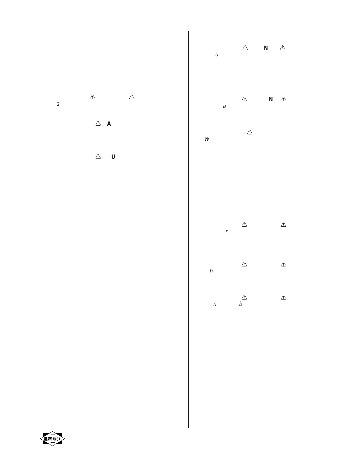
THEORY OF OPERATION
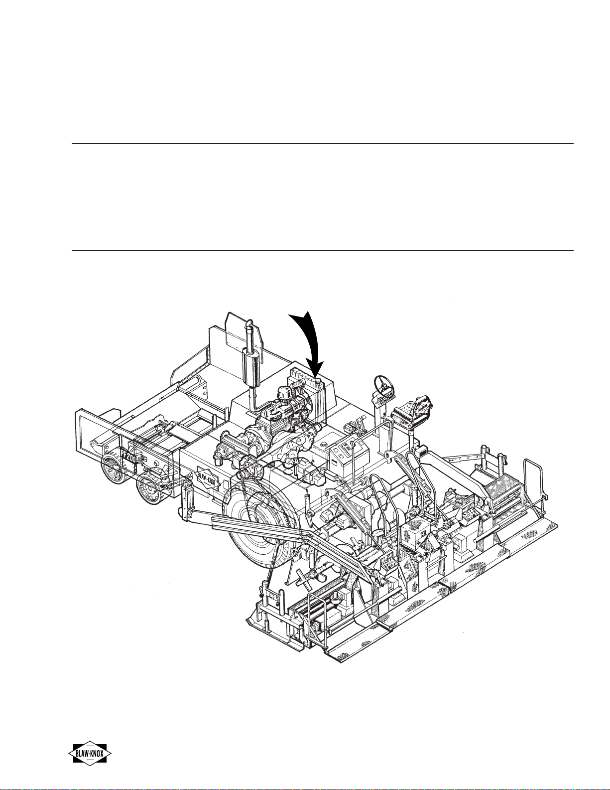
DRIVE TRAIN POWER FLOW
PF-200
This highway class paver/finisher is powered by either
a Cummins or a John Deere 6-cylinder diesel engine
(1)*. Power is delivered through a PTO clutch (2)* and
short coupled drive shaft (3)* to a pump drive box (4).
Traction drive power is hydrostatically transmitted from
the variable displacement traction drive pump (5)* to
the fixed displacement, traction drive motor (6)*. All
early PF-200's (before ser. 20013-01) have (EDC)
electric displacement control of the traction drive pump
from the operator's consoles. Beginning with the PF-
200B's, (beg. ser. 20013-01) the traction pump dis-
placement is mechanically controlled (MDC) through
linkage from the operator's consoles. The traction
motor drives an electric/hydraulic shifted 3-speed
transmission (7)* for speed reduction and selection.
From the transmission, mechanical power is transferred
by another short coupled drive shaft (8)* to the electri-
cally shifted, 2-speed, drive axle (9)*. Roller type
traction drive chains transfer power from each end of
the axle to the two drive wheels (10).
Auger-conveyor drive power is hydrostatically transmit-
ted from the electrically controlled, variable displace-
ment L.H. and R.H. auger-conveyor drive pumps (11)*
(some early model PF-200 pavers may have ON/OFF
pumps) to separate conveyor drive (12)* and auger
drive (13)* L.H. and R.H. motors. The auger function of
each feed system is driven by a single speed motor.
The conveyor speed on either or both sides, can be
changed from HI to LO speed in relation to the respec-
tive auger. The auger motors are fixed displacement
and the conveyor motors are dual displacement for HI-
LOW operation. Mechanical power from the L.H. and
R.H. conveyor motor/planetaries is transferred through
the auger-conveyor drive chain case (14) to the respec-
tive conveyors (15). Mechanical power from the L.H.
and R.H. auger motors/planetaries is transferred
through the chain case to the respective augers (16).
Optional Front Wheel Assist power is hydrostatically
transmitted from the FWA Pump (5A) to the FWA Motor
(6A). ON-OFF function of FWA is controlled by a
separate elect./hyd. bypass valve.
* Specific model numbers of vendor supplied compo-
nents for various series of machines are covered in
the vendors list in the appendix.
1.
2.
3.
4.
5.
5A.
6.
1
25A
34
5
6A
6A
6
7
8
9
10
11 12
17
13
14
Engine
PTO Clutch
Drive Shaft
Pump Drive Box
Traction Drive Pump
Front Wheel Assist Pump
(Optional)
Traction Drive Motor
Conveyor Drive Motors
Auger Drive Motors
Auger/Conveyor Chain Case
Conveyors
Augers
General Purpose Pump (Moves to
outside if opt. FWA is installed.)
12.
13.
14.
15.
16.
17.
BK-14
15
16
11
6A.
7.
8.
9.
10.
11.
Front Wheel Assist Motor
(Optional)
3-Speed Transmission
Drive Shaft
2-Speed Drive Axle
Drive Wheels
Auger/Conveyor Pumps
Drive Train Highway Class Paver/Finishers
A-5
shaft (8)* to the electrically shifted, 2-speed, drive axle
(9)*. Roller type traction drive chains transfer power
from each end of the axle to the two drive wheels (10).
Auger/conveyor drive power is hydrostatically trans-
mitted from the electrically controlled, variable displace-
ment, L.H. and R.H. auger/conveyor drive pumps (11)*
(some early model PF-172 pavers may have ON/OFF
pumps) to independent L.H. and R.H. auger/conveyor
drive motors (12). Mechanical power from the L.H. and
R.H. auger/conveyor drive motors/planetaries is
transferred through the chain cases (13) to the respec-
tive conveyors and augers (15).
Optional Front Wheel Assist power is hydrostatically
transmitted from the FWA Pump (5A) to the FWA Motor
(6A). ON-OFF function of FWA is controlled by a
separate elect./hyd. bypass valve.
* Specific model numbers of vendor supplied compo-
nents for various series of machines are covered in
the vendors list in the appendix.
PF-171 & PF-172
The PF-171 highway class paver/finisher is powered by
a Cummins 4-cylinder diesel engine (1)*. The PF-172
highway class paver/finisher is powered by either a
Cummins or a John Deere 4-cylinder diesel engine (1)*.
Power is delivered through a PTO clutch (2)* and short
coupled drive shaft (3)* to a pump drive box (4).
Traction drive power is hydrostatically transmitted from
the variable displacement, traction drive pump (5)* to
the fixed displacement, traction drive motor (6)*. All
early PF-171's (before ser. 17111-01) & PF-172's
(before ser. 17209-01) have (EDC) electric displace-
ment control of the traction drive pump from the
operator's consoles. Beginning with the PF-171A's
(beg. ser. 17111-01) & PF-172B's, (beg. ser. 17209-01)
the traction pump displacement is mechanically con-
trolled (MDC) through linkage from the operator's
consoles. The traction motor drives an electric/hydraulic
shifted 3-speed transmission (7)* for speed reduction
and selection. From the transmission, mechanical
power is transferred by another short coupled drive
12
13
BK-15
12
15
19
10 8
6
7
25A
11
11
35416
14
1.
2.
3.
4.
5.
5A.
6.
6A.
7.
8.
Engine
PTO Clutch
Drive Shaft
Pump Drive Box
Traction Drive Pump
Front Wheel Assist Pump (Optional)
Traction Drive Motor
Front Wheel Assist Motor (Optional)
3-Speed Transmission
Drive Shaft
2-Speed Drive Axle
Drive Wheels
Auger/Conveyor Pumps
Auger/Conveyor Drive Motors
Auger/Conveyor Chain Case
Conveyors
Augers
General Purpose Pump (Moves to
outside if opt. FWA is installed.)
9.
10.
11.
12.
13.
14.
15.
16.
6A
6A

Highway Class Paver/Finishers Drive Train
A-6
PF-510
The highway class paver/finisher is powered by either a
Cummins or a John Deere 6-cylinder diesel engine (1)*.
Power is delivered through a PTO clutch (2)* and short
coupled drive shaft (3)* to a pump drive box (4).
Traction drive power is hydrostatically transmitted from
the variable displacement L.H. and R.H. traction drive
pumps (5)* to the L.H. and R.H. traction drive motors
(6)*. All PF-510's have independent L.H. and R.H.
(MDC) mechanical displacement control of respective
traction drive pumps through linkage from the operator's
consoles. These motors are each mounted on electric/
hydraulic shifted 3-speed transmissions (7)* for speed
reduction and selection. From the transmissions,
mechanical power is transferred by universal joints (8)*
to a reduction transmission drop box (9) on each side of
the machine. A track drive sprocket on the output shaft
of each drop box drives the track (10).
The track systems are kept properly tensioned auto-
matically by track tension cylinders (11)* forcing the
front take-up wheel assemblies (12) forward. The
general purpose pump (13)* provides 1800 psi pressure
through a manifold and check valve assembly to the
track tension cylinders on each side of the machine.
This pressure keeps the cylinder extended and the
track systems tight by pushing the front take-up wheel
forward whenever the engine is running. Cylinder
pressure is maintained by the check valve when the
engine is off. During operation, if slack is required in
either track when going over large obstructions or
passing solid materials through the drive sprocket and
bogies, the track tension cylinder retracts. As pressure
on the cylinder increases from an obstruction, a hydrau-
lic relief valve will bypass hydraulic pressure to the
cylinder at 3500 psi (24,129 kpa, 241 bar). When the
obstruction has cleared, the relief valve will reset,
retensioning the track.
Auger/conveyor drive power is hydrostatically trans-
mitted from the electrically controlled, variable displace-
ment, L.H. and R.H. auger/conveyor drive pumps (14)*
to independent L.H. and R.H. auger/conveyor drive
motors (15)*. Mechanical power from the L.H. and R.H.
auger/conveyor motors planetaries is independently
transferred through the auger/conveyor drive chain
case (16) to the respective conveyors (17) and augers
(18).
* Specific model numbers of vendor supplied compo-
nents for various series of machines are covered in
the vendors list in the appendix.
15
16
BK-16
15
9
10
9
13
10
12 11
17
678 18
1
2
3
4
18
876
514 14
1.
2.
3.
4.
5.
6.
7.
8.
9.
Engine
PTO Clutch
Drive Shaft
Pump Drive Box
Traction Drive Pump
Traction Drive Motor
3-Speed Transmission
Drive Shaft
Reduction Transmission Drop Box
10.
11.
12.
13.
14.
15.
16.
17.
18.
Drive Track
Track Tension Cylinder
Front Tack-Up Wheel
General Purpose Pump
Auger/Conveyor Pumps
Auger/Conveyor Drive Motors
Auger/Conveyor Chain Case
Conveyors
Augers
5

Drive Train Highway Class Paver/Finishers
A-7
COMPONENT INTERVAL
Hydraulic fluid (check level) Daily
Engine oil (check level) Daily
Engine air filter (check) Every 240 hours
Short coupled drive shafts Every 240 hours
(grease)
Engine oil and filter Every 240 hours
(change both)
Front wheel king pins Weekly
(grease) (Wheeled Machines)
Drive wheel spindles Weekly
(grease) (Wheeled Machines)
Parking brake (grease) Quarterly
Hydraulic fluid Yearly
Hydraulic filters Yearly
(Change filters after first 50 Yearly
hours)
Front wheels (repack with Yearly
grease) Wheeled Machines)
Pump drive box (change Yearly
fluid)
Transmission (change fluid) Yearly
Engine fuel filter (change) Yearly
Engine PTO and clutch Yearly
(grease)
Differential in axle (change Yearly
fluid)
Bogie pivot bearings Weekly
(grease) (PF-510 only)
Traction cases (change fluid) Yearly
(PF-510 only)
Note: Specifications and fluid capacities for each
model are covered in the front section of this manual.
Refer to Section C in each models Operator's Manual
for routine Service Procedures and locations on the
machine.
• Inspect the engine compartment: Pay particular
attention to fuel and cooling system components,
starter, alternator, oil system, electrical wiring and
engine mounts.
• Inspect all breathers (on transmissions and
planetaries) for clogging.
After inspection, it is important to perform basic preven-
tive maintenance as shop policy. Completely lubricating
the machine, and, checking and refilling battery, engine
oil, hydraulic and cooling system levels is recom-
mended as a minimum.
SYSTEM MAINTENANCE AND
SERVICE
The drive train is one of the most important systems of
the machine. To ensure machine availability, preven-
tive maintenance must be performed before work
begins. Preventive maintenance begins with inspection.
Systematic inspection may reveal damage that, if not
corrected, may result in serious damage or failure. Any
problems revealed during pre-service inspection must
be reported to the shop foreman or service manager.
The following is a list of inspection criteria that should
be performed whenever the machine is serviced.
• Keep it clean: Dirt, grease, oil and debris only get in
the way and may cover up a serious problem.
Clean as you work and as needed. Use cleaning
solvent to clean metal surfaces and soap and water
to clean rubber or plastic material.
• Bolts, nuts and screws: Check that they are not
loose, missing, bent or broken. Look for chipped
paint, bare metal or rust around bolt heads. Tighten
any that are loose and torque to specification.
• Traction drive chains: Keep chains properly ad-
justed. Properly adjusted chains will produce
maximum service life.
• Welds: Look for loose or chipped paint, rust, or
gaps where parts are welded together. If you find a
bad weld, report it to your supervisor immediately.
• Electric wires and connectors: Look for cracked or
broken insulation, bare wires and loose or broken
connectors. Tighten loose connections and make
sure wires are in good condition.
• Hoses and fluid lines: Look for wear, damage and
leaks. Make sure clamps and fittings are tight. Wet
spots show leaks, of course, but a stain around a
fitting or connector can also mean a leak. If a leak
comes from a loose fitting or connector, tighten it. If
something is broken or worn out, either correct it or
report it to your supervisor. Tighten all hoses and
fittings before putting machine in service.

Highway Class Paver/Finishers Drive Train
A-8
Before taking any action to correct a possible malfunc-
tion, follow these rules:
• Question the operator if possible to obtain any
information that might help determine the cause of
the problem.
• Never overlook the chance that a problem could be
of simple origin. The problem could be corrected
with minor adjustments.
• Use all senses to observe and locate troubles.
• Use test instruments or gauges to help you deter-
mine the isolate problems.
• Always isolate the system where the malfunction
occurs and then locate the defective component.
DRIVE TRAIN
TROUBLESHOOTING
The troubleshooting guides in this section list the
common malfunctions which may be found during the
operation or maintenance of the machine. You should
perform the test/inspections and corrective actions in
the sequence listed.
This manual cannot list all malfunctions that may occur,
nor all tests or inspection and corrective actions. If a
malfunction is not listed or it is not corrected by the
listed corrective actions, notify your supervisor.
Each malfunction symptom is followed by yes/no
step(s) that should be taken to determine the cause and
the corrective action that must be taken to remedy the
problem.

Drive Train Highway Class Paver/Finishers
A-9
DRIVE TRAIN TROUBLESHOOTING (CONTINUED)
ENGINE WILL NOT CRANK
(All main switches ON)
Problem Solution
1. Traction levers not in neutral Check control levers must both be in
neutral/Reposition.
2. Left-Right Switch (on center console) Check operating position/Reposition.
3. Low or dead battery Check voltage at terminals/Charge or replace.
Check electrolyte level/Fill & charge.
4. Poor battery connections Check terminal connections/Clean & tighten.
5. Poor engine ground Check ground cable/Clean & tighten.
6. Poor starter motor connections Check starter connections/Clean & tighten.
7. Open electrical circuit Check for wire off of any terminal in circuit/Reconnect.
8. Faulty "neutral start" limit switches Check position, voltage & continuity/Reposition
(on traction pump or inside of op. consoles) switch(es) (see number 1) or replace.
9. Faulty starter motor solenoid Check voltage & function/Replace.
10. Faulty "starter" relays (on starter) Check voltage & continuity/Replace.
(inside of center consoles)
11. Faulty "main" power relay (inside of center console) Check voltage & continuity/Replace.
12. Faulty "motion" relay (inside of center console) Check voltage & continuity/Replace.
13. Faulty governor switch (on center console) Check position, voltage & continuity/Change position
or replace.

Highway Class Paver/Finishers Drive Train
A-10
DRIVE TRAIN TROUBLESHOOTING (CONTINUED)
ENGINE CRANKS BUT WILL NOT START
(All main switches ON)
Problem Solution
1. No fuel in tank Check tank/Fill.
2. No fuel to engine Check voltage at engine injection pump.
Check fuel filter(s)/Replace.
Check fuel lines to engine/Clean.
Check fuel pump voltage & function/
Repair or replace.
Check injectors & injection fuel lines/
Clean.
3. Contaminated fuel in tank Check tank/Drain & refill.
4. Incorrect fuel in tank Check tank/Drain & refill.
5. Slow cranking engine Cold weather/Release clutch.
Check battery voltage/Charge or replace.
Check battery electrolyte level/
Fill & charge.
Check battery terminals/Clean & tighten.
6. Other engine problems * See Engine Manual.
* See John Deere Engine Operator's Manual, OMRG18293, pages 68-76.
* See Cummins Engine Operator's Manual, 3810205, page T1-T33.
Note: The above manuals cover additional less likely problems.

Drive Train Highway Class Paver/Finishers
A-11
DRIVE TRAIN TROUBLESHOOTING (CONTINUED)
ENGINE RUNS PROPERLY BUT MACHINE WILL NOT MOVE -
FORWARD OR REVERSE
Problem Solution
1. No hydraulic fluid in tank Check hydraulic tank dip stick/Fill.
2. Clutch not engaged Check lever/Engage or adjust.
3. Hydraulic filter plugged Check filter/Replace.
4. High-Low axle not engaged (wheel driven) Check shift unit/Repair or replace.
5. Open traction electrical circuit Check for wire off of any terminal in circuit/Reconnect.
6. Traction pump(s) not stroking (MDC machine only) Check linkage/Repair or replace.
Check MDC on pump(s)/Repair or replace.
Check charge pressure/Repair or replace.
7. Traction pump not stroking (EDC machines only) Check manual override (red plastic screw) on pump EDC.
Check pump solenoid coil voltage & continuity/
Replace.
Check voltage outputs of lever control(s) under load/
Replace control lever complete (see elec. section
for details).
Check charge pressure/Repair or replace.
8. Transmission not engaged Check inside under cover/Repair.
9. Broken drive chain(s) (wheel driven) Check chains/Repair or replace.
10. Broken axle or differential (wheel driven) Check for rotating input yoke & no rotation at output
sprockets/Repair or replace.

Highway Class Paver/Finishers Drive Train
A-12
DRIVE TRAIN TROUBLESHOOTING (CONTINUED)
MACHINE WILL NOT STEER PROPERLY - TRACK DRIVEN
Problem Solution
1. Equal traction lever movement does not produce Check linkage from levers to traction pumps/Adjust.
straight travel Check both L.H. & R.H. traction pumps for equal
charge pressure/Adjust.
Check either L.H. or R.H. brake not released/Adjust,
repair or replace.
Check both sides of the trans. shift control valve on the
hydraulic tank for proper function/Replace coil(s)
or repair.
Check both L.H. & R.H. trans. are in same gear/Repair
or replace shift cap.
Check both L.H. & R.H. trans. shift hydraulic circuits for
leaks/Repair.
MACHINE WILL NOT STEER PROPERLY - WHEEL DRIVEN
Problem Solution
1. One foot brake not released Check brake calipers on ends of axle/Repair.
Check master cylinder/Repair.
2. Steering linkage not greased Check linkage (below hopper)/Grease.
3. Steering linkage bent or worn Check tie rods (below hopper)/Straighten rods,
adjust or replace rod ends.
4. Faulty steering unit(s) Try other operator's console/Repair or replace.
5. Steering hydraulic circuit Check all hoses, tubes & fittings/Repair or replace.
6. Faulty steering cylinders Check for piston leak-by with cylinder fully extended
and retracted and alternate hoses disconnected/
Replace o-ring seals.
7. Worn king pin bearings Check for free pivot movements of wheels with
steering cylinders disconnected/Replace
bearings.
8. Worn wheel spindle bearings Check for free, smooth rotation of wheels/Replace
bearings.

Drive Train Highway Class Paver/Finishers
A-13
DRIVE TRAIN TROUBLESHOOTING (CONTINUED)
FWA (FRONT WHEEL ASSIST) DOES NOT OPERATE
Problem Solution
1. FWA switch is ON but bogie wheels do not turn Check that governor switch is in PAVE, trans. switch is
in LOW & traction lever is pushed FORWARD/
correct positions.
Check manual override on bypass valve.
Check voltage & continuity of bypass valve coil/
Replace coil.
Check voltage & continuity of FWA pump control coil/
Replace coil.
2. Open electrical circuit Check for wire off of any terminal in circuit/Reconnect.
3. Faulty "motion" limit switch (EDC machine only) Check voltage & continuity/Replace.
4. Faulty "motion" relay (inside of center console) Check voltage & continuity/Replace.
5. Faulty "governor switch" (on center console) Check voltage & continuity/Replace.
6. Faulty "trans. switch" (on op. consoles) Check voltage & continuity/Replace.
7. Faulty "FWA" switch (on op. consoles) Check voltage & continuity/Replace.
8. Inadequate charge pressure Check at pump/Repair or replace pump.
PARKING BRAKE WILL NOT RELEASE
Problem Solution
1. Brake does not release when switch is OFF Check manual override on control valve.
Check voltage & continuity of control valve coil/
Replace coil.
2. Clutch is not engaged Check clutch lever/Engage or adjust.
3. Air in brake line Check at caliper bleeder screw/Bleed line.
4. Leak in brake line Check hose & fittings/Repair or replace.
5. Inadequate brake(s) clearance Check caliper for 0.012 (0.035 mm) running clearance
all around when released/Adjust, repair or
replace.
6. Open electrical circuit Check for wire off of any circuit terminal/Reconnect.
7. Faulty brake switch(es) (on op. console) Check voltage & continuity at switch/Replace.
8. Faulty "neutral start" limit switch Check voltage & continuity/Replace.
(MDC machines only)
9. Faulty "motion" limit switch (EDC machines only) Check voltage & continuity/Replace.

Highway Class Paver/Finishers Drive Train
A-14
E
NGINE
A
SSEMBLY
This procedure covers:
✓Removal Inspection/Specification ✓Installation
Disassembly Assembly ✓Adjustments
Special Cleaning Component Test ✓Equipment Preparation
Machine Set-up Special Tools Fabricated Tools
• Engine housing removed. ✓None ✓None
• Battery disconnected.
• Air cleaner assembly removed.
• Machine blocked to prevent movement.
• Catch container for oil (5 gal., 20 L).
• Catch container for coolant (10 gal., 40 L).
• Throttle cylinder removed.

Drive Train Highway Class Paver/Finishers
A-15
ENGINE ASSEMBLY
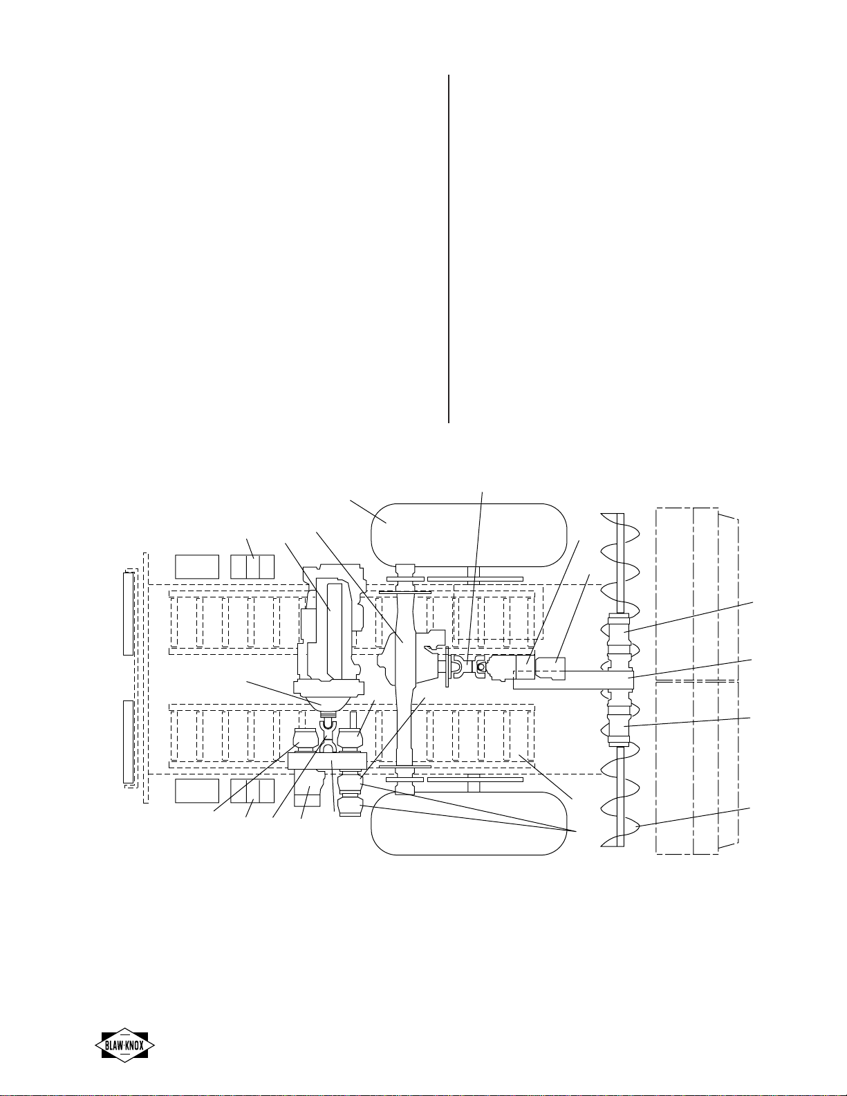
REMOVAL
Step 1:
Drain engine oil.
a. Open access door on right side of machine.
b. Remove oil drain cap from drain line (1).
c. Allow oil to drain into catch container.
d. After oil has drained, install oil drain cap.
1
0760-49A
Step 2:
Drain radiator coolant.
a. Open access door on right side of machine.
b. Loosen radiator cap (2).
2
0760-21B
c. Open radiator drain petcock (3).
d. Allow radiator coolant to drain into catch con-
tainer.
e. After coolant has drained, close radiator drain.
3
1144-57
Step 3:
Disconnect drive shaft.
a. Remove drive shaft cover bolts.
b. Remove drive shaft cover (4).
4
0760-29A
c. Remove clutch side flange mounting bolts (bolts
have loctite on them) from drive shaft (5).
d. For access to all bolts, disengage manual clutch
(6) and turn drive shaft.
NOTE
Engage manual clutch when removing drive
shaft U-bolts.
6
5
0760-27B
Highway Class Paver/Finishers Drive Train
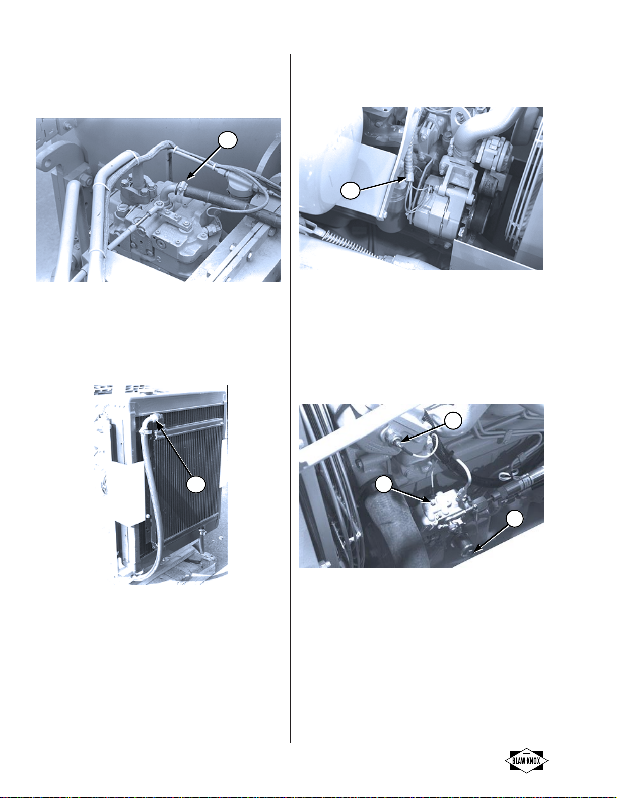
A-16
Step 4:
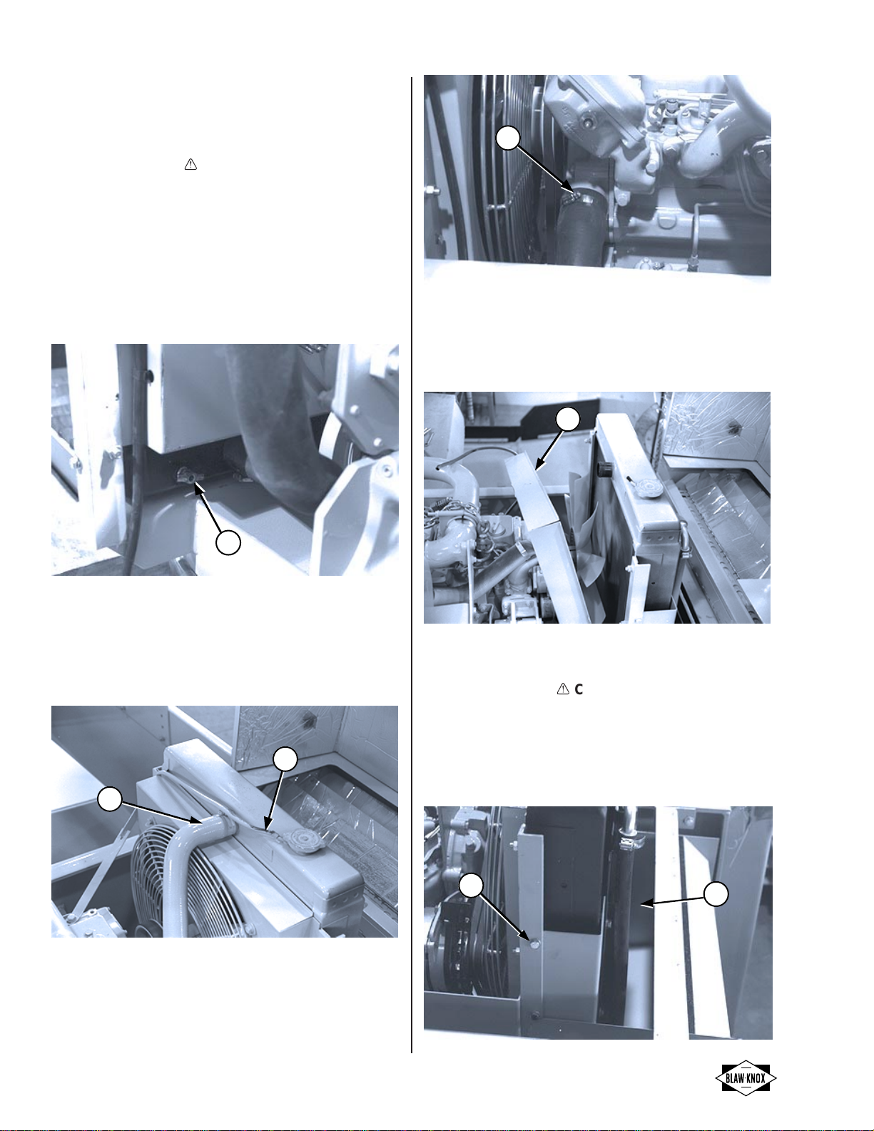
Disconnect oil cooler inlet and outlet hoses.
a. Remove clamps at traction pump and remove
hose (7).
7
1144-08C
b. Mark, plug and cap traction pump outlet hose
and pump fitting.
c. Lay outlet hose along side of engine.
d. Loosen clamp (8) on inlet hose on top of oil
cooler and remove hose.
8
0718-97A
e. Mark, plug and cap inlet hose and oil cooler
fitting.
Step 5:
Disconnect electrical wiring harness.
a. Disconnect wires (9) from alternator.
9
0760-34A
b. Cut tie straps holding wiring harness to engine.
c. Remove clamps holding wiring harness to clutch
housing.
d. Disconnect wire on water temperature sensor
(10).
e. Unplug fuel shut off wire (11) from engine.
f. Disconnect engine oil pressure switch (12).
g. Remove starter wire.
10
11
12
1144-66A
Drive Train Highway Class Paver/Finishers
A-17
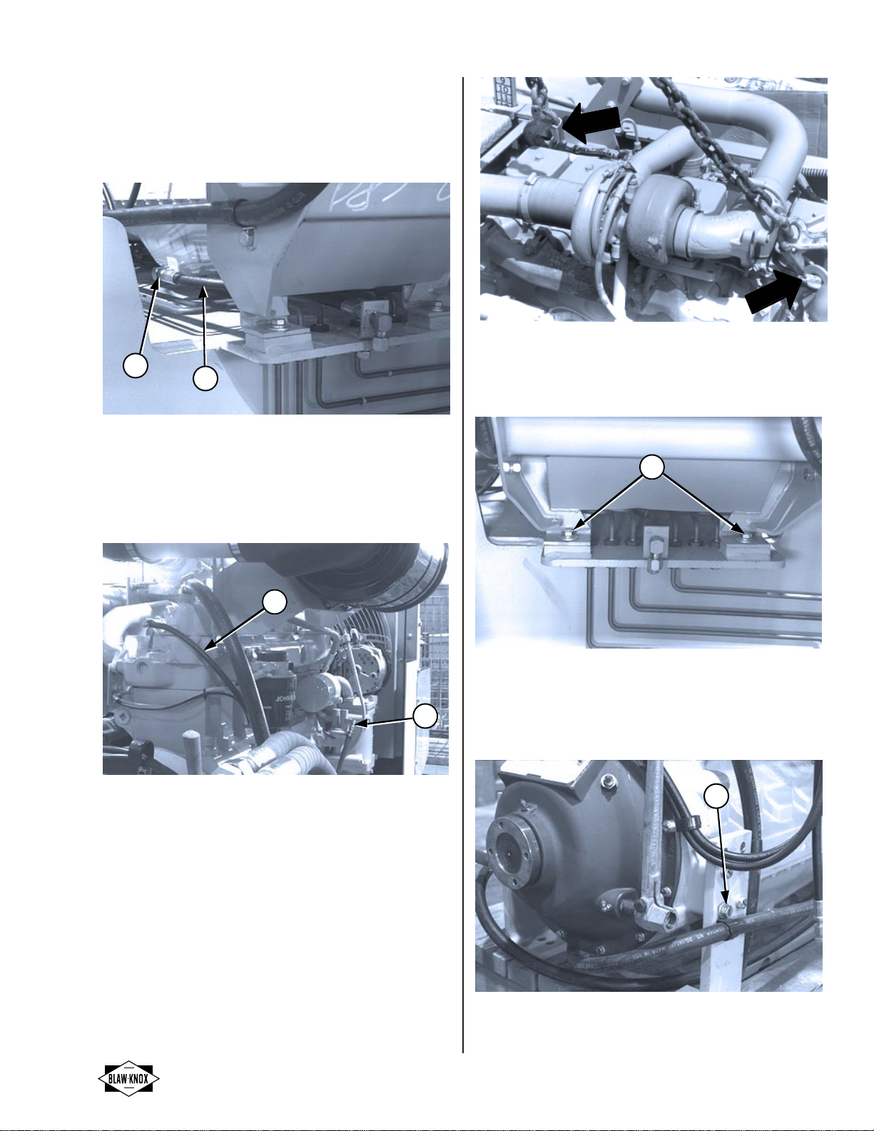
Step 6:
Remove engine oil drain line.
a. Remove oil drain clamp (13).
b. Pull drain line (14) out of drain hole and keep
line with engine.
13 14
1144-70
Step 7:
Remove fuel pickup (15) and return (16) lines.
a. Loosen clamps on fuel lines.
b. Pull fuel lines off of fittings.
16
15
1144-71
Step 8:
Remove engine.
a. Secure chain to lifting eyes and attach to hoist.
Engine weighs approximately 500 lbs. (230 kg).
Take up slack.
b. Remove engine mounting bolts (17) on the right
side by the oil drain.
17
1144-72
c. Remove mounting bolts on left side of engine on
front and rear brackets (18).
d. Lift engine out.
18
1144-61
BK-16
7

Highway Class Paver/Finishers Drive Train
A-18
REPAIRS OR ADJUSTMENTS
Repairs or adjustments can be found in the particular
engine manual. Refer to Appendix A-1 for a listing of
available engine publications.
INSTALLATION
Install engine by reversing removal procedures.
EQUIPMENT PREPARATION
Step 1:
Install throttle cylinder (19) on engine (See
"THROTTLE CYLINDER" for installation
procedures.)
19
0760-40C
Step 2:
Install air cleaner assembly (20) on engine (See
"AIR CLEANER ASSEMBLY" for installation
procedures.
20
0760-20A
Step 3:
Fill engine with oil.
Step 4:
Fill radiator with proper coolant mixture.
Step 5:
Check hydraulic tank fluid level.
Step 6:
Connect battery.
Step 7:
Start engine and allow to warm-up to operating
temperature.
Drive Train Highway Class Paver/Finishers
A-19
R
ADIATOR
This procedure covers:
✓Removal Inspection/Specification ✓Installation
Disassembly Assembly Adjustments
Special Cleaning ✓Component Test ✓Equipment Preparation
Machine Set-up Special Tools Fabricated Tools
• Engine housing raised. ✓Cooling system ✓None
• Machine blocked to prevent movement. Pressure tester
• Battery disconnected.
• Coolant Catch container for coolant (10 gal., 40 L).
Highway Class Paver/Finishers Drive Train
A-20
RADIATOR
REMOVAL
!
CAUTION
Radiator contents under pressure. Remove cap
slowly to relieve pressure within the system.
Step 1:
Drain radiator.
a. Remove radiator cap.
b. Open radiator drain petcock (1) at bottom of
radiator.
c. Drain radiator into proper container.
1
1144-57A
Step 2:
Disconnect top hoses.
a. Loosen clamps on hoses (2 and 3).
b. Pull hoses off of radiator.
2
3
0760-31A
Step 3:
Remove lower hose.
a. Loosen clamp on hose (4).
b. Pull hose off of engine.
4
1144-63
Step 4:
Remove fan guard and shroud.
a. Remove shroud mounting bolts.
b. Pull shroud and fan guard (5) back.
5
0760-50A
Step 5:
Remove radiator.
!
CAUTION
Do not damage radiator during removal.
a. Remove radiator mounting bolts.
b. Attach lifting device, or have two people lift out.
c. Loosen oil cooler bolts (6) so radiator clears oil
cooler (7).
d. Carefully pull radiator up and out.
67
1144-076
Table of contents


