Blaze AHRS-2 User manual

Blaze AHRS-2
Blaze AHRS-4
Blaze MAG-2
AHRS-2: Artificial Horizon and Magnetic
Compass indicator
AHRS-4: Self Contained Artificial Horizon,
Magnetic Compass indicator
MAG-2: Magnetic Compass Indicator
perating Manual – English 1.06

Blaze AHRS-2 / AHRS-4 / MAG-2 perating Manual Page 2
Introduction
The AHRS-2 / AHRS-4 / MAG-2 is a 3 1/8” (80mm) sunlight rea able color isplay instrument provi ing a isplay for an
artificial horizon reference system (AHRS), an a vance igital compass, or both epen ing on which sensor packages is
connecte .
The AHRS-2 is an attitude display for the external MGL-Avionics SP-7 attitude sensor package. The AHRS-2 re-
quires the MGL-Avionics SP-6 compass sensor package to display heading.
The AHRS-4 is a self contained attitude display with built in sensors. The AHRS-4 does not require the MGL-
Avionics SP-7 sensor package in order to display the attitude, but requires the MGL-Avionics SP-6 compass sen-
sor package to display heading. The AHRS-4 can output CAN bus messages to emulate the MGL Avionics SP-7
sensor package.
The MAG-2 is a compass display for the external MGL-Avionics SP-6 compass sensor package.
The AHRS-2 / AHRS-4 / MAG-2 can be setup to isplay the following:
•Compass with optional slip in icator (requires MGL Avionics SP-6 sensor package)
•Horizon with optional slip, turn in icator & G-Force (requires the MGL Avionics SP-7 if using the AHRS-2)
•Turn an bank in icator (requires the MGL Avionics SP-7 if using the AHRS-2)
•Combine compass an horizon isplay with bank in icator, optional slip in icator & G-Force (requires MGL
Avionics SP6 & the Avionics SP-7 if using the AHRS-2)
1 Features
•Large 2.6” high resolution 320x240, IPS (fully viewa le in all directions), sunlight reada le color LCD dis-
play
• AHRS-2 (Artificial horizon reference system (AHRS) display unit with slip indication, turn and bank and G-
Force indication), requires the MGL Avionics SP-7 sensor packages
• AHRS-4 (Artificial horizon reference system (AHRS) display unit with slip indication, turn and bank and G-
Force indication) complete with built in attitude sensors. The AHRS-4 does not require the MGL Avionics
SP-7 sensor package to display attitude.
• Advanced magnetic compass with a course steering feature and slip indication
• Can be setup as an individual compass display, artificial horizon or both
• The AHRS-2 / AHRS-4 / MAG-2 is connected to the AHRS / Compass sensor packages by a simple CAN
bus interface. This allows for the optimum placement of the sensor packages in the aircraft
• More then one AHRS-2 / AHRS-4 / MAG-2 unit can be connected onto the CAN bus. This allows the com-
pass, artificial horizon and the turn and bank indicator to be displayed on different units
• G-Force indicator (MGL Avionics SP-7 required if using the AHRS-2)
• Built in NMEA GPS Viewer
• Automatic or manual magnetic variation calculation
• Sunset and sunrise time display
• Displays time & date, GPS altitude, S G, C G, latitude and longitude when using an external NMEA com-
patible GPS receiver
• Includes a RS232 serial output for interfacing to external equipment e.g dataloggers etc.
• The AHRS-4 can output CAN bus messages to emulate the MGL Avionics SP-7 sensor package.
• Standard 3 1/8” (80mm) aircraft enclosure (can be front or rear mounted)
• The LED backlight can automatically adjust to the ambient light, or it can be manually adjusted in the
menu system
• Rotary control plus 2 independent buttons for easy menu navigation and user input
• An external output activates when a high alarm condition has been reached
• Wide input supply voltage range of 8 to 30V DC with built in voltage reversal and over voltage protection
for harsh electrical environments
• 1 year limited warranty

Blaze AHRS-2 / AHRS-4 / MAG-2 perating Manual Page 3
2 Layout
2.1 AHRS-2 / AHRS-4 Layout
2.2 MAG-2 Layout
F2 / Down Button:
Menu System: Softkey button
Fast level function
Sunlight readable color graphic display:
The backlight can automatically a just
to the ambient light or it can be manually
a juste in the menu system
Rotary Control (Up/Down) & Enter Button:
Press the rotary control uring the normal isplay screens to access the menu system.
Rotate anti/clockwise for up/ own menu scrolling. During normal mo e turning the rotary control
anti/clockwise will scroll through the main isplays (Artificial horizon, compass an turn an bank
in icator).
F1 / Up Button:
Menu System: Softkey button
Pitch level function
3 1/8” (80mm) enclosure.
Can be front or rear mounte
Rotary Control (Up/Down) & Enter Button:
Press the rotary control uring the normal isplay screens to access the menu system.
Rotate anti/clockwise for up/ own menu scrolling.
F1 / Up Button:
Menu System: Softkey button
Enable coarse steering isplay
F2 / Down Button:
Menu System: Softkey button
Enable the reverse coarse isplay
3 1/8” (80mm) enclosure.
Can be front or rear mounte
Sunlight readable color graphic display:
The backlight can automatically a just
to the ambient light or it can be manually
a juste in the menu system
Ambient light sensor
Ambient light sensor

Blaze AHRS-2 / AHRS-4 / MAG-2 perating Manual Page 4
3 Main Displays
The AHRS-2/4 can be set up to show 5 ifferent isplay screens. Turning the rotary control either clockwise or anti-clock-
wise allows you to select the operation of the AHRS-2 / AHRS-4 as an artificial horizon with mini compass an turn an
bank in icator, a turn an bank in icator, a igital compass, or as a NMEA GPS viewer
The MAG-2 only isplays the compass an GPS isplays.
Note: If you have purchase the artificial horizon an compass sensor packages with two or three AHRS-2 / AHRS-4 /
MAG-2 isplays, it is possible to setup either of the units to isplay either the artificial horizon, turn an bank in icator or
the compass.
3.1 Artificial Horizon with Compass
Pitch level function
Shoul your aircraft fly “nose up” or “nose own” ue to trim, then you can press the F1 key to level the pitch as isplaye
on the horizon.
3.2 Turn and Bank Indicator
Slip indicator
A “step on the ball” slip in icator can be enable to appear below the horizon an compass isplays. The source of infor-
mation for this in icator is erive from the accelerometer aligne with the pitch axis of the aircraft, i.e. the acceleration
forces acting in the irection of the wings.
G-Force isplay
10 egree pitchbars
5 egree pitchbars
Slip in icator can be turne on or off in the menu system
Estimate Horizon
Magnetic or true hea ing rea ing
(compass can be switche off
in the menu system)
Mini turn an bank in icator
(can be switche off in the
menu system)
Slip in icator
Marker escription

Blaze AHRS-2 / AHRS-4 / MAG-2 perating Manual Page 5
Fast level function
Press the F2 key shoul the horizon isplay be topple (i.e. in icating incorrectly by a large amount) ue to excessive
maneuvering or by excee ing the maximum bank, pitch or yaw rates. This will in icate to the instrument that you are fly-
ing straight an level an that gravity tracking may be accelerate to ensure rapi realignment of the horizon.
Extended range of operation
Please see the correspon ing MGL sensor ocumentation for maximum rate specifications.
Depen ing on con itions maximum rates may reach 180 egrees per secon . No caging of the electronic gyro system is
require uring excessive maneuvering, unlike systems base on mechanical gyros. Simply correct the horizon when you
are finishe or let the horizon right itself which will happen uring straight an level flight.
Message isplaye when the maximum bank, pitch or yaw rates have been excee e
3.3 Digital Compass
3.3.1 Compass Tape
The igital compass tape can be isplaye in 3 ifferent ways. The way the compass is isplaye can be setup in the
menu system un er “COMPASS SETUP”
Numeric compass display
The hea ing tape shows hea ings as numbers in egrees.
Mixed compass display
The hea ing tape shows hea ings as number in egrees except for the four major
car inal points which are shown as N, S, E an W.
Cardinal compass display
The hea ing tape shows hea ings as major an interme iate car inal points: N, NE, E,
SE, S, SW, W an NW.
Magnetic (M) or true
(T) North in icator
Slip in icator can be turne on or off in the menu system
Course steering In icator

Blaze AHRS-2 / AHRS-4 / MAG-2 perating Manual Page 6
3.3.2 Heading bug and the course steering indication
To activate the hea ing bug, press the F1 key when the compass isplay is showing.
Press the F1 key again to use the current hea ing as the hea ing bug or use the rotary
control to manually enter a hea ing. Press the F2 key if you want to switch the hea ing
bug off.
The hea ing bug set to 176 egrees. Currently the hea ing equals the course to steer as
shown below the hea ing tape. No course steering in icators are shown.
The current hea ing is 169 egrees; course steering in icators show the nee to steer
slightly to the right to intercept the course.
The current hea ing is 218 egrees; course steering in icators show that a large
correction to the left is require to intercept the course.
Each “>” or “<” equals 2 egrees of hea ing error. To cancel the course steering function, simply press the F1 key again.
3.3.3 The reverse course (from heading) display
Press the F2 key to activate the reverse course isplay. This isplay remains active for
about 5 secon s before reverting back to the normal hea ing isplay.
Blaze AHRS-2 / AHRS-4 / MAG-2 perating Manual Page 7
3.3.4 Heading stability issues
You may fin short term fluctuations of the hea ing occurring. These ten to be very small an are typically less than one
egree. This coul still cause the hea ing to fluctuate occasionally by a single egree. These fluctuations occur naturally
in the earth’s magnetic fiel an can also be cause by nearby electrical equipment such as ra ios, lamps, electronic in -
strumentation or computers, even the ignition systems of engines. The AHRS-2 / MAG-2 has a compass filter setting
which can be set to filter out some of these small fluctuations.
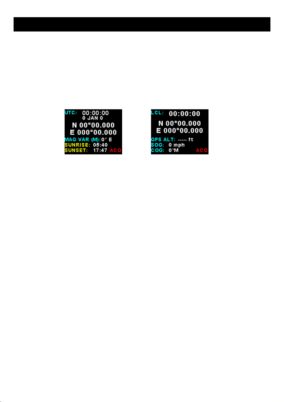
3.4 GPS Viewer
These isplay are active when a NMEA compatible GPS receiver is connecte to the serial port.
The following GPS information is isplaye :
•Time an ate
•Latitu e an Longitu e
•Magnetic variation
•Sunrise an Sunset times
•GPS altitu e
•SOG (Spee over groun )
•COG (coarse over groun )
•GPS fix

Blaze AHRS-2 / AHRS-4 / MAG-2 perating Manual Page 8
4 Menu System
Press the rotary control button uring the normal isplay mo e to enter the menu system. Use the rotary control to navi-
gate through the menu system.
4.1 Exiting the menu system
Press the F1/Up button to exit the menu system when the “EXIT” soft key is shown. All changes ma e uring navigation
of the menu system will be save in non-volatile memory upon exiting. The instrument will not save any changes if you re-
move power before exiting the menu system.

Blaze AHRS-2 / AHRS-4 / MAG-2 perating Manual Page 9
4.2 Horizon Setup
Compass:
Select “ON” if you woul like to see the compass box on the horizon isplay.
Numeric:
Select “ON” if you woul like to see a numeric isplay of bank an pitch angles superimpose on the horizon isplay.
G-Force:
Select “ON” if you woul like to see the G-Force isplaye on the horizon isplay.
Ground :
Select the groun color of the horizon. A selection between "BROWN" ( efault) or "GREEN" can be ma e.
Turn:
Select whether you want the turn in icator to be shown on the horizon isplay screen.
Turn Rate:
Select whether you want the turn an bank in icators to show a 1 min/rotation or 2 min/rotation turn.

Blaze AHRS-2 / AHRS-4 / MAG-2 perating Manual Page 10
Slip:
Select if you woul like to enable the slip in icator to be shown un erneath the horizon isplay. The slip in icator oper-
ates in the same fashion as the well known “step on the ball” in icator in tra itional cockpits.
Note: The slip in icator is always enable in the turn an bank in icator mo e.
Slip Sense:
Select if you want the slip to have a high sensitivity or a low sensitivity setting.
Slip Zero:
This function allows you to set your slip in icator to exactly zero even if your aircraft ten s to fly slightly wing own. The
proce ure is to place the aircraft in a stable, straight an level attitu e uring calm flight con itions an then select this
function. To cancel the correction, place your sensor absolutely horizontal (use a spirit level) an select the function
again.
Speed Unit:
Select the spee unit.
Speed:
Enter the cruising spee of your aircraft. This spee is transmitte to the attitu e sensor for ai ing purposes if the GPS
spee is not available.
Pitch Marker:
This enables or isables the pitch markers on the horizon isplay.
CAN Address:
Select the CAN a ress of the SP-X attitu e sensor.
Pitch Zero:
The pitch zero function must be performe with the AHRS perfectly level. The AHRS will refuse to perform this operation
if the real pitch angle is greater than 10 egrees. Selecting the pitch zero function will zero the pitch, selecting it again will
reset the pitch offset value to 0 egrees.
ank Zero:
The bank zero function must be performe with the AHRS perfectly level. The AHRS will refuse to perform this operation
if the real bank angle is greater than 10 egrees. Selecting the bank zero function will zero the bank, selecting it again will
reset the bank offset value to 0 egrees.
Couple Coeff (AHRS-4 only):
This is a number from 1 to 10. “1” is the efault.
This number etermines how “strongly” the AHRS will force the gyro erive horizon estimate to coinci e with that of the
accelerometer base level calculations which are base on gravity.
“1” causes a very slow correction. This is the normal state an use most often.
“10” is the highest correction spee . This is usually use if the AHRS is use in unfavorable con itions.
Backgroun :
Gyros can only tell you if you are rotating aroun any axis (you have three of them). Gyros cannot tell your attitu e, they
can only tell you how your attitu e is changing.
Accelerometers can tell you your attitu e – but only if you are not accelerating. That inclu es a turn as this involves accel-
eration (constant change of irection). In a ition accelerometers will react to any movement of your aircraft cause by
turbulence etc.
So – basically accelerometers can sometimes tell you your attitu e while gyros can tell you how your attitu e has
change – but with errors as measurements are never 100% accurate – so the longer you rely only on the gyros the
worse it gets.

Blaze AHRS-2 / AHRS-4 / MAG-2 perating Manual Page 11
To a large extent the AHRS can estimate accelerations acting on your aircraft as it knows the aircraft's velocity. This
means it can estimate a reasonably vali attitu e from the accelerometers that is “noisy” even in accelerate flight. For
this to be possible it has to assume how your aircraft moves through space. So it is mostly correct but sometimes not.
The coupling coefficient allows you to tra e between the two.
Usually a panel mounte AHRS is affecte by vibrations from engines (gyros on't like vibrations). This is the largest error
source for a typical AHRS. If your installation suffers from that a higher coupling number may assist as gyro errors are
larger than normal.
If this oes not help you will have to either try an re uce vibrations affecting the panel or install an external AHRS like
the SP-7 or high gra e SP-9. This allows locating the AHRS in a more suitable an protecte area. If the AHRS-4 etects
an external AHRS it will automatically use it. External AHRS is connecte onto the CAN bus.
Tilt Compensate (AHRS-4 only):
This allows installation of the AHRS-4 at angles other than vertical (face). Select this menu item once installation of the
AHRS-4 in icator is complete. The tilt compensation only nee s to be performe once. This allows to set a pitch tilt of the
AHRS, keeping all spee relate items affecting the accelerometers aligne correctly.
Level Calibrate (AHRS-4 only):
This function can be use to level the AHRS. It levels bank an pitch an sets the Z axis (up own) to 1G.
The level calibrate function here MUST be performe with the AHRS perfectly level, i.e. isplay in normal orientation at 90
egrees from the horizontal in both pitch an bank. This function “tweaks” the accelerometer sensor using the Earths
gravity as a reference.
This function takes aroun 10 secon s to execute. Keep the AHRS perfectly still until complete .
Note: The AHRS will refuse to perform this operation if real AHRS bank or pitch angle is greater than 10 egrees.
Reset Gyro ias (AHRS-4 only):
Your AHRS gyros bias point is the point where your gyros report that you are not rotating aroun any axis. Gyro bias may
rift over time as the gyro chip ages. This function resets the bias to the current rea ing an is performe with the aircraft
on the groun , preferably in a hangar with no win rocking the aircraft. The aircraft may be in any attitu e but must remain
perfectly still uring this proce ure. After you activate this proce ure it takes about 30 secon s to complete it. Keep the
aircraft perfectly still uring this operation.
CAN TX AHRS (AHRS-4 only):
Select “ON” to output the MGL Avionics SP-7 CAN bus messages. This gives the AHRS-4 the ability to emulate the MGL
Avionics SP-7 sensor package.

Blaze AHRS-2 / AHRS-4 / MAG-2 perating Manual Page 12
4.3 Compass Setup
Display:
Select the style of the compass tape as in section isplay mo e as escribe in section 3.3 above
Heading:
Select whether you woul like the instrument to isplay magnetic or true hea ing. If you select true hea ing, you nee to
enter the correct magnetic variation for your location. You can fin your local variation on aeronautical or maritime charts.
The hea ing isplays will be augmente with °M or °T epen ing on the mo e you have selecte .
Mag Var:
Select manual or automatic magnetic variation. Automatic variation is only possible if using an external NMEA compatible
GPS receiver.
Variation:
Enter the magnetic variation of your location. This is only use if you woul like the instrument to isplay true hea ing.
True hea ing is the hea ing relative to the geographic North Pole. Magnetic hea ing is the hea ing relative to the mag -
netic North Pole. Variation is expresse in egrees east or west. Please note that shoul you move a long istance, you
may have to up ate the variation setting. This setting may be ignore if you only use the magnetic hea ing isplay option.
Filter:
Select the filter factor for the compass hea ing. A selection of "NONE", "LOW", "MED" or "HIGH" can be ma e. This can
improve the stability of the compass.
Slip:
Select if you woul like to enable the slip in icator to be shown un erneath the horizon isplay. The slip in icator oper-
ates in the same fashion as the well known “step on the ball” in icator in tra itional cockpits.
Slip Sense:
Select if you want the slip to have a high sensitivity or a low sensitivity setting.

Blaze AHRS-2 / AHRS-4 / MAG-2 perating Manual Page 13
Slip Zero:
This function allows you to set your slip in icator to exactly zero even if your aircraft ten s to fly slightly wing own. The
proce ure is to place the aircraft in a stable, straight an level attitu e uring calm flight con itions an then select this
function. To cancel the correction, place your sensor absolutely horizontal (use a spirit level) an select the function
again.
Can Address:
Select the CAN a ress of the SP-X compass sensor.
Calibrate
This allows calibration of the magnetic sensor.
In-Flight calibration Procedure
Please see ocumentation supplie with the SP-6 for more information.
Fly the aircraft in safe area where you can perform ran om banke turns. Do not excee the safety limits of the aircraft
uring the calibration flight.
Start the calibration in the Compass setup menu by selecting “Calibrate”. The AHRS-2 /
AHRS-4 / MAG-2 will isplay the compass calibration screen. You shoul see the compass
hea ing change to “111” to confirm that calibration has starte .
Fly a number of banke 180 or 360 egree turns at ifferent bank angles - i.e. shallow, me ium an steep turns. Try to
a many ifferent pitch attitu es in various orientations relative to the fiel irection. It oes not matter in what or er you
fly the maneuvers. A typical, goo calibration ten s to take 5-10 minutes of flight.
Do not activate any electrical equipment that creates large magnetic fiel s uring the calibration process (for example
starter motors, autopilot servos, lan ing lights etc). The hea ing starts rea ing 111 after you start calibration. After 36 ini-
tial samples have been collecte this changes to 222. This shoul take approximately one turn. Continue the flight
while maneuvering until the hea ing starts rea ing normally. This happens once the SP-6 has collecte 100 istinctly if-
ferent magnetic samples. At this point the hea ing shoul start showing reasonable numbers. Continue the calibration
flight, settling into straight an level at intervals on ifferent hea ings an verify the hea ing rea out against an ACCU-
RATE reference. Continue the flight until you fin hea ing errors that are within 1 to 2 egrees, about the limit one can
reasonably expect.
When satisfie , en the calibration by selecting “DONE” in the compass calibration menu. This will save the calibration to
permanent memory in the SP-6. Shoul you not be able to achieve a goo hea ing rea out, please locate the compass to
a better location in the aircraft.
The AHRS-2 / MAG-2 isplays the calibration sample count an fit percentage uring calibration. The sample count will
count up to 150 after which new samples replace the ol est samples store . The fit percentage is a value from 0% to
100%. The aim is to get to a value as close as possible to 100%. The fit starts isplaying other than 0% after the first 36
samples. Fit values of 98% an higher are consi ere goo . If you cannot achieve this you o not have a goo installa-
tion location for your compass. You may still get reasonably goo hea ing accuracy espite a lower fit. However, to en-
sure long term accuracy please consi er locating the SP-6 in a better area in your aircraft.
If the rea out ecreases su enly by a large amount (for example from 85% to 42%), this is typically cause by a
strong time-variant magnetic fiel such as can be create by electrical equipment (motors, relays, current flow in cables).
In such a case please either en an restart the calibration or continue the calibration flight until the fit error is acceptable
again (the incorrect magnetic sample(s) will eventually be remove ). It is a vise to locate the interference source an
either move this or the SP-6 to a better location in the aircraft.
Note: shoul you move the SP-6 to a new location or fit new equipment close to the SP-6 you will have to perform the cal-
ibration again. There is no practical limit as to how many times you can perform an save a new calibration.

Blaze AHRS-2 / AHRS-4 / MAG-2 perating Manual Page 14
4.4 GPS Setup
GPS Display:
Select to enable or isable the GPS isplay.
NMEA aud:
Select the bau rate of the externally connecte GPS receiver.
Position:
Select the isplay format of the GPS latitu e an longitu e.
Altitude Unit:
Select if you want the GPS altitu e isplaye in ft (feet) or m (meters).
COG:
Select if you want coarse over groun isplaye as magnetic or true.
Speed Unit:
Select if you want the spee over groun to be isplaye in mph (statute miles per hour), km/h (kilometers per hour) or
knots (nautical miles per hour).
UTC Offset:
Enter the UTC offset for your location. The UTC offset can be a juste in half an hour increments.
Mag Var:
Select manual or automatic magnetic variation. Automatic variation is only possible if using an external NMEA compatible
GPS receiver.
Variation:
Enter the magnetic variation of your location. This is only use if you woul like the instrument to isplay true hea ing.
True hea ing is the hea ing relative to the geographic North Pole. Magnetic hea ing is the hea ing relative to the mag-
netic North Pole. Variation is expresse in egrees east or west. Please note that shoul you move a long istance, you
may have to up ate the variation setting. This setting may be ignore if you only use the magnetic hea ing isplay option.

Blaze AHRS-2 / AHRS-4 / MAG-2 perating Manual Page 15
4.5 C MM Setup (Communication Setup)
Serial Out:
Select “ON” to enable the RS232 serial output.
Unit Address:
Enter the unit a ress.
aud Rate:
Select the esire bau rate of the serial output.
4.5.1 Protocol Format
STX, Address, Message type, Length, Data payload, Checksum, ETX
STX: Start of text (0x02)
A ress: unsigne char (8bit), Unit a ress (range 0-255)
Message Type: unsigne char (8bit), Specifies the message type
Length: unsigne char (8bit), Length of the ata payloa ( oes not inclu e the STX, A ress, message type, checksum or
ETX)
Data payloa : Data
Checksum: unsigne char (8bit), XOR of all bytes starting from the unit a ress to the en of the ata payloa . The
checksum is see e with 0xa5. ( oes not inclu e the STX or ETX)
ETX: En of text (0x03)

Blaze AHRS-2 / AHRS-4 / MAG-2 perating Manual Page 16
4.5.2 Data payload
Message type=12
Data Length=12 bytes
Output Rate=10Hz
Bank Angle: Signe Int (16 bits), Bank Angle in 0.1 egrees
Pitch angle: Signe Int (16 bits), Pitch Angle in 0.1 egrees
Yaw Angle: Signe Int (16 bits), Yaw Angle in 0.1 egrees
Slip: Signe char (8 bits), Slip left/right 0=0x80
Attitu e Status: Unsigne char (8 bits), bit 2 set = AHRS overrange
Hea ing: Unsigne Int (16 bits), Hea ing in 0.1 egrees
G-Force: Signe Int (16 bit), G-Force in 0.1G

Blaze AHRS-2 / AHRS-4 / MAG-2 perating Manual Page 17
4.6 MISC Setup (Miscellaneous Setup)
acklight:
Select manual or automatic backlight control.
Use the rotary control in manual mo e to a just the backlight brightness.
Allow 3 secon s for the isplay to a just to the ambient lighting con itions when using
the automatic backlight mo e. The isplay will set the backlight to the im setting if the
ambient light is less then the threshol setting, alternatively the isplay will set the
backlight to the bright setting if the ambient light is greater then the threshol setting. The
ambient light receive is shown as the ADC value in the top hea er. Use this value to set
the threshol value.
Security Setup:
Select this menu option if you want to passwor protect the menu system.
Information:
This menu option isplays information about the unit.

Blaze AHRS-2 / AHRS-4 / MAG-2 perating Manual Page 18
Default Settings:
Select this menu option to reset all the settings to factory efaults.
Model:
This menu option is use to select which mo el of isplay you have. Select MAG-2 if you
only want a compass isplay as then all menus pertaining to the AHRS-2 will be hi en.
5 Using the AHRS-2 / AHR-4 / MAG-2 and SP-X sensor
packages in flight
The pilot in comman of the aircraft has to be aware of the following:
The AHRS-4 and SP-X sensor packages are not certified by the FAA or any other agency for use during IFR (in -
strument flight rules). This implies that any such flight that uses the AHRS-4 / SP-X sensor packages as refer -
ence for either heading, turn and bank or horizon is illegal.
6 RS232 NMEA enabled GPS receiver message
The AHRS-2 / AHRS-4 an MAG-2 have the ability to be connecte to a NMEA enable RS232 GPS receiver to allow the
AHRS-2 to use the actual groun spee in the attitu e ai ing algorithms.
The NMEA enable RS232 GPS receiver must be able to output a GPRMC message (The Recommen e Minimum sen-
tence efine by NMEA for GPS/Transit system ata.) This message is efine as:
$GPRMC,hhmmss,status,latitu e,N,longitu e,E,sp ,cog, mmyy,mv,mvE,mo e*cs<CR><LF>
Example: $GPRMC,083559.00,A,4717.11437,N,00833.91522,E,0.004,77.52,091202,,,A*57

Blaze AHRS-2 / AHRS-4 / MAG-2 perating Manual Page 19
7 Loading factory default settings
Press an hol the F1/Up button an rotary control uring power up to loa the pre-
programme factory efault settings. The following screen will be isplaye :
Factory efault settings can also be loa e in the Miscellaneous setup menu.
8 Error Messages
Unit settings CRC error. Loa efault settings to restore to factory efaults. If the error
message still persists then it coul possibly be a non-volatile memory failure in which
case the instrument will then have to be returne to the factory.
Internal flash CRC error. The instrument oes a firmware check on the program when
power is applie to the instrument . If the program is corrupt in any way then the internal
flash CRC error will be isplaye . Reloa the instruments firmware an loa efault
settings. If the error message still persists then it coul possibly be an internal flash
memory failure in which case the instrument will then have to be returne to the factory.
The isplay will have a re cross over the in icators to signal a SP-X sensor communica
tion or sensor failure. Check the communication link between the AHRS-2 / MAG-2
an the SP-X sensors an that the SP-X sensors themselves are functional.

Blaze AHRS-2 / AHRS-4 / MAG-2 perating Manual Page 20
9 Specifications
perating Temperature Range -10ºC to 60ºC (14ºF to 140ºF)
Storage Temperature Range -20ºC to 80ºC (-4ºF to 176ºF)
Humidity <85% non-con ensing
Power Supply 8 to 30V c SMPS (switch mo e power supply) with built in 33V over volt-
age an reverse voltage protection
Current Consumption Approx. 130mA @ 12V (backlight highest setting), 50mA @12V (backlight
lowest setting)
Display
2.6” 320x240 IPS color LCD isplay
Minimum 600c /m2 brightness
Sunlight rea able with anti-glare coating
LED Backlight can be set to automatic or can be manually a juste
Alarm utput Open collector transistor switch to groun
Maximum rating 0.25A
Dimensions see Blaze series imensional rawing
Enclosure 3 1/8” (80mm) ABS, black in color, front or rear mounting. Flame retar ant.
Weight Approx. 150 grams (Instrument exclu ing cables)
Non-volatile memory storage 100000 write cycles
NMEA Supported Message
GPRMC (Recommen e Minimum Sentence)
GPGGA (Global Positioning System Fix Data)
GPGSA (GPS DOP an active satellites)
GPGSV (GPS Satellites in view)
NMEA Supported Baud rate 1200 to 115200
10 perating the alarms
The alarm output can be use to switch an external alarm in icator. The external alarm switch is an open collector tran -
sistor switch to groun with a maximum rating of 0.25A DC. It is possible to wire the alarm contacts of several Stratomas -
ter instruments in parallel shoul this be esire . To avoi false activation of the alarms, the alarm function is only active
10 secon s after the instrument has powere up.
11 Firmware Upgrading
The AHRS-2 / AHRS-4 / MAG-2 can be upgra e in the fiel by connecting the RS232 port to a PC an running the
firmware up ate program. Note that only the RS232 port can be used to upgrade the firmware.
Please see the Blaze firmware upgrading document for more information.
12 Installation
AHRS-4
The Tilt Compensate function must be one after the installation of the AHRS-4 has been complete . This allows installa-
tion of the AHRS-4 at angles other than vertical (face). The tilt compensation only nee s to be performe once.
Note: Please see correspon ing SP-X sensor package manuals for more information about the
installation an use of the artificial horizon an compass.
This manual suits for next models
2
Table of contents


