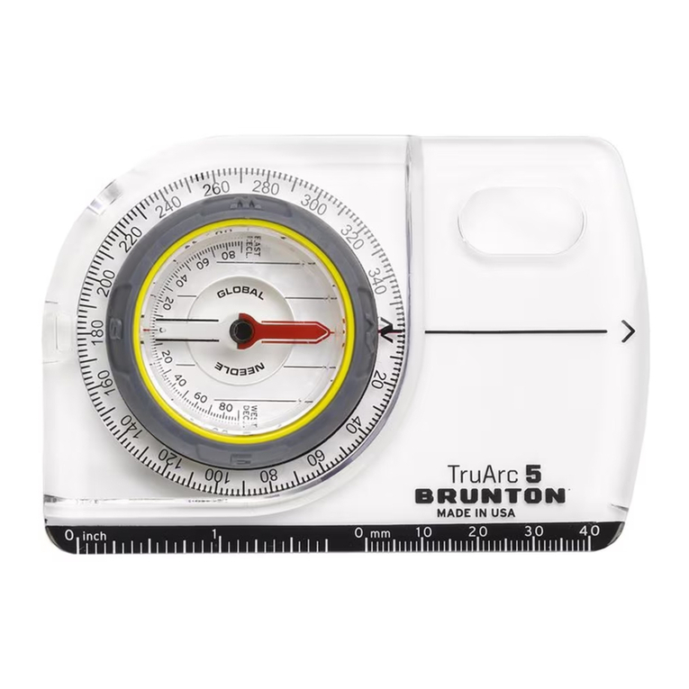
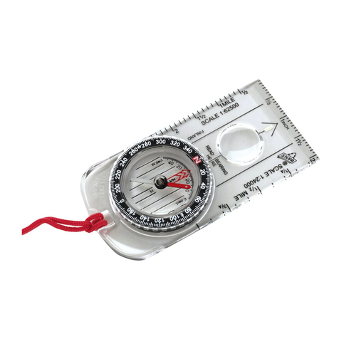
Brunton ECLIPSE 8099 User manual
Other Brunton Compass manuals
Brunton
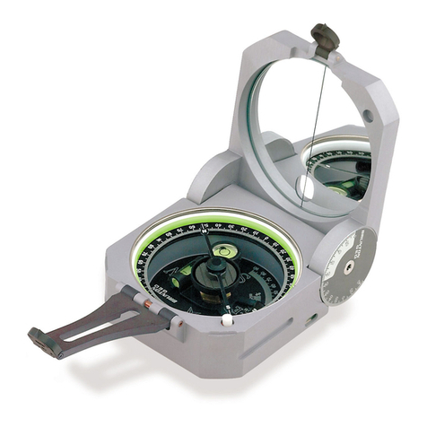
Brunton Transit User manual
Brunton
Brunton 9020G Quick setup guide

Brunton
Brunton 9075 User manual

Brunton
Brunton 7DNL User manual

Brunton
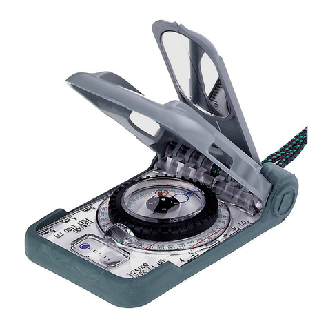
Brunton 16B Braille User manual
Brunton
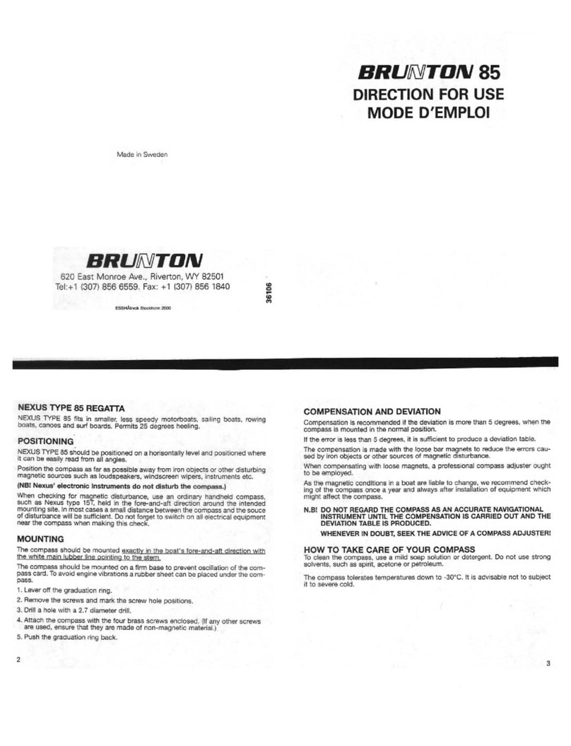
Brunton 85R Manual

Brunton
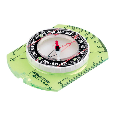
Brunton Classic Compass User manual
Brunton
Brunton Nomad 2004 User manual
Brunton
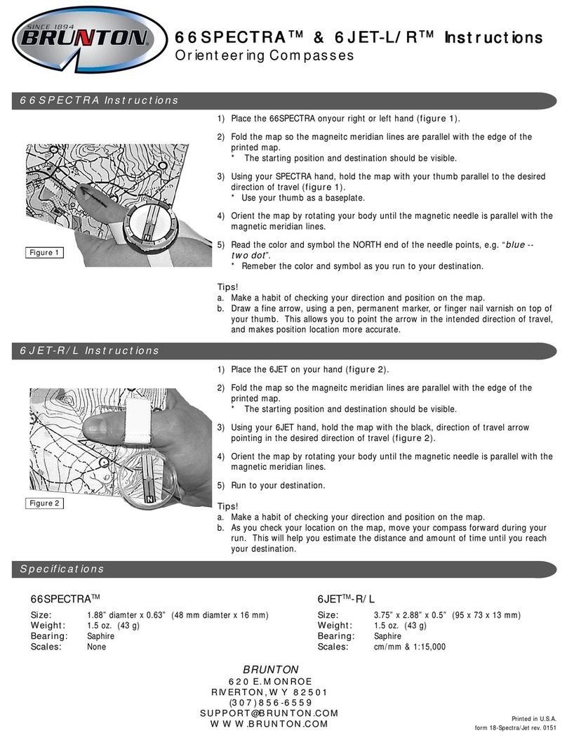
Brunton 66Spectra User manual
Brunton
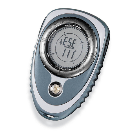
Brunton Outback User manual
Brunton
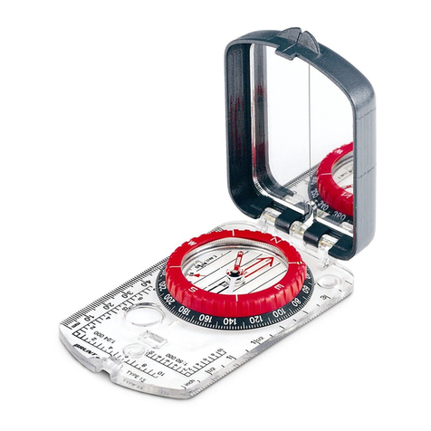
Brunton Nomad V2 Pro User manual
Brunton
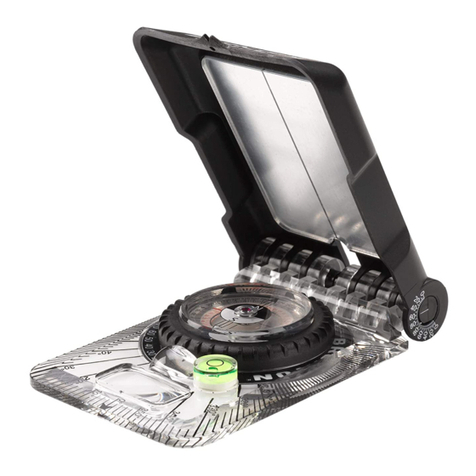
Brunton 15TDCL User manual
Brunton
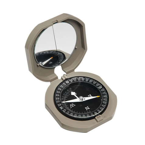
Brunton GEO LITE TRANSIT F-5030 User manual
Brunton
Brunton Cadet User manual

Brunton
Brunton OmniSlope User manual

Brunton
Brunton 54lu User manual

Brunton
Brunton Classic User manual
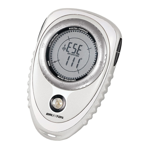
Brunton
Brunton Nomad V2 User manual
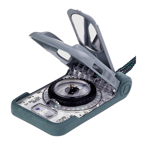
Brunton
Brunton ECLIPSE 8099 User manual

Brunton
Brunton 9020 User manual
Popular Compass manuals by other brands

TECHTRAIL
TECHTRAIL Trailhead user guide

Furuno
Furuno Sc 50 Operator's manual
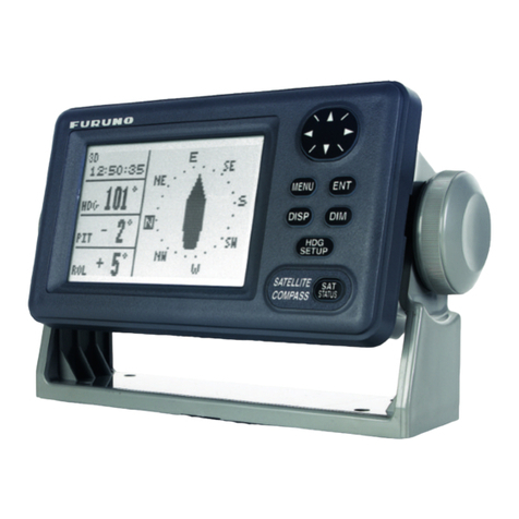
Furuno
Furuno SC-110 Operator's manual
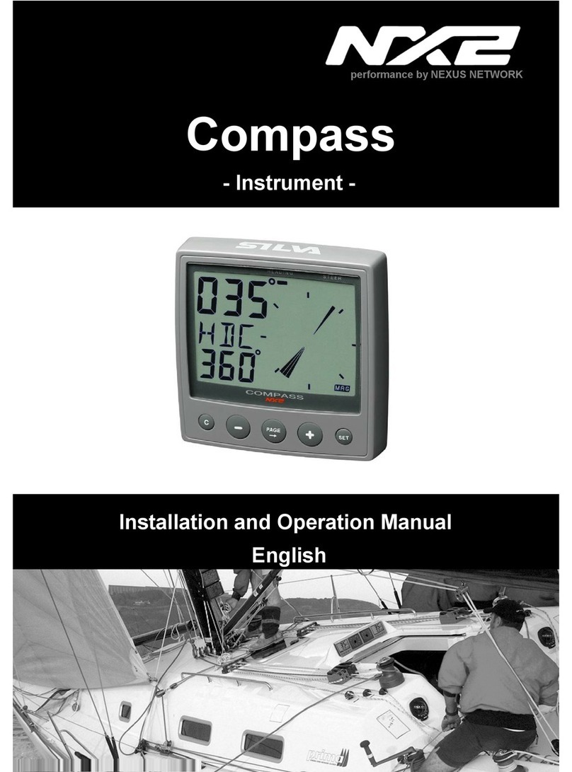
Nexus
Nexus NX2 Compass Installation and operation manual
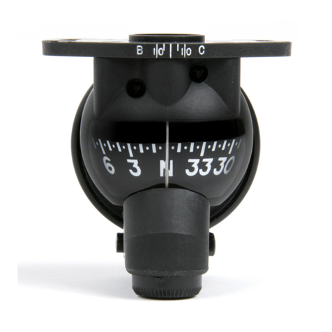
SIRS Navigation
SIRS Navigation KCA0101C COMPONENT MAINTENANCE MANUAL WITH ILLUSTRATED PARTS LIST

Raymarine
Raymarine ST40 Quick reference guide


