Blease Frontline Sirius Use and care manual

1Repair and Calibration Maintenance Manual
Frontline Sirius®
Blease
Frontline Sirius
Anaesthetic Machines
Repair and Calibration Manual
Part Number: 136SM001
Issue 2 / October 2005
0120
MODIFICATIONS LABEL
ECN 4678 ECN 2
ECN 3
ECN 4
ECN 5
ECN 6
ECN 7ECN 8ECN 9ECN 10

2Repair and Calibration Maintenance Manual
Frontline Sirius®
Important
Read this manual before operating or servicing the machine.
Read the vaporizer manual before operating the machine.
For all users and Service Personnel, refer to the User Manual before
operating the machine.

3Repair and Calibration Maintenance Manual
Frontline Sirius®
Table of Contents
Product Improvement..................................................................................................................7
Responsibilities of the Manufacturer.......................................................................................7
Disclaimer.......................................................................................................................................7
Note to Service Personnel...........................................................................................................8
Copyright.........................................................................................................................................8
CE Marking......................................................................................................................................8
Trademarks and Acknowledgements.......................................................................................9
Symbols and Abbreviations........................................................................................................10
Hazard Notices .............................................................................................................................11
Warnings.........................................................................................................................................12
Electrostatic Sensitive Devices (ESD) Warnings and Cautions...........................................13
Cautions...........................................................................................................................................13
1. Technical Description.............................................................................................................17
1.1 Mode Descriptions for the Sirius Ventilators..............................................................................................23
1.1.1 PEEP....................................................................................................................................................................23
1.1.2 Control Panel.................................................................................................................................................23
1.1.3 Control System.............................................................................................................................................23
1.1.4 Volume Control Ventilation (CMV)...................................................................................................24
1.1.5 8500s Ventilator Fresh Gas and Compliance Compensation............................................24
1.1.6 Fresh Gas..........................................................................................................................................................24
1.1.7 Compliance.....................................................................................................................................................24
1.1.8 Pressure Control Ventilator (PCV).....................................................................................................26
1.1.9 Inspiratory Pause.........................................................................................................................................26
1.1.10 Sigh......................................................................................................................................................................26
1.1.11 Spontaneous or PSV..................................................................................................................................26
1.1.12 Pressure Support.........................................................................................................................................26
1.1.13 SIMV....................................................................................................................................................................27
1.2 Matrix of Modes, Facilities and Alarms..........................................................................................................29
1.2.1 CMV Defaults at Start up........................................................................................................................29
1.2.2 Spontaneous with Pressure Support Defaults at Start up...................................................30
1.2.3 Pressure Control Ventilation Defaults at Start up....................................................................30
1.2.4 6700 8700 8500MKII Principles of Operation............................................................................34
2. Removal / Replacement Instructions.................................................................................35
2.1 Removal of Outer Cases........................................................................................................................................37
2.2 Mechanical Hypoxic Guard Block.....................................................................................................................45
2.2.1 Introduction....................................................................................................................................................45
2.2.2 Calibration of Hypoxic Guard System.............................................................................................46
2.2.3 Calibration Procedure...............................................................................................................................46
2.3 Setting Oxygen Basal Flow....................................................................................................................................49
2.4 Nitrous Oxide and Air Flow Valve Leak Test..............................................................................................54
2.5 Removal of Flow Tubes..........................................................................................................................................55
2.6 Mechanical Hypoxic Guard Regulators, Adjustment and Output Check...................................57
2.6.1 Hypoxic Regulator Replacement.........................................................................................................59
2.7 Backbar Test..................................................................................................................................................................61
Introduction

4Repair and Calibration Maintenance Manual
Frontline Sirius®
2.7.1 Backbar Valve Test......................................................................................................................................61
2.7.2 Backbar Valve Replacement..................................................................................................................63
2.8 Common Gas Outlet (CGO) Removal / Replacement.........................................................................65
2.9 Alarm Block Removal / Replacement.............................................................................................................66
2.10 Oxygen Flush of Common Gas Outlet Safety Valve Adjustment..................................................67
2.10.1 Oxygen Flush Adjustment.......................................................................................................................68
2.11 Flow Meter Removal...............................................................................................................................................69
2.12 On/Off Switch Removal........................................................................................................................................71
2.13 Absorber Interface Manifold Assembly........................................................................................................73
2.13.1 Absorber ..........................................................................................................................................................74
2.13.2 Bellows Interface Gasket.........................................................................................................................77
2.13.3 Absorber Alignment...................................................................................................................................78
2.13.4 Standby / Run...............................................................................................................................................78
2.13.5 Absorber Docking........................................................................................................................................79
2.14 Writing Surface + Drawer Removal................................................................................................................80
2.15 Drawer Catch Removal / Replacement.......................................................................................................83
2.16 Suction Controller Removal / Replacement..............................................................................................85
2.17 Full System Test.........................................................................................................................................................87
2.17.1 Leak Test...........................................................................................................................................................87
2.17.2 On/Off Switch and Warning System Checks...............................................................................88
2.17.3 Mechanical Hypoxic Guard Test..........................................................................................................89
2.17.4 Oxygen Flush Tap Test..............................................................................................................................89
2.17.5 Auxiliary Outlet Test...................................................................................................................................89
2.17.6 Vaporizer Test................................................................................................................................................89
2.17.7 Ventilator Test................................................................................................................................................89
2.18 Inspiratory Block Assembly.................................................................................................................................91
3. Ventilator Calibration Details.............................................................................................97
3.1 BleaseTerm.....................................................................................................................................................................99
3.1.1 Controls..........................................................................................................................................................100
3.1.2 Flow Control Calibration.......................................................................................................................103
3.1.3 Sensor Calibration....................................................................................................................................108
3.1.4 Zero Offset Correction...........................................................................................................................108
3.1.5 Pressure Sensor Gain..............................................................................................................................113
3.1.6 Delivered Volume Calibration............................................................................................................115
3.1.7 Fresh Gas Flow Sensor Gain...............................................................................................................117
3.1.8 Hardware Pressure Overload Backup...........................................................................................118
3.1.9 6700 Additional Steps............................................................................................................................119
3.1.10 On Screen Calibration.............................................................................................................................120
3.1.11 Fresh Gas Calibration..............................................................................................................................120
3.1.12 Monitored Inspired and Expired Volume (vte + vti).............................................................120
3.1.13 6700 Only......................................................................................................................................................121
3.1.14 Calibration Value Limits.........................................................................................................................122
3.1.15 SPC Configuration for 6700 Oxygen..............................................................................................123
3.1.16 SPC Configuration for 8700 Oxygen..............................................................................................123
4. Diagrams................................................................................................................................125

5Repair and Calibration Maintenance Manual
Frontline Sirius®
List of Figures
Figure 1 Frontline Sirius 3000..............................................................................................18
Figure 2 Frontline Sirius 2000 + 1000................................................................................20
Figure 3 Inspired gas Flow Diagram...................................................................................31
Figure 3a Absorber Pneumatic Schematic...........................................................................32
Figure 4 Sirius 3000 Pneumatic Schematic.......................................................................33
Figure 5 Removal of Top Surface........................................................................................37
Figure 6 Removal of Front Moulding..................................................................................40
Figure 7 Front of Machine.....................................................................................................40
Figure 8 Close up of front of Machine...............................................................................41
Figure 9 Rear of Machine......................................................................................................42
Figure 10 Location of Rear Screws........................................................................................43
Figure 11 Part Rear Panel Removed.....................................................................................43
Figure 12 Complete Rear Panel Removed...........................................................................44
Figure 13 Assembled Hypoxic Guard Unit...........................................................................50
Figure 14 Exploded View of Hypoxic Guard Components...............................................51
Figure 15 Flow Block showing tube filters and tube lower inserts...............................52
Figure 16 View of Assembled Hypoxic Guard from Below..............................................53
Figure 17 Flow Tube Removal................................................................................................55
Figure 18 Test Points................................................................................................................57
Figure 19 Regulator Adjustment............................................................................................58
Figure 20 Regulator Nut...........................................................................................................59
Figure 21 Regulator Flow Direction......................................................................................60
Figure 22 Back bar....................................................................................................................63
Figure 23 Back bar Valve.........................................................................................................64
Figure 24 CGO Block.................................................................................................................65
Figure 25 Alarm Block Removal.............................................................................................66
Figure 26 CGO Adjustment......................................................................................................67
Figure 27 Valve and Adjuster Disc Removed......................................................................68
Figure 28 Flow Meter Removal...............................................................................................69
Figure 29 On/Off Switch Removal ........................................................................................71
Figure 30 Absorber Interface Manifold Assembly.............................................................73
Figure 31 Absorber....................................................................................................................74
Figure 32 Bellows Interface Gasket.......................................................................................77
Figure 33 P-Clip..........................................................................................................................78
Figure 34 Writing Surface + Drawer Removal....................................................................80
Figure 35 Drawer Catch Removal / Replacement..............................................................83
Figure 36 Suction Controller Removal / Replacement.....................................................85
Figure 37 Suction Controller in Position..............................................................................86
Figure 38 Ventilator Case Top................................................................................................91
Figure 39 Inside Ventilator......................................................................................................92
Figure 40 Blease Term Start Screen......................................................................................100
Figure 41 BleaseTerm Sensor Calibration...........................................................................101
Figure 42 BleaseTerm Ventilator Options............................................................................101
Figure 43 BleaseTerm Defaults/Save Options....................................................................102
Figure 44 Flow Control Calibration.......................................................................................103
Figure 45 Sensor Calibration..................................................................................................108

6Repair and Calibration Maintenance Manual
Frontline Sirius®
Figure 46 Pressure Sensor Gain............................................................................................113
Figure 47 Delivered Volume Calibration.............................................................................115
Figure 48 Fresh Gas Flow Sensor Gain................................................................................117
Figure 49 Hardware Pressure Overload Backup...............................................................118
Figure 50 BAV Power Supply..................................................................................................126
Figure 51 BAV Controller Type 2 PWM................................................................................127
Figure 52 BAV Controller Type 2 Analogue........................................................................128
Figure 53 BAV Controller Type 2 Connect...........................................................................129
Figure 54 8700 Electrical Interconnection..........................................................................130
Figure 55 BAV Controller Type 2 CPU..................................................................................131
Figure 56 6700/8700 Pneumatic System Diagram...........................................................132
Figure 57 Blease Display Interface.......................................................................................133
Figure 58 Blease Display Interface.......................................................................................134
Figure 59 BAV Controller Type 2 Alarms.............................................................................135
Figure 60 Blease Display Interface.......................................................................................136
Figure 61 Blease Display Interface.......................................................................................137
Figure 62 Blease Display Interface.......................................................................................138
Figure 63 BAV Controller Type 2 I/O Circuits.....................................................................139
Figure 64 BAV Controller Type 2 Memory..........................................................................140

7Repair and Calibration Maintenance Manual
Frontline Sirius®
Product Improvement
Blease Medical Equipment Limited has a policy of continued product improvement and
therefore reserves the right to make changes which may affect the information contained
in the manual without giving prior notice.
Responsibilities of the Manufacturer
The manufacturer accepts responsibility for the effects on safety, reliability and performance of
the equipment only if:
• assembly operations, extensions, adjustments, modifications and repairs are
carried out by persons with written authorisation from the manufacturer;
• the equipment is used in accordance with the instructions for use;
• the electrical installation of the relevant room complies with the ‘Regulations for
the Electrical Equipment of Buildings’.
NB
If during the warranty period the equipment is serviced by an unauthorised
party, the warranty will be void.
Disclaimer
Opening of the control unit by unauthorised personnel automatically voids all warranties and
specifications. The prevention of tampering is solely the user's responsibility; the manufacturer
assumes no liability for any malfunction or failure of the ventilator if the control unit is opened.
The instructions in this manual assume that the engineer is familiar with and has
had training in the servicing and care of anaesthetic equipment and is able to use
pressure gauges, flowmeters and other laboratory equipment.
Blease accept no responsibility or liability for any patient injury or adverse
circumstances which may arise from unauthorised maintenance of Blease Frontline
Sirius Machines.

8Repair and Calibration Maintenance Manual
Frontline Sirius®
Note to Service Personnel
The Frontline Sirius®and integrated equipment must only be serviced by Qualified Service
personnel.
The contents of this manual are not binding. If any significant difference is found between the
product and this manual please contact Blease Medical Equipment Limited for further
information.
To ensure correct functioning, the equipment must be serviced at regular intervals.
Blease Medical Equipment Limited recommends that the machine should be serviced at
intervals not exceeding three months. Qualified Service Personnel and genuine spare parts
should be used for all servicing and repairs. Blease Medical Equipment Limited will not
otherwise assume responsibility for the materials used, the work performed or any possible
consequences of the same.
In communication with Blease Medical Equipment Limited, quote the model and serial number
of the equipment, with the approximate date of purchase. If the equipment is being returned
for repair, indicate the nature of the fault or the work you require to be carried out.
Contact:
Blease Medical Equipment Limited
Beech House •Chiltern Court •Asheridge Road •Chesham •Buckinghamshire HP5 2PX •
England
Tel: +44 (0)1494 784422
Fax: +44 (0)1494 791497
e-mail (enquiries): sales@blease.com
e-mail (technical): [email protected]
www.blease.com
Copyright
©2005, Blease Medical Equipment Limited. E & OE.
All rights reserved. The information contained in this publication may not be used for any other
purpose than that for which it was originally supplied.
This publication may not be reproduced in part or in whole without the written consent of
Blease Medical Equipment Limited.
CE Marking
The product is labelled with the CE mark. 0120

9Repair and Calibration Maintenance Manual
Frontline Sirius®
Trademarks and Acknowledgements
The following symbols and acknowledgments may appear in Blease product manuals:
is the trademark of Abbott Laboratories.
Da-LitesTM is a trademark of Blease Medical Equipment Limited UK.
Datum® is a registered trademark of Blease Medical Equipment Limited UK.
Dowty is a trademark of Dowty Seals Limited.
Draeger is a trademark of Draegerwerk AG Germany.
Dzus is a trademark of Dzus Fasteners Limited.
Fomblin® is a registered trademark of Rocol Limited.
Frontline Sirius 1000®is a registered trademark of Blease Medical Equipment Limited.
Frontline Sirius 2000® is a registered trademark of Blease Medical Equipment Limited.
Frontline Sirius 3000® is a registered trademark of Blease Medical Equipment Limited.
Legrand® is registered trademark of Legrand Electric Limited.
Loctite® is a registered trademark of Loctite Corporation USA.
Megger is a trademark of AVO Megger Instruments Ltd.
Plug-in® is a registered trademark of Draegerwerk DAG Germany.
Quik-Fil® is a trademark of Abbott Laboratories.
Rigel is a trademark of Seaward Electronics Ltd.
Scotchbrite® is a registered trademark of 3M.
SELECTATEC® is a registered trademark of Ohmeda/BOC UK Ltd.
Snoop® is a registered trademark of the Nupro® Company Ohio USA.
Trak Wheel®is a registered trademark of Blease Medical Equipment Ltd.

10 Repair and Calibration Maintenance Manual
Frontline Sirius®
Symbols and Abbreviations
bpm BPM
cmHO
CPAP
PEEP
2
l/m lpm
ml
O
psi
psig
l
Breaths per minute
Gauge pressure expressed in centimetres of water
Continuous positive airway pressure
Positive end expiratory pressure
IEC symbol to consult the instructions for use
Power off
Power on
Dangerous voltage
Litres per minute
Millilitres
Oxygen
Pounds per square inch
Pounds per square inch gauge
Litres
IEC symbol for alternating current
Confers approval under theEuropean Medical Device Directive
End of Case
2
A ratio of inspiratory to expiratory timeI:E Ratio
IEC symbol denoting type of equipment (B)
WARNING: There is danger of personal injury to the
user or patient
Further relevant or helpful information
E of C
This symbol indicates that the waste of electrical and electronic
equipment must not be disposed as unsorted municipal waste
and must be collected separately. Please contact an authorized
representative of the manufacturer for information concerning
the decommissioning of your equipment.

11Repair and Calibration Maintenance Manual
Frontline Sirius®
Hazard Notices
This handbook contains important hazard information. You must read this hazard
information before using the Frontline Sirius®.
Warning Notices
Warning notices denote a potential hazard to the health and safety of users and/or
patients. These notices clearly state the nature of the respective hazard and the
means by which it can be avoided.
Warning notices appear in full in the preliminary pages and are repeated at their
points of application in the manual.
Caution Notices
Cautionary notices denote a potential hazard to the physical integrity of
equipment/software but NOT a danger to personnel. These notices clearly state
the nature of the hazard and the means by which it can be avoided.
Cautionary notices appear in full in the preliminary pages and are repeated at their
points of application in the manual.
Relevant or helpful Information

12 Repair and Calibration Maintenance Manual
Frontline Sirius®
Warnings
The following statements are made to comply with the requirements of IEC 60601-1.
1. This equipment must only be connected to gas pipeline supply lines that are fitted with
pressure relief valves that limit the supply pressure to less than 7 bar.
2. The functioning of this machine may be adversely affected by the operation of equipment
such as high frequency surgical (diathermy) equipment, defibrillators or shortwave therapy
equipment in the vicinity. Increasing the distance from such equipment will minimise any
possible interference.
3. Prior to connecting the machine to a patient carry out the pre-use check to verify correct
alarm operation. To verify the O2 alarm, set the flowmeters to give a concentration of 50%
oxygen. Using the controls on the oxygen monitor panel, set the low oxygen level to 60%
and verify the oxygen low alarm operates. Set the high oxygen alarm level to 40% and
verify that the oxygen high alarm operates.
4. The oxygen flow can only be reduced to zero by turning the ON/OFF switch to the OFF
position. Excessive force on the oxygen control knob may damage the hypoxic guard.
5. To avoid explosion hazards, flammable anaesthetic agents such as ether and cyclopropane
must not be used in these machines. Only anaesthetic agents which comply with the
requirements on non-flammable anaesthetic agents in IEC 60601-2-13 ‘Specification for
Anaesthetic Machines’, are suitable for use in these machines.
6. As these machines are not suitable for use with flammable anaesthetic agents such as ether
and cyclopropane the use of antistatic breathing tubes and face masks is not necessary.
The use of antistatic or electrically conductive breathing tubes when utilising high frequency
surgery equipment may cause burns and is therefore not recommended in any application
that involves such apparatus.
7. The equipment must be periodically checked and maintained to ensure proper operation.
8. Performance of the equipment may be affected at temperatures below 10oC (50oF) and
above 40oC (104oF).
9. The performance of the anaesthetic machines and vaporizers may be degraded if the two
are mismatched. Refer to the vaporizer manufacturer’s instruction manual before use.
10. If the integrated oxygen analyser is not fitted, an oxygen analyser complying with ISO 7767
shall be used when the anaesthetic machine is in use.
11. The units use semiconductor devices which are susceptible to damage by overloading,
reversed polarity, electrostatic discharge and excessive heat or radiation. Avoid hazards
such as reversal of batteries, prolonged soldering, strong RF fields or other forms of
radiation, use of insulation testers or accidentally applied short circuits. Even the leakage
current from an unearthed soldering iron may cause trouble.

13Repair and Calibration Maintenance Manual
Frontline Sirius®
Electrostatic Sensitive Devices (ESD)
Warnings and Cautions
All ESD must be stored in approved conductive packaging, tubes, shipping bags, foam or tote
bins.
All persons handling ESD must be properly grounded via a 1MW resistive grounded wrist strap.
Cover all ESD bench tops with grounded conductive mats and connect all work surfaces and
equipment to earth ground.
Transport all assemblies containing ESD in a conductive bag or container.
DO NOT use cellophane adhesive tape to wrap DIP (dual in-line package) tubes together.
DO NOT handle ESD by their pins or mix them with other routine electronic parts.
Never place ESD on ungrounded surfaces or leave them unattended in an open area.
Avoid cellophane wrappers, synthetic (non-conductive) carpeting, warm or cool air blasts,
Styrofoam coffee cups, etc when working with ESD.
Use only properly designed heat lamps, heat chambers and/or ‘antistatic’ quick-chill sprays
during troubleshooting or stress testing procedures.
NB
In particular electronic assemblies in the Frontline Sirius®range of machines are easily damaged
by ESD and require special handling.
Cautions
Anaesthetic Machines
Do not leave gas cylinder valves open if the pipeline supply is in use and the system master
switch is turned ON. Pressures from both supplies may become equal and, if simultaneously
used, cylinder supplies could be depleted, leaving an insufficient reserve supply in case of
pipeline failure.
The hypoxic guard control system only ensures that oxygen-nitrous mixtures will have a
minimum oxygen concentration. HYPOXIC MIXTURES MAY BE DELIVERED IF GASES OTHER
THAN OXYGEN, NITROUS OXIDE OR AIR ARE USED, OR WHEN OPERATING AT LOW
OXYGEN FLOW RATES. When using carbon dioxide, as an additional gas, make sure the
proportions of all gases are carefully adjusted in accordance with accepted clinical practice. Gas
mixtures within the breathing system must be monitored when using these gases.

14 Repair and Calibration Maintenance Manual
Frontline Sirius®
Leaking gases and vapours (downstream of the flow control valves and Oxygen Flush valve)
may deprive the patient of metabolic gases and anaesthetic agent may pollute the atmosphere.
Tests that detect leaks must be performed frequently. If detected, leakage must be reduced to
an acceptable level.
Do not use the anaesthesia system if the hypoxic guard control system does not operate within
permitted ranges. Using an incorrectly operating control system may result in incorrect gas
mixtures and injury to the patient.
When occluding the breathing system for test purposes, do not use any object small enough to
slip completely into the system. Objects in the breathing system can interrupt or disrupt the
delivery of breathing system gases, possibly resulting in injury to the patient. Before using the
breathing system on a patient, always check the breathing system components for foreign
objects.
Do not place materials weighing more than 50kg on the bottom shelf, or more than 25kg on
the upper monitor shelf. Overloading may cause damage to the shelves or cause instability.
Secure any equipment placed on the shelves.
To avoid stripping threads, do not use tools on the yoke gate T screws. Use only one cylinder
gasket per yoke. Using more than one gasket could cause cylinder gas leakage.
Ventilator
The volume sensor must be correctly installed at either the distal location in the patient system’s
expiratory limb or the proximal end of the Y connector. If the sensor is installed incorrectly,
volume data will be inaccurate and associated alarms, including the low minute volume alarm
will not function properly.
Position the volume sensor’s cable with care. If the cable is pinched or cut, the ventilator’s
volume monitoring may not function correctly.
Do not connect the ventilator or absorber exhaust directly to a vacuum source. The vacuum
may remove required gases from the breathing system. (Only applies to Frontline Sirius 1000®
and 2000®).
Ventilator inoperative messages indicate that a problem exists in the ventilator. Do not attempt
to use the ventilator while a ventilator message is displayed.
Do not attempt to use the ventilator if the alarm mute button will not silence alarms.
WARNING: If an alarm condition cannot be resolved, do not continue to use the
system.
Sterilise the bellows assembly periodically to minimise the risk of cross infecting patients. Use a
sterilization schedule that complies with your institution’s infection control and risk
management policy. Only use Blease approved sterilization methods.
If any foreign materials or liquids are trapped in the driving gas circuit, or the pop off valve or
the bellows base they could impair the valve’s operation. Do not use the bellows assembly if

15Repair and Calibration Maintenance Manual
Frontline Sirius®
you suspect that materials are trapped. Have the assembly repaired by trained service
personnel.
Perform the Pre-Use Check procedures after cleaning and sterilizing the bellows.
Always perform the Pre-Use Check procedures for volume sensing functions after cleaning or
replacing the volume sensor.
Vaporizer
Do not use any vaporizer that is visibly misaligned on the manifold or that, when it is locked,
can be lifted off the manifold. Incorrect mounting may result in incorrect delivery of gases.
A vaporizer is calibrated and labelled for one agent only. Do not fill with anything other than
the designated agent.
If a vaporizer is filled with the wrong agent, draining will not eliminate the agent, because the
wick will have absorbed some of the agent. The wick must be thoroughly cleaned and dried by
trained service personnel.
The vaporizers must be completely upright for the sight glass to properly indicate agent levels.
Never oil or grease any oxygen equipment unless the lubricant used is made and approvedfor
this type of service. In general, oils and greases oxidise readily, and -in the presence of oxygen -
will burn violently. Fomblin is the recommended oxygen service lubricant (stock number
ST7014).
After performing any maintenance or repair procedure, always verify proper operation of the
system before returning to use.
Use cleaning solution sparingly. Do not saturate system components. Excessive solution can
damage internal devices.
Following ethylene oxide sterilization, quarantine the equipment in a well ventilated area to
allow dissipation of absorbed ethylene oxide gas. In some cases, aeration periods of seven days
or more may be required. Aeration time can be decreased when special aeration devices are
used. Follow the sterilizer manufacturer’s recommendations for aeration periods required.

16 Repair and Calibration Maintenance Manual
Frontline Sirius®
Notes

17Repair and Calibration Maintenance Manual
Frontline Sirius®
1. Technical Description
1. Technical Description
18 Repair and Calibration Maintenance Manual
Frontline Sirius®
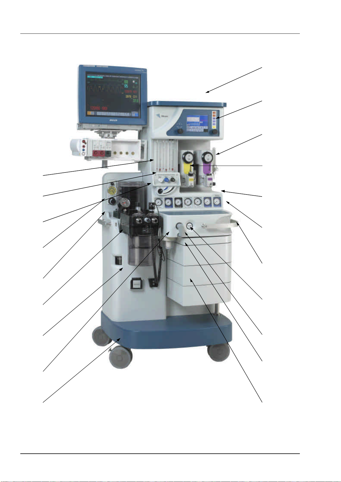
Figure 1 Frontline Sirius®3000
1. Technical Description
L
A
B
C
D
E
F
G
H
I
J
K
M
N
O
P
Q
R
S
T
1. Technical Description

19Repair and Calibration Maintenance Manual
Frontline Sirius®
Key to Figure 1
AMonitor shelf
BVentilator
CIndependent O2Flowmeter (only on the 3000 model)
DVaporizer
ECylinder/Pipeline Gauges
FPneumatic Unit -(behind gauge panel)
GHandle
HOxygen Flush
ICommon Gas Outlet
JWriting Table
KDrawer
LFrame
MSuction Receiver Jar
NAnaesthetic Gas Scavenging System (AGSS)
OAbsorber
PBellows
QSuction Controller
RMain On/Off or Off, N2O/Air Interlock Switch
SFlow Control Valves with Hypoxic Guard
TFlowblock Assembly
1. Technical Description
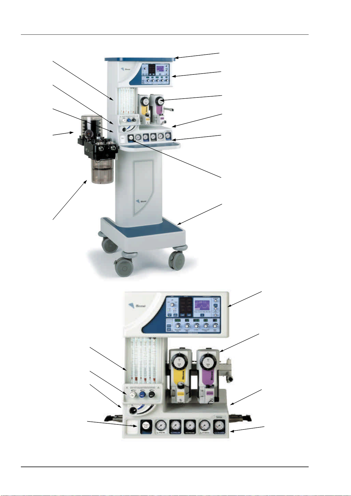
20 Repair and Calibration Maintenance Manual
Frontline Sirius®
B
F
C
D
E
G
A
H
I
J
J
L
Fig 2 Sirius 2000 &
Sirius 1000
M
N
O
P
T
S
R
Q
1. Technical Description
Table of contents
Other Blease Medical Equipment manuals


