Penlon A200SP User manual

A200SP Absorber User Manual
ANAESTHESIA SOLUTIONS


A200SP Absorber User Manual
IMPORTANT
Servcng and Repars
In order to ensure the full operatonal lfe of ths devce,
servcng by a Penlon-traned engneer should be undertaken
perodcally
The absorber must be servced to the schedule detaled n
secton 71
Detals of these operatons are gven n the A200SP Absorber
servce manual, avalable only for Penlon-traned engneers
For any enqury regardng the servcng or repar of ths devce,
contact the nearest accredted Penlon agent
or communcate drectly wth
UK and ROW, except USA
Techncal Support
Penlon Lmted
Abngdon Scence Park
Abngdon, OX14 3NB, UK
Tel +44 (0) 1235 547060
Fax +44 (0) 1235 547061
E-mal techsupportpenloncom
USA
Penlon Inc
11515 K-Tel Drve
Mnnetonka
MN 55434
USA
Toll Free 800-328-6216
Tel 952-933-3940
Fax 952-933-3375
E-mal customerservcepenloncom
Always gve as much of the followng nformaton as possble
1 Type of equpment
2 Product name
3 Seral number (refer to the devce ID label)
4 Approxmate date of purchase
5 Apparent fault

A200SP Absorber User Manual
Foreword
Ths manual has been produced to provde authorsed
personnel wth nformaton on the functon, routne,
performance and mantenance checks applcable to the
A200SP Absorber
Informaton contaned n ths manual s correct at the date of
publcaton The polcy of the manufacturer s one of contnued
mprovement to ther products Because of ths polcy the
manufacturer reserves the rght to make any changes whch
may affect nstructons n ths manual, wthout gvng pror
notce
Personnel must make themselves famlar wth the contents
of ths manual and the absorber functon before usng the
apparatus
IMPORTANE OF PATIENT MONITORIN
WARNIN
Anaesthesa systems have the capablty to delver mxtures
of gases and vapours to the patent whch could cause nury
or death unless controlled by a qualfed anaesthetst
There can be consderable varaton n the effect of
anaesthetc drugs on ndvdual patents so that the settng
and observaton of control levels on the anaesthesa system
does not n tself ensure total patent safety
Anaesthesa system montors and patent montors are very
desrable ads for the anaesthetst but are not true clncal
montors as the condton of the patent s also dependent
on hs respraton and the functonng of hs cardo-vascular
system
IT IS ESSENTIAL THAT THESE ELEMENTS ARE MONITORED
FREQUENTLY AND REULARLY AND THAT ANY
OBSERVATIONS ARE IVEN PREEDENE OVER MAHINE
ONTROL PARAMETERS IN JUDIN THE STATE OF A
LINIAL PROEDURE
Before usng any montorng system or devce, the user must
check that t conforms to the relevant standards

A200SP Absorber User Manual
User Responsibility ........................................................................................... 1
1. Warnings and Cautions ..................................................................................... 2
2. Purpose.................................................................................................. 4
3. Description................................................................................................ 5
3.1 Canister .................................................................................................6
3.1.1 Mounting.............................................................................................. 6
3.1.2 Gas Flow Direction......................................................................................6
3.1.3 Release/Lock System ...................................................................................6
3.1.4 Absorbent Capacity .....................................................................................7
3.2 Inspiratory and Expiratory Non-return Valves (NRV) .............................................................7
3.3 Bag/Ventilator Switch ......................................................................................7
3.4 Adjustable Pressure Limiting (APL) Valve ......................................................................8
3.5 AGSS Outlet and Fresh Gas Inlet and Hose.....................................................................8
3.6 Manometer ..............................................................................................8
3.7 Heater Unit (option)........................................................................................ 9
3.7.1 Absorber Gas Path Heater ...............................................................................9
3.7.2 Spirometer Sensor Heater ................................................................................9
3.8 Bypass System............................................................................................9
3.9 End Tidal Carbon Dioxide Monitoring .........................................................................9
3.10 Interface to Ventilator .................................................................................... 10
3.10.1 Interface functions..................................................................................... 10
3.10.2 Bag/Ventilator Switch .................................................................................. 10
3.11 Gas Flow...............................................................................................11
4. Specification ............................................................................................. 12
4.1 General Dimensions ......................................................................................12
4.2 Resistance of Breathing System. . . . . . . . . . . . . . . . . . . . . . . . . . . . . . . . . . . . . . . . . . . . . . . . . . . . . . . . . . . . . . . . . . . . . . . . . . . . . 12
4.2.1 Resistance Measurement Parameters..................................................................... 12
4.2.2 Expiratory Resistance .................................................................................. 12
4.2.3 Inspiratory Resistance .................................................................................. 12
4.3 Internal Compressible Volume.............................................................................. 13
4.4 System Leakage Rate .....................................................................................13
4.5 Canister Capacity and Resistance ...........................................................................13
4.5.1 Canister Capacity ...................................................................................... 13
4.5.2 Canister Resistance .................................................................................... 13
4.6 Non-return Valves ........................................................................................14
4.7 Heater (option)........................................................................................... 14
4.8 Device Classification and Labelling ..........................................................................14
4.9 Environmental ...........................................................................................15
5. Installation and Operation.................................................................................. 16
5.1 Install the Absorber.......................................................................................16
5.2 Anaesthesia System Connection ............................................................................16
5.2.1 Breathing System ..................................................................................... 18
5.2.2 Fresh Gas Supply ...................................................................................... 18
5.2.3 Anaesthetic Gas Scavenging (AGS)........................................................................ 18
5.2.4 Oxygen Monitor. . . . . . . . . . . . . . . . . . . . . . . . . . . . . . . . . . . . . . . . . . . . . . . . . . . . . . . . . . . . . . . . . . . . . . . . . . . . . . . . . . . . . . . . 18
5.2.5 Pressure Monitor ..................................................................................... 18
5.2.6 Bag/Ventilator Switch and Spirometer .................................................................... 19
Contents

A200SP Absorber v User Manual
5.3 Changing CO Absorbent...................................................................................19
5.3.1 Cleaning ............................................................................................. 19
5.3.2 Refilling with absorbent................................................................................. 20
5.3.3 Refitting the canister ................................................................................... 20
5.4 Manometer..............................................................................................20
5.5 Heater (option)........................................................................................... 21
6. Pre-use Checks ........................................................................................ 22
6.1 Operators pre-use checklist................................................................................22
6.2 Leak Test ...............................................................................................23
63 Adustable Pressure Lmtng (APL) Valve Test and Pressure Relief Test............................................ 23
6.4 Inspiratory and Expiratory Non-return Valve Test .............................................................. 24
6.5 Bag/Ventilator switch test..................................................................................24
6.6 Leak Test - Absorber Canister Detached ..................................................................... 25
7. Maintenance ............................................................................................. 26
7.1 Service Schedule ......................................................................................... 26
7.2 Canister and Seals. . . . . . . . . . . . . . . . . . . . . . . . . . . . . . . . . . . . . . . . . . . . . . . . . . . . . . . . . . . . . . . . . . . . . . . . . . . . . . . . . . . . . . . . 26
7.3 Condensate Drainage .....................................................................................27
7.4 Manometer .............................................................................................28
75 Adustable Pressure Lmtng (APL) Valve .................................................................... 28
8. Sterilisation .............................................................................................. 29
8.1 Sterilisation Policy........................................................................................29
8.2 Bacterial Filters..........................................................................................29
8.3 Patient Circuit Components ................................................................................29
8.4 Absorber Assembly - Procedure Before Sterilisation ...........................................................30
8.4.1 Absorber Canister ..................................................................................... 30
8.4.2 Manometer, Oxygen Sensor, APL Valve .................................................................... 30
8.4.3 Electrical Interface, Cables, Tubing ....................................................................... 31
8.4.4 Bellows Assembly - Removal and Cleaning................................................................. 31
8.4.5 Dismantling and Cleaning the Absorber before Sterilisation ................................................... 32
8.5 Sterilisation and Disinfectant Treatment Table ................................................................33
8.5.1 Absorber ............................................................................................. 33
8.5.2 Ventilator Bellows ..................................................................................... 33
8.6 Absorber Assembly Reassembly after Cleaning and Sterilisation .................................................34
8.6.1 Ventilator Bellows ..................................................................................... 34
8.6.2 Absorber ............................................................................................. 34
9. APPENDIX ............................................................................................... 35
Appendix 1 References....................................................................................... 35
Appendix 2 Disposal at end of useful life - risk assessment.........................................................35
Appendix 3 Optional extras and approved accessories .............................................................35
Appendix 4 Labelling .........................................................................................36
Appendix 5 Electromagnetic compatibility (EMC)..................................................................37

A200SP Absorber 1 User Manual
User Responsibility
Ths devce has been bult to conform wth the specfcaton and
operatng procedures stated n ths manual and/or accompanyng
labels and notces when checked, assembled, operated,
mantaned and servced n accordance wth these nstructons
To ensure the safety of ths devce t must be checked and
servced to at least the mnmum standards lad out n ths
manual A defectve, or suspected defectve, product must not
under any crcumstances be used
The user must accept responsblty for any malfuncton whch
results from non-complance wth the servcng requrements
detaled n ths manual
Addtonally, the user must accept responsblty for any
malfuncton whch may result from msuse of any knd, or
non-complance wth other requrements detaled n ths
manual
Worn, broken, dstorted, contamnated or mssng components
must be replaced mmedately Should such a repar become
necessary t s recommended that a request for servce advce be
made to Penlon Lmted or the nearest Penlon Servce entre
Ths devce and any of ts consttuent parts must be repared
only n accordance wth wrtten nstructons ssued by Penlon
Lmted and must not be altered or modfed n any way
wthout the wrtten approval of Penlon Lmted
The user of ths equpment shall have the sole responsblty
for any malfuncton whch results from mproper use,
mantenance, repar, damage or alteraton by anyone other
than Penlon Lmted or ts apponted agents
USA and anadan Federal Law restrcts the sale and use of
ths devce to, or on the order or, a lcensed practtoner
Statements n ths manual preceded by the followng words
are of specal sgnfcance-
WARNIN
ndcates a possblty of nury to yourself or others
AUTION
ndcates a possblty of damage to the apparatus or other
property
NOTE
ndcates ponts of partcular nterest for more effcent and
convenent operaton
The reader must take partcular notce of the warnngs,
cautons and notes provded throughout ths manual

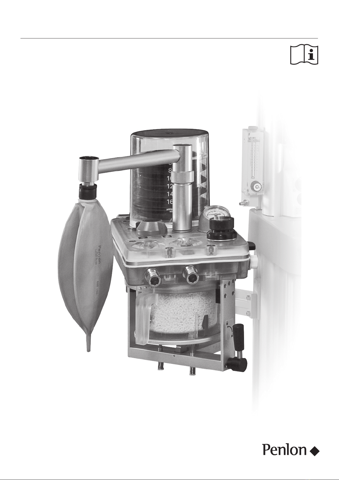
A200SP Absorber 2 User Manual
1. Warnings and Cautions
The followng WARNINS and AUTIONS must be read and
understood before usng ths Anaesthetc Apparatus
WARNINS
1 Personnel must make themselves famlar wth the
contents of ths manual and the functon of the A200SP
Absorber before use
2 Trchloroethylene must not be used n assocaton wth
soda lme
3 Ths unt s restrcted to use wth non-flammable
anaesthetc agents only
4 The A200SP Absorber must only be used when securely
mounted n an uprght poston
a) The nspratory and expratory non-return valves
(NRV) are gravty operated See secton 32
b) Spllage of absorbent may contamnate the breathng
system See secton 51
5 To avod the rsk of electrc shock, ths equpment must
only be connected to a mans supply wth a protectve
earth
6 To solate the machne from the mans power supply,
dsconnect the mans cable from the mans power outlet
Always use an easly accessble mans power outlet
7 Ths devce must not be altered or modfed n any way
wthout the wrtten approval of Penlon Lmted
Before usng the absorber
8 Breathng system connecton Do not use a patent
Y-pece contanng non-return valves Usage wth the
Absorber s hazardous, because two sets of non-return
valves may easly be connected n opposton, by error
See secton 52
9 Breathng hoses and bags used wth the absorber must
comply to BS EN ISO 5367 (Hoses) and BS EN ISO 5362
(Breathng Bags) respectvely
10 Do not connect a vacuum systems must not drectly to
the adustable pressure lmtng (APL) valve outlet A
recevng system wth postve and negatve pressure
control functons must be nterposed Systems must
comply wth EN ISO 8835 Part 2 or BS EN ISO 80601-2-
13 See secton 523
11 The APL valve s out of crcut when the system s n
‘Ventlator’ mode The ventlator must be equpped wth a
pressure relef valve
12 Underfllng of the canster can lead to neffcent O
absorpton Overfllng may result n poor sealng of
canster due to cakng of granules and abrason of the
canster and seal See secton 532
13 Anhydrous soda lme s known to react wth some
anaesthetc agents Do not contnue to use an absorbent
f t has been allowed to dry out (or f you suspect t has
dred out) Always replace dred-out absorbent wth a
fresh supply of soda lme
14 Do not use the absorber wthout ensurng that t passes
all pre-use checks See secton 6After servcng and
cleanng procedures, verfy postve acton of the bag/
ventlator selector swtch before the unt s used
clncally
heck that at all tmes that the swtch s free to move
from one end of ts travel to the other
Usng the absorber
15 ondensaton, whch may collect n the bottom of the
absorber canster s caustc and care must be taken not
to spll t on the skn when dranng See secton 73
16 Knkng of the fresh gas hose s a known cause of
anaesthetc accdent The use of an unsutable hose
assembly can contrbute to ths stuaton
See secton 35
17 Any system utlsng the A200SP absorber must be ftted
wth
a) An oxygen montor complyng wth ISO/IE 80601-2-
55
b) A carbon doxde montor complyng wth ISO/IE
80601-2-55
c) A mnute volume montor
d) A breathng system ntegrty alarm
18 Refttng the canster
The canster seals at the top face Mantan the poston
of the rm of the canster over the outer lp of the seal as
you rotate the lever ant-clockwse to the vertcal, locked-
on poston
Falure to lock the canster n the fully closed poston,
may cause a system leak and/or a reducton n O
absorpton
19 Heater unt (f ftted)
Exteror panels must not be removed by unauthorsed
personnel, and the unt must not be operated wth such
panels mssng
There s a possble electrc shock hazard
20 Portable RF communcatons equpment (ncludng
perpherals such as antenna cables and external
antennas) should be used no closer than 30 cm (12
nches) to any part of ths devce, ncludng cables
specfed by the manufacturer Otherwse, degradaton of
the performance of ths equpment could result
21 You must only use non-conductve breathng system
hoses Breathng hoses must not have electrcally
conductve propertes
22 Ths machne s not sutable for use n oxygen-rch
envronment
23 Do not touch any electrcal devce connector at the same
tme as the patent

A200SP Absorber 3 User Manual
Warnings and Cautions
User mantenance
24 User mantenance s restrcted to cleanng the outsde
surfaces of the absorber - see secton 7
Other procedures detaled n ths manual must be carred
out by traned techncans
Servce and repar operatons must only be carred out by
an engneer traned by the manufacturer The warranty
for ths product s vod f the product s not mantaned n
accordance wth the servce schedule detaled n secton
71, and the procedures publshed n the Servce Manual
for ths product
AUTIONS
1 Do not sterlse (autoclave) the manometer
2 Do not allow any lqud to run nto the electrcal nterface
unt at the rear of the absorber Do not autoclave
3 Do not allow any lqud to run nto the heater unt (f
ftted) Do not autoclave
4 Autoclavng the absorber canster
Dscard the absorbent and dran the condensate from the
canster, then reft the canster to the absorber assembly,
before autoclavng (see secton 84)
5 Autoclave temperatures maxmum temperatures are
lsted n secton 815
6 If the absorber has to be lfted or carred by hand, always
support the weght of the unt under the base
Do not lft the absorber by grppng any of the
components attached to the top of the absorber - the
manometer, adustable pressure lmtng (APL) valve,
breathng crcut connectors, etc
7 Do not use any ventlator wth the A200SP absorber that
does not comply wth EN ISO 8835 Part 2 or BS EN ISO
80601-2-13

A200SP Absorber 4 User Manual
2. Purpose
Intended use
The A200SP Absorber s ntended for use by a professonal
operator n a professonal healthcare envronment, and must
be contnually attended when n use
The absorber s desgned to be mounted on an anaesthetc
workstaton The absorber transmts gas mxture to and from
a patent Soda lme housed n a canster mounted on the
absorber, s used to absorb exhaled O
Intended patent populaton
Ths product s ntended to be used for a patent populaton
from neonatal to adult when used n conuncton wth a Penlon
approved ventlator
Intended part of the body or type of tssue appled to or
nteracted wth
No drect nteracton wth any part of the human body The
absorber s used to transmt ventlated gas to and from a
patent whlst absorbng O n the patent expred gas
ontrandcatons
The standard A200SP Absorber s not sutable for use n an
MRI envronment ontact Penlon Lmted for detals of the
A200SP MRI Absorber

A200SP Absorber 5 User Manual
3. Description
1 Adustable pressure lmtng valve (APL valve)
2 Inspratory non-return valve (NRV)
3 Inspratory hose connector
4 Bag/ventlator swtch
5 Reservor bag connector
6 anster
7
5
8
6
11
1
2
3
12
9
4
10
7 Ventlator bellows housng
8 Electrcal nterface unt
9 Expratory hose connector
10 Expratory non-return valve (NRV)
11 Manometer
12 anster release lever

A200SP Absorber 6 User Manual
Description
3.1 Canister
3.1.1 Mounting
The absorber must only be used when securely mounted n an
uprght poston – spllage of absorbent may contamnate the
breathng system – see WARNIN, n secton 51
3.1.2 Gas Flow Direction
as flows through the canster (1) from top to bottom
See also, secton 311
NOTE
The bag/ventlator connecton s between the absorber
and the patent Bag squeezng or the use of mechancal
ventlaton does not result n the transport of dust toward the
patent, but tends to drve dust back nto the absorber
3.1.3 Release/Lock System
The canster release/lock mechansm s operated by a lever (2)
at the base of the canster assembly The lever s shown n the
vertcal, locked on poston n the upper llustraton
WARNIN
1 If the absorbent s to be changed durng clncal use,
adequate fresh gas flow must be mantaned to prevent
excessve buld up of O2
2 ondensaton, whch may collect n the bottom of the
absorber canster, s caustc Avod skn contact when
dranng
Release
1 Swvel the front of the absorber assembly away from the
sde of the anaesthetc machne
2 Turn the lever (2) clockwse to the unlocked poston (3) to
release the canster
Reft and Lock
3 Reft the canster - lft upwards (4) and poston the rm of
the canster over the outer lp of the seal (5)
4 Hold the canster n place, check that there s no lateral
movement Turn the lever (2) ant-clockwse to the vertcal
poston to lock the canster n place
WARNIN
The canster seals at the top face Mantan the poston of
the rm of the canster over the outer lp of the seal (5) as
you rotate the lever ant-clockwse to the vertcal, locked-on
poston
Falure to lock the canster n the fully closed poston, may
cause a system leak and/or a reducton n O absorpton
5 Leak test the absorber - see secton 62
12
3
1
2
4
2
5

A200SP Absorber 7 User Manual
Description
3.1.4 Absorbent Capacity
The canster nner contaner (1) holds 13 kg (equvalent to
1500 ml) of loose absorbent
DO NOT OVERFILL - see secton 53
Alternatvely, a standard sze pre-pack unt can be used n the
canster (2) n place of the nner contaner (see secton 53)
Remove the nner contaner from the canster f a pre-pack
unt s to be used
Refll Durng Use (see secton 53)
WARNIN
If the absorbent s to be changed durng clncal use,
adequate fresh gas flow must be mantaned to prevent
excessve buld up of O
3.2 Inspiratory and Expiratory Non-return
Valves (NRV)
The valves are postoned on the top of the manfold block (1)
and control the drecton of the gas flow through the system
Each valve conssts of a dsc located over a valve seat The
dscs operate by gravty and are retaned by gudes to prevent
lateral movement
The valves are vsble through the top cover (2) and the
operaton of each valve can be vsually checked as the patent
breathes n and out
IT IS IMPORTANT THAT THE ABSORBER IS MOUNTED
UPRIHT SO THAT THE VALVE DISS MOVE IN A TRULY
VERTIAL PLANE, WITH THE VALVE SEATS HORIZONTAL
3.3 Bag/Ventilator Switch
The swtch (1) can be set to bag or ventlator postons See
Appendx 3 for swtch poston labellng
Ventlator mode
In ‘Ventlator’ mode the reservor bag s closed off from the
breathng system and the ventlator connecton port at the rear
of the manfold block, s n crcut
WARNIN
The adustable pressure lmtng (APL) valve (2) s out
of crcut when the system s n ‘Ventlator’ mode The
ventlator must be equpped wth a pressure relef valve
Bag mode
The breathng bag acts as an addtonal over-pressure
protecton devce, preventng pressure exceedng 60 cmHO
WARNIN
If no ventlator s connected to the absorber, care must be
taken to ensure that the bag/ventlator swtch s kept n the
‘Bag’ poston, to avod gross loss of gas from the breathng
system and to mantan the reservor bag n the system
1
2
1
2
2
1

A200SP Absorber 8 User Manual
Description
3.4 Adjustable Pressure Limiting (APL) Valve
The APL valve (1) s a sprng loaded plastc float wth a rubber
seal, provdng breathng system pressure control, and excess
pressure relef
The sprng pressure can be vared by rotatng the control
knob on top of the valve In the fully counterclockwse poston
the mnmum pressure s 10 cmHO at 6 L/mn Ths can be
ncreased by clockwse rotaton to 60 cmHO
As shown n the graph, further clockwse rotaton causes a
rapd ncrease n openng pressure so that n the fully closed
poston, the valve functons as a 60 cmHO excess pressure
relef valve
WARNIN
The APL valve (1) s out of crcut when the system s n
‘Ventlator’ mode The ventlator must be equpped wth a
pressure relef valve
3.5 AGSS Outlet and Fresh Gas Inlet and
Hose
ASS (anaesthetc gas scavengng system) connector
Taper connector (1) at rear of absorber assembly
Fresh as Inlet and Hose
The fresh gas nlet (2) s at the rear of the absorber
The absorber s suppled wth a fresh gas hose assembly wth
an attached end fttng Do not use any other type of hose
WARNIN
Knkng of the fresh gas hose s a known cause of
anaesthetc accdent The use of an unsutable hose
assembly can contrbute to ths stuaton
3.6 Manometer
The use of a manometer s strongly recommended at all tmes
The manometer (1) s located on the top of the manfold block
Manometer scale -10 to +100 cmHO
Manometer accuracy ±5% (wthn range +10 to 80 cmHO)
AUTION
Remove the manometer before autoclavng the absorber
manfold block - see secton 85
1
Open losed
lockwse rotaton
60
Pressure
(cmHO)
1
2
1

A200SP Absorber 9 User Manual
Description
3.7 Heater Unit (option)
NOTE
Interrupton of the heater unt mans power supply wll result n
the heater unt not functonng
When the Mans power plug s removed from the heater unt power
socket (4)
• Power to the heater unt (2) s nterrupted
• The heater unt (2) s solated from the mans supply
The heater unt (2) and the auxlary heater element (5) each
have a sngle power ndcator lamp The power ndcator lamp s
llumnated when mans power s appled to the assembly
3.7.1 Absorber Gas Path Heater
The heater elements are mounted wthn the support blocks (1)
mounted at each sde of the top of the heater control unt (2) The
elements heat the base of the absorber and lmt the buld up of
mosture n the gas paths
The heater operates automatcally, When the heater s powered,
usng the socket (4), a power ndcator lamp (3) on the sde of the
unt s llumnated
AUTION
Do not autoclave the heater unt or heater elements
3.7.2 Spirometer Sensor Heater
The sprometer sensors are mounted nsde the electrcal nterface
unt (5) and each sensor s heated by an ndvdual heater element
to lmt the buld up of mosture and mantan sensor performance
The heater elements operate automatcally, a power ndcator
lamp (6) s llumnated, when the cable (7) s connected to the
socket (8) on the heater control unt
AUTION
Do not autoclave the electrcal nterface unt
3.8 Bypass System
The absorber reverts to bypass mode when the canster release
lever s turned clockwse to the unlocked poston (1)
Expratory gas cycles to the patent, wthout passng through the
absorbent
It s strongly recommended that a capnometer s used to prevent
the rsk of hypercapna
3.9 End Tidal Carbon Dioxide Monitoring
The use of end tdal carbon doxde (EtO) montorng s strongly
recommended
onnecton of a sutable analyser must be made between the
patent’s arway and the patent connecton Y-pece
Read the nstructons provded by the manufacturer of the
analyser
53 12
8
6
7 2 5
4
1

A200SP Absorber 10 User Manual
Description
3.10 Interface to Ventilator
3.10.1 Interface functions
The absorber s desgned to nterface wth the anaesthesa
system ventlator control unt (1)
Note also that the ventlator bellows unt (2) s bult nto the
absorber
A cable lnks the multfuncton connector (3) on the nterface
unt at the rear of the absorber to the connector (4) on the
ventlator control unt
Ths provdes an nterface between the ventlator and (a) the
sprometer flow sensors, and (b) a sensor that detects the
poston of the bag/ventlator swtch (5) - see secton 3102
below
3.10.2 Bag/Ventilator Switch
1 The absorber s ftted wth ftted wth a sensor that detects
the poston of the absorber bag/ventlator control swtch
(5)
A mechancal lnk actuates the sensor and the sgnal
cablng s routed nternally to the multfuncton connector
(3)
2 Operaton of the bag/ventlator control wll trgger
automatc Mode swtchng on the ventlator, as follows
a) Ventlator n Volume mode or Pressure mode
Swtchng the absorber bag/ventlator control from
ventlator to bag
The ventlator wll change from Volume Mode, or
Pressure Mode, to Spontaneous Mode
b) Ventlator n Spontaneous Mode
Swtchng the absorber bag/ventlator control from
Bag to Ventlator
NOTE
The mode swtchng operaton s dependant on the
orgnal selecton process used by the clncan to
reach Spontaneous Mode
If the ventlator was prevously n Volume Mode,
or Pressure Mode, and Spontaneous Mode was
automatcally selected by the operaton of the
bag/ventlator control (from ventlator to bag, as
descrbed above)
- the ventlator wll now revert to that prevous
mode
If the ventlator was n Standby Mode, and
Spontaneous Mode was selected on-screen
- the ventlator wll revert to Volume Mode
NOTE
a) operaton of the absorber bag/ventlator control wll
have no effect on the ventlator unless the above
condtons are met
b) Ths functon can be enabled/dsabled through the
ventlator on-screen menu (see Appendx, n the
ventlator user manual)
1
4
2
5
3

A200SP Absorber 11 User Manual
Description
3.11 Gas Flow
Inspratory as Path
A Patent as from bellows
B Through the bag/ventlator swtch
Down to absorbent canster
D Through the absorbent
E Fresh gas flow from anaesthetc machne
F Into the nspratory non-return valve
Through nspratory connector to patent breathng crcut
as Flow Schematc
NOTE
The schematc represents the gas path wth the absorber ‘ON’
(e the absorbent canster n the ‘locked-on’ poston, see
secton 313)
1 Ventlator bellows
2 Bag/ventlator swtch
3 Absorbent canster
4 Fresh gas flow from anaesthetc machne
5 Inspratory non-return valve
6 Adustable pressure lmtng valve (APL) valve
7 Breathng bag
8 Patent
9 Expratory non-return valve
10 Manometer
11 Pressure montor sample lne
12 Ventlator drve gas
13 Oxygen montor sensor
14 Sprometer flow sensors
E
G
D
F
C
B
A
1
12
7
3
6
14
2
9
10
11
8
5
13
14
4

A200SP Absorber 12 User Manual
4. Specification
4.1 General Dimensions
All values are approxmate
Overall heght 380 mm
Wdth 186 mm
Depth 240 mm
Weght (empty) 57 kg
Mountng system Polemount assembly
4.2 Resistance of Breathing System
4.2.1 Resistance Measurement Parameters
Resstances lsted n secton 422 and secton 423 are
measured wth
a) An absorber ftted wth 1060 mm (42 nch) breathng
hoses complyng wth BS EN ISO 5367, and a Safelock
Y-pece
b) Absorber only
NOTE
1 The canster must be flled to the correct level wth fresh
absorbent (follow the nstructons n secton 53)
2 A bacteral flter must be used n the patent breathng
system to protect the oxygen sensor
Use an approprate flter that does not rase the resstance
values of the whole system to above 06 kPa (6 cmHO)
3 The adustable pressure lmtng (APL) valve must be fully
open
4.2.2 Expiratory Resistance
Tested, as detaled n secton 421, wth a flow of 6 L/mn of
ar through the fresh gas nlet and an nduced flow of 60 L/mn
through the breathng system
a) Expratory resstance Less than 06 kPa (6 cmHO)
b) Expratory resstance Less than 05 kPa (5 cmHO)
4.2.3 Inspiratory Resistance
Tested, as detaled n secton 421, wth a flow of 6 L/mn of
ar through the fresh gas nlet and an nduced flow of 60 L/mn
through the breathng system
a) Inspratory resstance Less than 06 kPa (6 cmHO)
b) Inspratory resstance Less than 045 kPa (45 cmHO)

A200SP Absorber 13 User Manual
4.3 Internal Compressible Volume
Note that the reservor bag s not ftted and the bag mount
blocked when measurements are taken
These fgures are measured wth
1 An absorber ftted wth 1060 mm (42 nch) breathng
hoses complyng wth BS EN ISO 5367, and a Safelock
Y-pece Volume requred to rase the system pressure to 3
kPa (30 cmHO) = 180 ml
2 Absorber only
Volume requred to rase the system pressure to 3 kPa (30
cmHO) = 170 ml
For other dsposable breathng hoses, the suppler of the hose
wll provde compressble volume data
4.4 System Leakage Rate
Seal the patent connecton port and the fully close the
adustable pressure lmtng (APL) valve
These fgures are measured wth
1 An absorber ftted wth 1060 mm (42 nch) breathng hoses
complyng wth BS EN ISO 5367, and a Safelock Y-pece
Absorber ‘ON’, canster n locked-on poston
Leakage rate less than 50 ml/mn at 3 kPa (30 cmHO)
2 Absorber only
Absorber ‘OFF’, canster detached
Leakage rate less than 50 ml/mn at 3 kPa (30 cmHO)
4.5 Canister Capacity and Resistance
4.5.1 Canister Capacity
When flled to the correct level (see secton 53), the canster
nner contaner holds 13 kg (287 lb) of absorbent (1500 ml)
Recommended absorbent
Soda lme, wth a colour ndcator, 4-8 mesh
Use bulk packed (loose) or pre-packs
NOTE
1 The absorber canster s not electrcally conductve
2 leanng and sterlsaton detals are gven n secton 8,
Sterlsaton
4.5.2 Canister Resistance
The resstance of a freshly flled canster s less than 02 kPa
(2cmHO) at 60 L/mn
Specification

A200SP Absorber 14 User Manual
4.6 Non-return Valves
Pressure drop across the nspratory and expratory non-
return valves at an ar flow of 60 L/mn 01 kPa (1 cmHO)
NOTE
Flow characterstcs are dentcal for valves n a dry or wet
condton
A ‘wet’ valve s defned as a valve n a flow of humdfed gas,
such that mosture s vsble on the surface of the valve
4.7 Mode of Operation
Mode of Operaton ontnuous
4.8 Heater (option)
Voltage 100 - 240 VA
urrent 16 A at 100 VA
09 A at 240 VA
Frequency 50/60 Hz
Fuse T2AH 250 V
4.9 Device Classification and Labelling
The Absorber and ts consttuent parts are classfed as
follows
Type B Appled Part
Degree of protecton aganst electrc shock
Ths symbol denotes
Type B equpment
lass 1 lassfcaton
Type of protecton aganst electrc shock lass 1
IPX0 Ingress protecton
lassfcaton accordng to the degree of protecton aganst
ngress of water IPX0 (not protected)
Sterlzaton
A lst of absorber components that may be sterlzed s gven n
secton 8
Oxygen compatblty
The A200SP absorber s not sutable for use n an oxygen rch
envronment
lassfcaton Labellng
Refer to Appendx 4
002 004 006 008 010
60
50
40
30
20
10
Flow
(L/mn)
Pressure
(kPa)
Specification
Table of contents
Other Penlon Medical Equipment manuals
Popular Medical Equipment manuals by other brands

Huntleigh
Huntleigh AKRON 3 SECTION DRAINAGE Service manual

INQUA
INQUA 504G0007 Instructions for use

PremiumLift
PremiumLift AirCare Max-5 user manual

GE
GE Datex-Ohmeda S/5 Series Technical reference manual

Gainsborough
Gainsborough KENT 1800 Series 2 Information manual

Neurosoft
Neurosoft Poly-Spectrum-8/V Technical manual