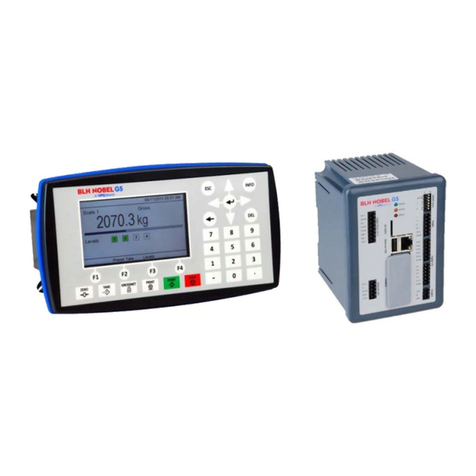
BLH NOBEL G5 User manual

G5 Weighing Instrument
Program version 1.3.X
Fieldbus Option Manual
PM and RM types


CONTENTS
1. Introduction ...................................1-1
General................................................1-1
Module installation ..............................1-1
Ordering information ...........................1-2
2. Modules ........................................2-1
Profibus-DP Module............................2-1
DeviceNet Module...............................2-3
ControlNet Module ..............................2-5
EtherNet/IP Module.............................2-6
3. Set-up ...........................................3-1
General................................................3-1
Fieldbus related parameters ...............3-1
4. Output Data...................................4-1
Commands..........................................4-2
5. Input Data......................................5-3
Number format....................................5-9
Examples.............................................5-9
6. Fieldbus interface..........................6-1
EtherNet/IP..........................................6-2
Profibus DP-V1 ...................................6-3
DeviceNet............................................6-3
ControlNet...........................................6-3
7. Maintenance..................................7-1
General................................................7-1

Technical Manual
PRECAUTIONS
READ this manual BEFORE operating or servicing this instrument. FOLLOW these
instructions carefully. SAVE this manual for future reference.
INTENDED USE
The G5 Instrument family are measuring and control devices intended for industrial
systems. Its basic function is to convert the signals from transducers to useful
information. Transducer excitation is included as well as parameter controlled signal
processing, indication of output levels, error supervision and operation of optional
external equipment. The instrument supports several types of communication
interfaces.
INSTRUMENT INSULATION AND GROUNDING
The cable connector for mains power supply should include protective grounding for
safety. The cable for 24VDC power supply (screw terminal connector) should include a
ground connected to terminal GND.
The input groups of the instrument are insulated from each other by functional
insulation. The mains connection of AC-powered instruments has reinforced insulation
according to IEC 61010. Terminals intended for connection of cable shields are
connected to the protective ground of the mains or GND terminal of 24VDC input but
must not be considered as protective grounding. Shield connection of load cell input is
not connected to mains protective ground or 24VDC GND terminal.
Change description
Revision 0: First release of this document.
!
WARNING
Only permit qualified personnel to install and service this instrument.
Exercise care when making checks, tests and adjustments that must be
made with power on. Failing to observe these precautions can result in
bodily harm.
DO NOT allow untrained personnel to operate, clean, inspect, maintain,
service, or tamper with this instrument.

G5 Weighing Instrument
1-1
1. Introduction
General
The G5 Instruments are high performance single-channel weight indicators (PM model,
panel mounted) or weight transmitters (RM model, DIN rail mounted) intended for
industrial systems. This manual describes the functionality of the optional Fieldbus
interface of the G5 Instrument. The instrument supports the following busses:
ProfibusDP, DeviceNet, ControlNet and EtherNet/IP. The optional fieldbus module is
mounted in the Fieldbus slot.
l fieldbus settings are done with setup parameters in the instrument. No settings are
done on the module itself.
Module installation
Make sure the instrument power supply is off or disconnected. Remove the plastic
cover from the fieldbus slot. Insert the adaptor very carefully and make absolutely
sure that the adaptor slides correctly into the guidesin the connector on the PCB.
Tighten the two fastening screws at the adaptor front and check that the two securing
hooks locks into the PCB.
Module type Connector Baud rate Address Bus Supply
Voltage
Profibus-DP
Profibus
9-pin, female
D-sub (DB9F)
9.6 kbps –
12 Mbps or
Auto set by
parameter
1 – 125,
set by parameter
DeviceNet
5 pin male
connector. 125, 250,
500 kbps or
Auto set by
parameter.
0 – 63,
set by parameter According to
DeviceNet (Node)
specification:
nominal 24 VDC,
range 11 – 25
VDC.
ControlNet
BNC. Fixed 5
Mbit/s. 1 – 99, set by
parameter
EtherNet/IP
Dual RJ45
(Only port 1
,P1) is
supported
Selectable Static
or DHCP. If static
choosen IP-
address, Net
Mask and Default
Gateway are set
by parameters.

Technical Manual
1-2
Ordering information
If an (optional) fieldbus module is needed it must be ordered together with the
instrument. Ordering numbers are shown below. If multiple instruments and/or fieldbus
modules are purchased in the same order it must be clearly specified which module
should be mounted in which instrument.
Optional ProfibusDP fieldbus module
P/N: 110559 (ordering number).
Optional DeviceNet fieldbus module
P/N: 110560 (ordering number).
Optional ControlNet fieldbus module
P/N: 110838 (ordering number).
Optional EtherNet/IP fieldbus module
P/N: 110859 (ordering number).
Example showing product information
and installed option(s).

G5 Weighing Instrument
2-1
2. Modules
Profibus-DP Module
Profibus module front view
(1) Operation mode LED.
(2) Status LED.
(3) Profibus connector.
Operation mode LED
State Indication
Off Not online / No power
Green On-line, data exchange
Flashing Green On-line, clear
Flashing Red (1 flash) Parameterization error
Flashing Red (2 flashes) Profibus configuration error
Status LED
State Indication
Off No power or not initialised
Green Initialised
Flashing Green Initialised, diagnostic event(s) present
Red Exception error
OP ST
PROFIBUS DP-V1
(1) (2)
(3)

Technical Manual
2-2
Profibus connector (DB9F)
Pin Signal Description
1 - -
2 - -
3 B line Positive RxD/TxD, RS485 level
4 RTS Request to send
5 GND Bus Ground (isolated)
6 + 5V Bus Output +5V termination power (isolated)
7 - -
8 A line Negative RxD/TxD, RS485 level
9 - -
Housing Cable shield Functional ground internally connected to the
module protective ground via cable shield
filters according to the Profibus standard.
For connection of the adaptor to the Profibus master, use a Profibus standard cable
and connector according to the diagram below.
8. A-Line
3. B-Line
Shield
For reliable fieldbus function, line termination must be arranged in both ends of the
transmission line. For a G5 instrument, at the end of the cable, a connector with line
termination should be used. For all other G5 Instruments, connection without line
termination should be used.
For configuration of the adaptor, a GSD file (VISH0F83.GSD) is available and should
be installed in the master.
Select the 8 words output module + 2 x 16 words input modules + one 8 words input
module. This will give 16 bytes of output data and 80 bytes of input data. The PLC set-
up should match this exactly including the order of the input modules.

G5 Weighing Instrument
2-3
DeviceNet Module
DeviceNet module front view
(1) Network Status LED.
(2) Module Status LED.
(3) DeviceNet connector.
Network Status LED
State Indication
Off Not online / No power
Green On-line, one or more connections are established
Flashing Green (1 Hz) On-line, no connections established
Red Critical link failure
Flashing Red (1 Hz) One or more connections time out
Alternating Red/Green Self-test
Status LED
State Indication
Off No power
Green Operating in normal condition
Flashing Green (1 Hz) Missing or incomplete configuration
Red Unrecoverable fault(s)
Flashing Red (1 Hz) Recoverable fault(s)
Alternating Red/Green Self-test
NS MS
DeviceNet
(1) (2)
(3)
(Pin 1)

Technical Manual
2-4
DeviceNet connector
Pin Signal Description
1 V- Negative bus supply voltage
2 CAN L CAN low bus line
3 Shield Cable shield, functional ground.
4 CAN H CAN high bus line
5 V+ Positive bus supply voltage
For connection of the adaptor to the DeviceNet master, use a standard cable for
DeviceNet or similar shielded cable with twisted pairs and a connector according to the
diagram below. The bus supply voltage shall be 11 – 25 VDC.
2. CAN L
4. CAN H
1. V-
5. V+
3. Shield
For reliable fieldbus function, line termination must be arranged in both ends of the
transmission line. For a G5 Instrument placed at the end of the line, terminate line by
placing a 121-ohm resistor between CAN L (pin 2) and CAN H (pin 4).
For configuration of the adaptor an EDS file is supplied with the instrument that should
be installed in the master. Note that the EDS file is a generic type supplied by the
module manufacturer. The file doesn’t contain any reference to the G5 Instrument or to
BLH Nobel.

G5 Weighing Instrument
2-5
ControlNet Module
ControlNet module front view
(1) Network Status LED A.
(2) Module Status LED.
(3) Network Status LED B.
(4) ControlNet connector A.
(5) ControlNet connector B.
Network Status LED A/B
LED State Indication
LED A and B Off Not online / No power
Flashing Red (1 Hz) Incorrect node configuration, duplicate MAC ID
etc.
Alternating Red/Green Self-test of bus controller
Red Fatal event or faulty unit
LED A or B Off Channel is disabled
Alternating Red/Green Invalid link configuration
Flashing Green (1 Hz) Temporary errors (node will self-correct) or
node is not configured to go online
Green Normal operation
Flashing Red (1 Hz) Media fault or no other nodes on the network
Status LED
State Indication
Off No power
Green Operating in normal condition, controlled by a Scanner in
run state
Flashing Green (1 Hz) The module has not been configuration or Scanner in idle
state
Red Unrecoverable fault(s), EXCEPTION, fatal event
Flashing Red (1 Hz) Recoverable fault(s), MAC ID has been changed after
initialization etc.
ControlNet connectors
These connectors provide ControlNet connectivity. If redundancy is wanted both
connectors should be used. Otherwise either connector can be used.
A B
ControlNet
B
(1) (2) (3)
(4) (5)

Technical Manual
2-6
EtherNet/IP Module
ControlNet module front view
(1) Network Status LED.
(2) Module Status LED.
(3) Link/Activity Port 1.
(4) Link/Activity Port 2.
Network Status LED
LED State Indication
Off No power or no IP address
Green Online, one or more connections established (CIP class 1 or 3)
Green, flashing Online, no connections established
Red Duplicate IP address, fatal error
Red, flashing One or more connections timed out (CIP class 1 or 3)
Module Status LED
State Indication
Off No power
Green Controlled by a Scanner in run state
Flashing Green (1 Hz) Not configured or Scanner in idle state
Red Major fault (EXCEPTION state, fatal error etc.)
Flashing Red (1 Hz) Recoverable fault(s)
Link/Activity LED 3/4
State Indication
Off No link, no activity
Green Link (100 Mbit/s) established
Green, flickering Activity (100 Mbit/s)
Yellow Link (10 Mbit/s) established
Yellow, flickering Activity (10 Mbit/s)
NS MS
EtherNet/IP
(1) (2)
(3) (4)
P1 P2

G5 Weighing Instrument
3-1
3. Set-up
General
All operating functions in the G5 Instrument are controlled by parameters. The
parameter values are permanently stored in the instrument and will not be lost when
the unit is switched off. At delivery the parameters are factory-set to default values,
giving the instrument an initial standard function.
The actual setting of the parameter values can be read and edited during normal
measuring operation in sub menu ‘Parameter Set-up’. Editing of parameter values can
be performed using the color display and keys on the front panel of the instrument or
by using a Web Browser on a PC connected on the same network as the instrument.
After editing hardware parameters the instrument will be restarted.
In the instrument there are two levels of security locks provided to protect from
unauthorized access to instrument functions and editing of parameters and values. The
locks are opened by four-digit codes.
Fieldbus related parameters
On the following pages a survey of fieldbus related parameters is presented. The
parameters are divided in groups following the menu they belong to. For choice
parameters the available choices are given. For numerical parameters, a value range is
given.
At the end of the table, the default value is given in < >.
To the right there is a short parameter explanation and, in italic, the results for
the different alternatives.
Range/Alternatives Explanation and
<default value> result of alternatives.
Menu Hardware Configuration
Fieldbus Module
None
Profibus
DeviceNet
ControlNet
EtherNet/IP
< None >
Available Fieldbus choices.
When this set-up is changed the instrument will be restarted.
The user must confirm that the instrument is restarted. If the set-
up does not match the installed module the instrument will start
up in error state. After the mismatch is corrected and the
instrument is restarted the instrument will be operational again.
Menu Fieldbus
Note: The Fieldbus menu is not shown if parameter Fieldbus (in
Hardware Configuration menu) is set to None.
Profibus, Address
Range 1 - 125
< 126 > Profibus address setting.
Note: This parameter is only shown if parameter Fieldbus (in
Hardware Configuration menu) is set to Profibus.

Fieldbus Manual
3-2
Range/Alternatives Explanation and
<default value> result of alternatives.
DeviceNet, Address
Range 0 - 63
< 63 > DeviceNet address setting
Note: This parameter is only shown if parameter Fieldbus (in
Hardware Configuration menu) is set to DeviceNet.
ControlNet, Address
Range 1 - 99
< 99 > ControlNet address setting
Note: This parameter is only shown if parameter Fieldbus (in
Hardware Configuration menu) is set to ControlNet.
DeviceNet, Baudrate
125 kbps
250 kbps
500 kbps
Auto
< Auto >
The baud rate for a DeviceNet type of module. Must be selected
to suite the master.
125 kbps: Fixed baudrate 125 kbits/s.
250 kbps: Fixed baudrate 250 kbits/s.
500 kbps: Fixed baudrate 500 kbits/s.
Auto: Auto setting 125 – 500 kbits/s.
Note: This parameter is only shown if parameter Fieldbus (in
Hardware Configuration menu) is set to DeviceNet.
IP Address
< 192.168.99.151 > The ip address of the EtherNet/IP interface.
Note: This parameter is only shown if parameter Fieldbus (in
Hardware Configuration menu) is set to EtherNet/IP. Restart the
instrument when the ip-address has been changed.
Net Mask
< 255.255.255.0 > The net mask of the EtherNet/IP interface.
Note: This parameter is only shown if parameter Fieldbus (in
Hardware Configuration menu) is set to EtherNet/IP. Restart the
instrument when the net-mask has been changed.
Default Gateway
< 192.168.99.1 > Default gateway of the EtherNet/IP interface.
Note: This parameter is only shown if parameter Fieldbus (in
Hardware Configuration menu) is set to EtherNet/IP. Restart the
instrument when the default gateway has been changed.
Data Format
Floating Point
Integer
< Floating Point >
Sets what data format should be used. The data format choice
applies to weight and some other values. Status, error code and
other similar data which is inherently integer data is always
given as integers (no decimals)
Floating Point:IEEE 32 bit floating point format.
Integer: 32 bit integer format.
Note: This parameter is not shown if parameter Fieldbus (in
Hardware Configuration menu) is set to None.

G5 Weighing Instrument
4-1
4. Output Data
Output data mapping is shown in the table below. Output data is 8 bytes as described
in table below. Data direction is from network (PLC) to G5 Instrument.
Byte
Size
Description
0 – 1
2
Command
2 – 3
2
Parameter ID
4 – 7
4
Data to write
Command
Bytes 0 - 1: The command byte is used when writing data to the instrument and to
issue various scale related commands such as taring, zeroing etc.
Note that a new command is detected when the content of the command register is
changed. If the same command shall be issued again, the command byte must first be
set to 0 and this should be verified by reading command acknowledge. Then the
desired command may be issued.
The response to a given command is the ‘Command acknowledge’ and the
‘Command error’ bytes in the input data of the connection.
Parameter ID
Bytes 2 - 3: The selected Level (1 - 4) or Setpoint (1 - 4) to set. The data in byte 2 and
3 are ignored for any other commands than 221 and 222.
Data to write
Bytes 4 to 7: The value of the Preset tare, Level, Setpoint, Digital outputs or Analog
Output to set. Note that the format of the value should be floating point or integer
depending on the Data Format parameter. The data in bytes 4 to 7 are ignored for any
other commands than 200, 201, 220 – 222. No of decimals in an integer value is
according to the weight and flow rate set-up. Analog output (command 200) is always 3
decimals.
Example: A value with 3 decimals e.g. 7.234 should be written as 7234 to the
bytes 4 – 7.
Byte order
The byte order in multi byte values (more than one byte) is depending on the type of
fieldbus used.
Profibus DP: MSB first (Most Significant Byte first).
DeviceNet: MSB first.
ControlNet: MSB first.
EtherNet/IP: LSB first (Least Significant Byte first).

Fieldbus Manual
4-2
Commands
Cmd #
Command Name
Description
0 No action When the same command is repeated the no action
should be sent between the commands to make it
possible for the instrument to detect new commands.
1 Start operation When the instrument is in ‘Wait for start state’, this
command can be used to start up the instrument.
2 Enter Remote operation This command disables the keys on the instrument.
This means that an external computer is controlling the
instrument or the instrument is controlled using digital
inputs.
3 Exit Remote operation This command enables the keys and leaves the remote
operation.
10 Auto tare Perform a tare operation
11 Set scale to zero Zero the gross weight
12 Select gross mode Switch to gross mode (display)
13 Select net mode Switch to net mode (display)
14 Weight display Switch from flow to weight display
15 Flow rate display Switch from weight to flow display
16 Print command Initiate a print output
100 Activate setpoint 1 Activate the setpoint
101 Deactivate setpoint 1 Deactivate the setpoint
102 Activate setpoint 2
103 Deactivate setpoint 2
104 Activate setpoint 3
105 Deactivate setpoint 3
106 Activate setpoint 4
107 Deactivate setpoint 4
132 Activate setpoints 1 - 4 Activates all 4 setpoints
133 Deactivate setpoints 1 - 4 Deactivates all 4 setpoints
200 Set Analog output Remote control of analog output. Set actual current or
voltage output value.
201 Set digital outputs Remote control of digital outputs. Set or reset the 4
outputs.
220 Set Preset Tare value Set Preset Tare to desired value.
221 Set Level value Set selected Level to desired value.
222 Set Setpoint value Set selected Setpoint to desired value.
223 Clear Acc. Weight Set accumulated weight to zero.
252 Clear Program reset bit Clear the Program reset bit in the Instrument Status
register. Set at power up.

G5 Weighing Instrument
5-3
5. Input Data
Byte
Size
Description
Note
0 1 Instrument error 8
1 1 Instrument Status 8
2 1 Instrument State 8
3 1 Command acknowledge 8
4 1 Command error 8
5 1 Level status 8
6 1 Setpoint status 8
7 1 Input and Output status 8
8 – 9 2 Error code 8
10 – 11 2 Scale status 8
12 – 15 4 Gross weight 1, 2
16 – 19 4 Net weight 1, 2
20 – 23 4 Flow rate 1, 3
24 – 27 4 Input signal 1, 4
28 – 31 4 Level 1 1, 2, 3
32 – 35 4 Level 2 1, 2, 3
36 – 39 4 Level 3 1, 2, 3
40 – 43 4 Level 4 1, 2, 3
44 – 47 4 Setpoint 1 1, 2, 3
48 – 51 4 Setpoint 2 1, 2, 3
52 – 55 4 Setpoint 3 1, 2, 3
56 – 59 4 Setpoint 4 1, 2, 3
60 – 63 4 Preset tare 1, 2
64 – 67 4 Acc. weight Low 1, 5
68 – 71 4 Acc. weight High 1, 5
72 – 75 4 Analog Output 1, 6
76 – 79 4 Aux. analog input 1, 7
80 – 81 2 Clock, year 8
82 1 Clock, month 8
83 1 Clock, day 8
84 1 Clock, hour 8
85 1 Clock, minute 8
86 1 Clock, second 8
87 1 Not used 8
88 1 No of decimals in weight values 8
89 1 No of decimals in flow rate 8
90 - 105 16 Spare 9

Fieldbus Manual
5-4
Note 1: This value is in integer format if parameter Data Format is set to Integer or in float
format if parameter Data Format is set to Floating Point.
Note 2: The number of decimals used in these values depends on the resolution setting for the
scale. Actual number of decimals is shown in byte 88.
Note 3: The number of decimals used in flow rate depends on the resolution setting for the flow
rate. Actual number of decimals is shown in byte 89.
Note 4: The input signal always has 5 decimals. Unit is mV/V.
Note 5: Low part has 3 decimals.
Note 6: Analog output value always with 3 decimals.
Note 7: Analog input value always with 3 decimals.
Note 8: The value is in integer format, i.e. it does not have any decimals.
Note 9: These bytes are not used in the standard version of the G5 software. The content is
always 0.
Input data mapping is shown in the table on previous page. Input data is 106 bytes as
described in the table. Data direction is from G5 Instrument to network (PLC).
Instrument error
This register holds the overall error code for the instrument.
Normally this register should contain ‘00’ which means no error.
Instrument status
This register holds the overall status for the instrument
Bits set to 1 in this register have the following meaning:
Bit no Function Comment
0 Remote operation ‘1’ = On ‘0’ = Off
1 Program reset The bit is set each time the program starts, and it
indicates that volatile data is lost.
The bit is reset as Instrument status is read, over serial
communication (Modbus RTU) or over Ethernet (Modbus
TCP), for the first time after reset/power-up. Note that the
reply contains the set bit if it was set.
Reading Instrument Status via Fieldbus interface will not
reset this bit. To reset this bit with fieldbus interface a
specific reset command must be used.
Care must be taken if more than one interface is used to
communicate with the instrument and the Program reset
bit is to be used.
2-15 Not used

G5 Weighing Instrument
5-5
Instrument state
This register contains the state of the G5 instrument.
Code Description
00 ‘Starting up’ state.
The instrument is starting up after a reset or power on.
01 ‘Wait for start’ state.
The instrument is waiting for a start command to go in process.
02 ‘Warming up state’
The parameter ‘Warm up time’ is set to a value other than zero, and
the instrument is waiting for the warming up time to pass.
03 ‘Normal’ state.
There are no parameter errors in the system.
Note: Weight errors still indicate normal state.
04 ‘Error’ state.
An error has been detected during startup of the instrument.
05 ‘Fatal error’ state.
An error has been detected during startup of the instrument.
It’s not possible to enter any other state from here.
06 ‘Power fail’ state.
A power fail has been detected and the instrument will respond to
communication for a short moment until the power supply reserves are empty
(this is normally just a few ms). Weight values should be regarded as invalid.
Command acknowledge
This byte returns the value of the command if it could be executed. If there was an
error executing the command the value 240 (hex F0) will be returned in this byte. This
byte should be used to verify that a command has been executed.
Note that a new command is detected when the content of the command register is
changed. If the same command shall be issued again, the command byte must first be
set to 0 and this should be verified by reading command acknowledge. Then the
desired command may be issued.
Command error
This byte holds the error code when a command has been sent to the instrument.
Normally this register should contain ‘00’ which means no error. Error codes 0 to 255
are valid in this register.
Level status 1 - 4
Bits in this byte have the following meaning:
Bit no Function Comment
0 Above level 1 The weight is above Level 1.
1 Above level 2 The weight is above Level 2.
2 Above level 3 The weight is above Level 3.
3 Above level 4 The weight is above Level 4.

Fieldbus Manual
5-6
Setpoint status 1-4
Bits in this byte have the following meaning:
Bit no Function Comment
0 Setpoint 1 activated See description for setpoint function.
1 Setpoint 1 cycle done -“-
2 Setpoint 2 activated -“-
3 Setpoint 2 cycle done -“-
4 Setpoint 3 activated -“-
5 Setpoint 3 cycle done -“-
6 Setpoint 4 activated -“-
7 Setpoint 4 cycle done -“-
Status of digital inputs and outputs
Bits in this byte have the following meaning:
Bit no Function
0 Digital input 1 activated.
1 Digital input 2 activated.
2 Digital input 3 activated.
3 Digital input 4 activated.
4 Digital output 1 activated.
5 Digital output 2 activated.
6 Digital output 3 activated.
7 Digital output 4 activated.
Scale Error code
This register holds the error code for the scale. Normally this register should contain ‘000’
which means no error. Error codes 000 to 255 are valid in this register.
This manual suits for next models
2
Table of contents
Other BLH NOBEL Accessories manuals
Popular Accessories manuals by other brands
Visonic
Visonic MCT-370 SMA user manual
Heitronic
Heitronic 45017 Installation and operating instructions

Powerfix Profi
Powerfix Profi 270249 Operation and safety notes

Balluff
Balluff BES M12MG2-GNX20B-S04G-EXC user guide

HELPINSTILL
HELPINSTILL 280 quick start guide
Burkert
Burkert SE30 Ex Namur instruction manual
Dorner
Dorner SmartFlex 2200 Series Installation, maintenance & parts manual

IPVideo Corporation
IPVideo Corporation Halo Administrator's manual

AVCOM
AVCOM Galaxy Installation & operation manual

Sentronik
Sentronik SE9000A instruction manual
BERGER
BERGER K22 user manual

Philips
Philips SB7G17B Specifications
