BLH NOBEL G5-PM-S-DC-W User manual

G5 Weighing Instrument
Program version 1.4.X
Technical Manual
PM and RM types


CONTENTS
1. Introduction ...................................1-1
General................................................1-1
Maintenance........................................1-2
Safety information ...............................1-2
Technical data.....................................1-3
Ordering information ...........................1-6
2. Installation.....................................2-1
Mechanical installation........................2-1
Electrical installation............................2-3
Connection of cable shields................2-3
Front panel..........................................2-8
3. Set-up ...........................................3-1
General................................................3-1
Connecting a PC to the instrument.....3-2
Menu system.......................................3-2
Menu structure ....................................3-4
Parameters..........................................3-5
4. Calibration.....................................4-1
General................................................4-1
Common parameters ..........................4-2
Data sheet calibration .........................4-4
Table calibration..................................4-5
Deadweight calibration........................4-5
5. Operation ......................................5-1
General................................................5-1
Power-up sequence ............................5-1
Status LEDs ........................................5-1
Display at normal operation ................5-2
Security locks......................................5-3
Taring..................................................5-4
Gross/Net operation............................5-5
Zero setting .........................................5-5
Zero-tracking/Automatic zero setting ..5-6
Motion..................................................5-6
Load cell Supervision..........................5-7
Weight printing ....................................5-8
Main Menu.........................................5-10
Level supervision ..............................5-12
Setpoint function ...............................5-13
Digital inputs and outputs..................5-13
Analog output....................................5-13
Filter function.....................................5-14
Flow rate............................................5-15
6. Communication .............................6-1
General................................................6-1
Serial interface.................................... 6-1
Modbus RTU Slave............................. 6-1
Modbus TCP Slave.............................6-2
Ftp Server ...........................................6-3
Fieldbus interface................................ 6-3
Modbus protocol.................................. 6-3
7. Remote Access.............................7-1
General ............................................... 7-1
Browser requirements......................... 7-1
Using the Remote Access................... 7-2
Security............................................... 7-2
Remote Access Login and Logout...... 7-3
Remote / Local Access ....................... 7-5
8. Maintenance..................................8-1
General ............................................... 8-1
Diagnostics.......................................... 8-1
File Handling ....................................... 8-5
Create Backup .................................... 8-5
Restore Backup...................................8-5
Set Default .......................................... 8-5
Instrument Restart............................... 8-5
Program upgrade................................8-6
9. Troubleshooting.............................9-1
General ............................................... 9-1
Error codes..........................................9-1

Technical Manual
PRECAUTIONS
READ this manual BEFORE operating or servicing this instrument. FOLLOW these
instructions carefully. SAVE this manual for future reference.
INTENDED USE
The G5 Instrument family are measuring and control devices intended for industrial
systems. Its basic function is to convert the signals from transducers to useful
information. Transducer excitation is included as well as parameter controlled signal
processing, indication of output levels, error supervision and operation of optional
external equipment. The instrument supports several types of communication
interfaces.
INSTRUMENT INSULATION AND GROUNDING
The cable connector for mains power supply should include protective grounding for
safety. The cable for 24VDC power supply (screw terminal connector) should include a
ground connected to terminal GND.
The input groups of the instrument are insulated from each other by functional
insulation. The mains connection of AC-powered instruments has reinforced insulation
according to IEC 61010. Terminals intended for connection of cable shields are
connected to the protective ground of the mains or GND terminal of 24VDC input but
must not be considered as protective grounding. Shield connection of load cell input is
not connected to mains protective ground or 24VDC GND terminal.
Change description
Program version 1.4.X, document revision 0: New manual.
Compared to Program version 1.3.X the following is added:
- Fieldbus option PROFINET.
- German and French languages.
!
WARNING
Only permit qualified personnel to install and service this instrument.
Exercise care when making checks, tests and adjustments that must be
made with power on. Failing to observe these precautions can result in
bodily harm.
DO NOT allow untrained personnel to operate, clean, inspect, maintain,
service, or tamper with this instrument.

G5 Weighing Instrument
1-1
1. Introduction
General
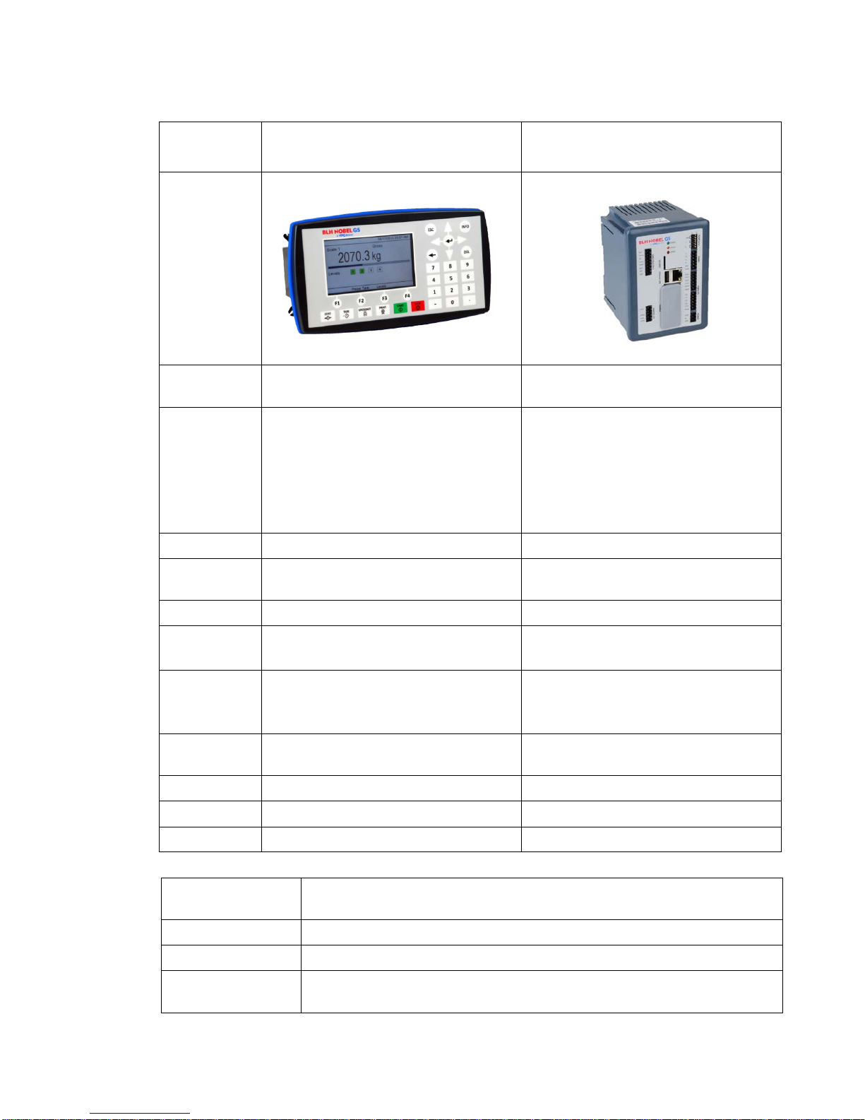
The G5 Instruments are high performance single-channel weight indicators (PM model,
panel mounted) or weight transmitters (RM model, DIN rail mounted) intended for
industrial systems.
The basic function is to convert the signals from strain gauge transducers to useful
weight information. Transducer excitation is included as well as parameter controlled
signal processing, indication of output levels, error supervision and operation of
optional external equipment.
As long as the error supervision detects no error, a signal called ‘In process’ is then
present but if an error is detected, ‘In process’ will be off and a specific error
message will be displayed. ‘In process’ can be set to control any digital output. Note
that there are weighing channel specific and instrument specific error detection.
All functions in the G5 Instrument are controlled by set-up parameters. Setting of
parameter values can be done from the PM front panel. Set-up of a RM model must be
done with a web browser in a PC that is connected to the instrument via Ethernet.
Maintenance functions can be accessed locally (PM) or remotely (PM and RM).
It is possible to load new software into the instrument using a SD-Card.
The instrument has 4 level supervising functions and 4 set-point functions.
Power supply
The G5-PM (panel mount indicator) is available as 24 VDC model or 110/230 VAC
model. The G5-RM (rail mount transmitter) is available as 24 VDC model. All input and
output signals are galvanically isolated from the power supply.
Strain gauge input
Both excitation voltage and the output signal from the transducer are measured at the
transducer to avoid influence from voltage drop in the connection cable. Excitation to the
transducer, from the G5 Instrument is provided over separate wires.
A shielded 6-wire cable must be used to connect a distant transducer to the instrument.
The analog signals from the transducer are converted to digital form and filtered to give
an internal transducer signal with high resolution.
The transducer excitation and signal values are combined to form an internal
transducer signal, representing the load on the transducer. Influenced by calibration
data, this signal is converted to a digital measurement value, the weight value, which
can be presented at the local display window and at external equipment.
Communication
The instrument utilizes the serial interface, Ethernet and a fieldbus interface for
communication with control system or computer. The serial interface consists of a RS-
485/RS-422 connection that can be used with 2- or 4-wire connection.
Weight values, level status, error status etc. can be collected and commands given
through the communication interfaces. G5 Instruments can be controlled from a master
computer or PLC using the serial interface, Ethernet interface, field bus interface or
digital I/O.
Technical Manual
1-2
Modbus RTU protocol is used for the serial interfaces and Modbus TCP for the
Ethernet connection. Optional fieldbus interface for Profibus, DeviceNet, ControlNet,
EtherNet/IP or PROFINET can be used.
The serial port can also be used to connect a printer for printing of weight or for
showing weight on an external display unit.
Maintenance
The G5 instrument needs no maintenance, performed by the end-user. Any service
or repair work must be performed by qualified personnel.
Contact your supplier.
Cleaning
Before cleaning the G5, disconnect the power connection to the instrument. Use a soft
cloth to clean the exterior of the instrument. For cleaning the instrument front panel, a
soft, damp, cloth may be used.
Safety information
Utilization.
The instrument may only be utilized for the measurement and control functions,
described in this Technical Manual. It is especially important to adhere to the load limits
of the input/output connectors. We accept no responsibility for any damage arising from
improper operation.
Any changes to the instrument, which causes any function changes, may only be
carried out by the manufacturer or after discussion with and permission by the
manufacturer.
If G5 is used in a manner not specified, the protection provided may be impaired.
Meaning of symbols used in this manual
Direct current.
Alternating current.
!
Caution, risk of danger. Documentation needs to be consulted.
G5 Weighing Instrument
1-3
Technical data
Enclosure
types PM - Panel mount RM – DIN-rail mount
Enclosure
design Plastic, PC Plastic, PC
Dimensions WxHxD 226x126x100 mm
(8.9”x5.0”x3.9”)
Depth behind front 100 mm (3.9”)
Front panel depth 14 mm (0.55”)
Depth not including connectors,
screw terminals or cables
WxHxD 95x130x93 mm
(3.7”x5.1”x3.7”)
Depth above DIN-rail 93 mm (3.7”)
Depth not including connectors,
screw terminals or cables
Panel cut out WxH 186 ±1 x 91 ±1 mm N/A
Display Color TFT LCD screen with
backlighting, 4.3” 480x272 pixels N/A
Keyboard 31 membrane keys N/A
Temperature
range Rated performance: -10 to +55 °C
Storage: -25 to +85 °C Rated performance: -10 to +55 °C
Storage: -25 to +85 °C
Relative
humidity Max. 85% up to 40°C, decreasing
linear to 50% at 55°C.
Non-condensing
Max. 85% up to 40°C, decreasing
linear to 50% at 55°C.
Non-condensing
Rated
pollution Pollution degree 2 Pollution degree 2
Protection IP65 (panel), indoor use IP20, indoor use.
Altitude Up to 2000 m Up to 2000 m
EMC, RF CE (Industrial) CE (Industrial)
Serial interface
RS485 For process data and control or printout data to a connected printer.
Isolated by operational insulation
Protocol Modbus RTU, ASCII serial printer
Baud rate Up to 115 kbaud
Cable ratings
Cable rated min 80°C when ambient temperature > 45°C
Cable rated min 70°C when ambient temp. < 45°C and > 35°C

Technical Manual
1-4
Fieldbus For process data and control (optional)
Types Profibus, DeviceNet, ControlNet, EtherNet/IP or PROFINET
USB Version 2.0, FAT 32 file format
USB Memory USB type for PC
For backup and restore of set-up parameters. Operational insulation,
max 500mA output.
SD-Card Micro SD, Micro SDHC types.
Ethernet 10/100BASE-T. For process data, control, file transfer and remote
access.
Protocols Modbus TCP, ftp, http.
RJ45 Indications Orange LED: 100 Mbit/s. Yellow LED: Receiving/Transmitting.
Power supply DC
PM DC model,
RM model
24 V ±15% including fluctuations, 15W
Impulse withstand (overvoltage) category I of IEC 60364-4-443.
Cable ratings
Cable rated min 80°C when ambient temperature > 45°C.
Cable rated min 70°C when ambient temp. < 45°C and > 35°C.
Power supply AC
PM AC model only 110-240 V~ +10% -15% including fluctuations, 50/60 Hz, 15W
Impulse withstand (overvoltage) category II of IEC 60364-4-443
Cable ratings Mains supply cord must be adequately rated.
Cable rated min 70°C when ambient temperature > 45°C.
Load cell input Operational insulation
Excitation voltage: Nominal 10 V. Below is actual excitation shown with 350 ohm load cells.
1 LC => 9.72V, 2 LC => 9.46V, 3 LC => 9.21V, 4 LC => 8.97V,
5 LC => 8.75V, 6 LC => 8.54V, 7 LC => 8.33V, 8 LC => 8.14V,
Sense voltage Min 1.2V, max 10V. Sense common mode must be within +-0.5V
relative terminal 26 in the load cell input connector.
Max load Maximum 8 (350 ohm)
A/D conversion: 2.4 kHz, 16 000000 units (24 bits)
Input range +/- 3 mV/V
Update rate: 300 weight updates per second
Sensitivity: 0.1 µV
Zero drift: <10 nV/V/K
Span drift: <2 ppm/K
Digital I/O
4 inputs 24 V ±15%, 5 mA from external power supply, isolated by operational
insulation and with common return
4 outputs 24 V ±15%, max 100 mA from external power supply, isolated by
operational insulation and with common return
Cable ratings Cable rated min 80°C when ambient temperature > 45°C
Cable rated min 70°C when ambient temp. < 45°C and > 35°C
G5 Weighing Instrument
1-5
Analog output
Resolution 65000 units, 16 bits
Voltage output 0 – 10 V, -10 – 10 V, > 1 kohm load
Current output 4 – 20 mA, 0 – 20 mA, -12 – 20 mA, -20 – 20 mA,
< 500 ohm load. Current source, i.e. no external power supply
needed.
Update rate 300 Hz
Filter Weight filter + extra smoothing filter (on/off via set-up)

Technical Manual
1-6
Ordering information
PM model, single channel weighing, 24VDC supply
Denomination: G5-PM-S-DC-W
P/N: 110767 (ordering number).
PM model, single channel weighing, 110/230VAC supply
Denomination: G5-PM-S-AC-W
P/N: 110768 (ordering number).
RM model, single channel weighing, 24VDC supply
Denomination: G5-RM-S-DC-W
P/N: 110771 (ordering number).
If a fieldbus module is needed it must be ordered together with the instrument.
Ordering numbers are shown below. If multiple instruments and/or fieldbus modules
are purchased in the same order it must be clearly specified which module should be
mounted in which instrument.
Optional Profibus DP fieldbus module
P/N: 110559 (ordering number).
Optional DeviceNet fieldbus module
P/N: 110560 (ordering number).
Optional ControlNet fieldbus module
P/N: 110838 (ordering number).
Optional EtherNet/IP Industrial Ethernet Module
P/N: 110859 (ordering number).
Optional PROFINET Industrial Ethernet Module
P/N: 110858 (ordering number).
Example showing product information
and installed option(s).
G5 Weighing Instrument
2-1
2. Installation
Mechanical installation
See chapter Introduction – Technical data for references to PM and RM mechanical
measures: outer extents and body extents.
The safety of any system incorporating the equipment is the responsibility of the
integrator of the system.
Allow at least 20 mm free space around the instrument for ventilation.
PM type instrument:
In an enclosed plastic bag there are four M5x30 hexagon socket head screws and four
fastening brackets.
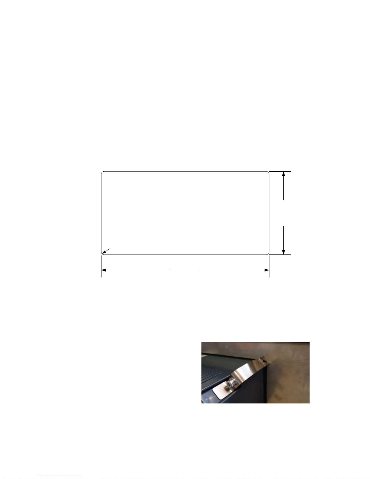
1. Insert the instrument in the panel cutout.
91mm +-1mm
3.58" +-0.04"
186mm +-1mm
7.32" +-0.04"
4x R max 5 mm
4x R max 0.2"
2. Place a bracket in the corner recession of the rear of the instrument and use the
M5 screw to secure it without tightening it.
3. Place the remaining three brackets and secure each with M5 screws. Tighten the
screws until the brackets start to press against the inside of the panel.
4. Make sure the tip of the brackets is resting against the panel on which the
instrument is mounted and not on the instrument plastic front. This might happen if
the cutout is large.
5. Check that the instrument is positioned
so that the blue front sealing is not
visible through the cutout which might
compromise the sealing properties.
6. When the instrument is properly
positioned tighten the screws 2 – 3
turns. Do not overtighten. Note that the
brackets are flexible.
7. Provide support for the cables to avoid
that strain is applied to the connectors.
Mounting bracket on
the panel mount model
Technical Manual
2-2
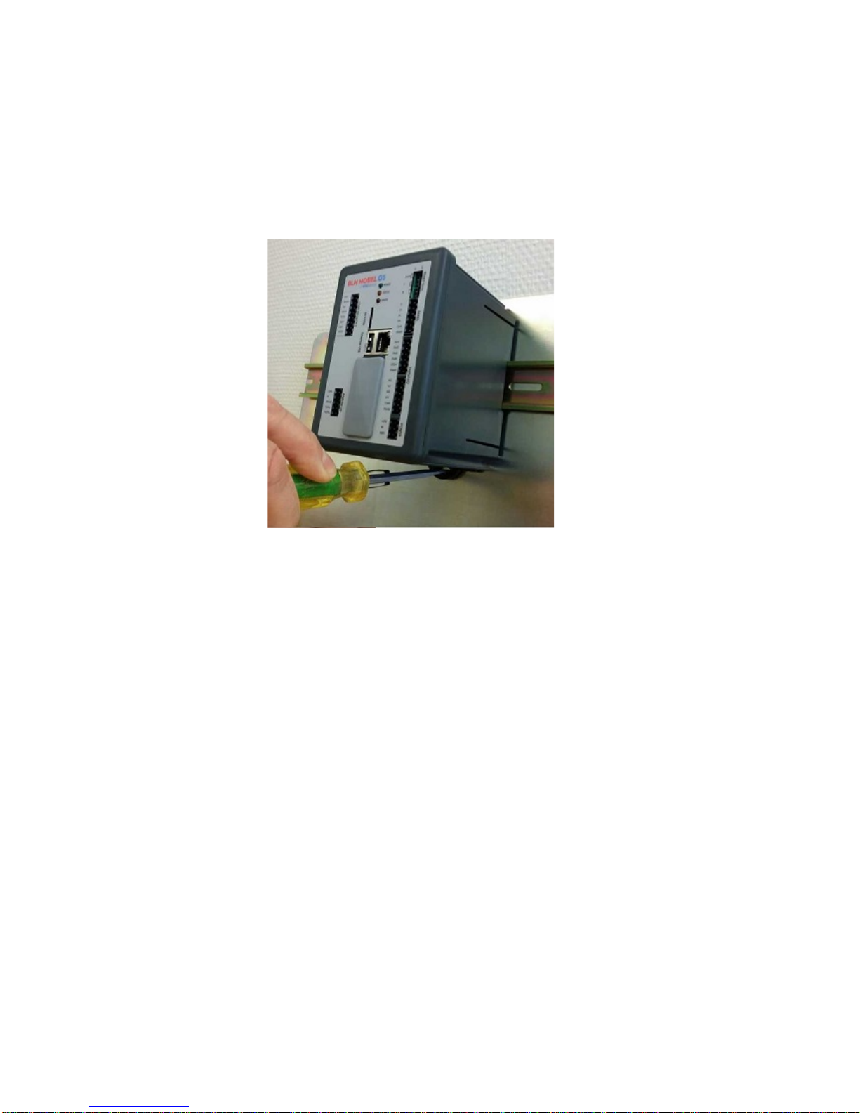
RM type instrument:
The unit snaps on to a DIN-rail. Place the unit with the front slightly tilted upwards on to
the DIN-rail. Make sure the hooks at the rear of the instrument enclosure are gripping
over the upper edge of the DIN rail. Push the unit down and towards the DIN-rail until it
snaps into locked position. If needed use a screwdriver to help open the latch to make
it snap on.
Use a screwdriver to open the latch if the unit is to be removed from the DIN-rail.

G5 Weighing Instrument
2-3
Electrical installation
The field wiring of the instrument shall be suitable to the environment
(e.g. chemically) in the end-user application.
Mains cables shall be separated and routed away from SELV or
SELV-E field wiring.
Field wiring installation shall comply with any national regulations, hereunder National
Electrical Code (NEC) for US and/or Canadian Electrical Code for Canada.
•A switch or circuit-breaker shall be included in the building installation.
•The switch shall be in close proximity to the equipment and
within easy reach of the operator
•The switch shall be marked as the disconnecting device for the equipment.
•The equipment switch or circuit-breaker employed as disconnecting device shall
comply with relevant requirements of IEC 60947-1 and IEC 60947-3.
The power supply for the instruments can be an external DC source for
G5-PM-S-DC-W and G5-RM-S-DC-W units or external AC mains for G5-PM-S-AC-W
units.
For electrical installation with DC supply, see section DC Supply.
For electrical installation with AC supply unit, see section AC Supply.
The voltage levels on connectors shall not exceed hazardous voltage
levels of 30 Vrms, 42.4 Vpeak or 60 Vdc under normal conditions. In
wet locations these voltage levels shall not exceed 16 Vrms, 22.6
Vpeak or 35 Vdc. This applies to all accessible parts.
Connection of cable shields
Shielded cables should be used to avoid EMI on the measurement signals or from
entering the instrument. Shields should be grounded in one point of the cable. Avoid
grounding via long and thin leads which will impair the shielding ability of the cable. The
preferable point of grounding is when the cable enters the metal cabinet housing the
instrument. There are a few ways of grounding the cable shield:
1. The absolutely best way of grounding the shield is by using EMI cable glands that
will provide a seamless protection against EMI.
2. Connect the shield to a ground strip inside the cabinet close to the entry point.
3. Connect the shield to a ground terminal inside the cabinet. Always keep the shield
all the way to the instrument.
WARNING
Make sure that that the power to the instrument is turned off before
any connections are connected to or disconnected from the
instrument.
Remove connector from instrument when tightening or loosening
screw terminal screws.
!
!
!
Technical Manual
2-4
The following applies to HW version 2 or later. See the System Information menu to
find out the actual HW version of the instrument. The shield of the load cell cable can
also be connected at terminal 26 to achieve best possible noise immunity of the LC
input. Note that terminal 26 is not the grounding point of the load cell cable but it will
extend the shield into the ground plane of the input circuit. Terminal 26 is not
connected to the ground of the instrument.
Communication
External computing devices connected to the communication interfaces of the
instrument have to comply with the standard, UL 60950.
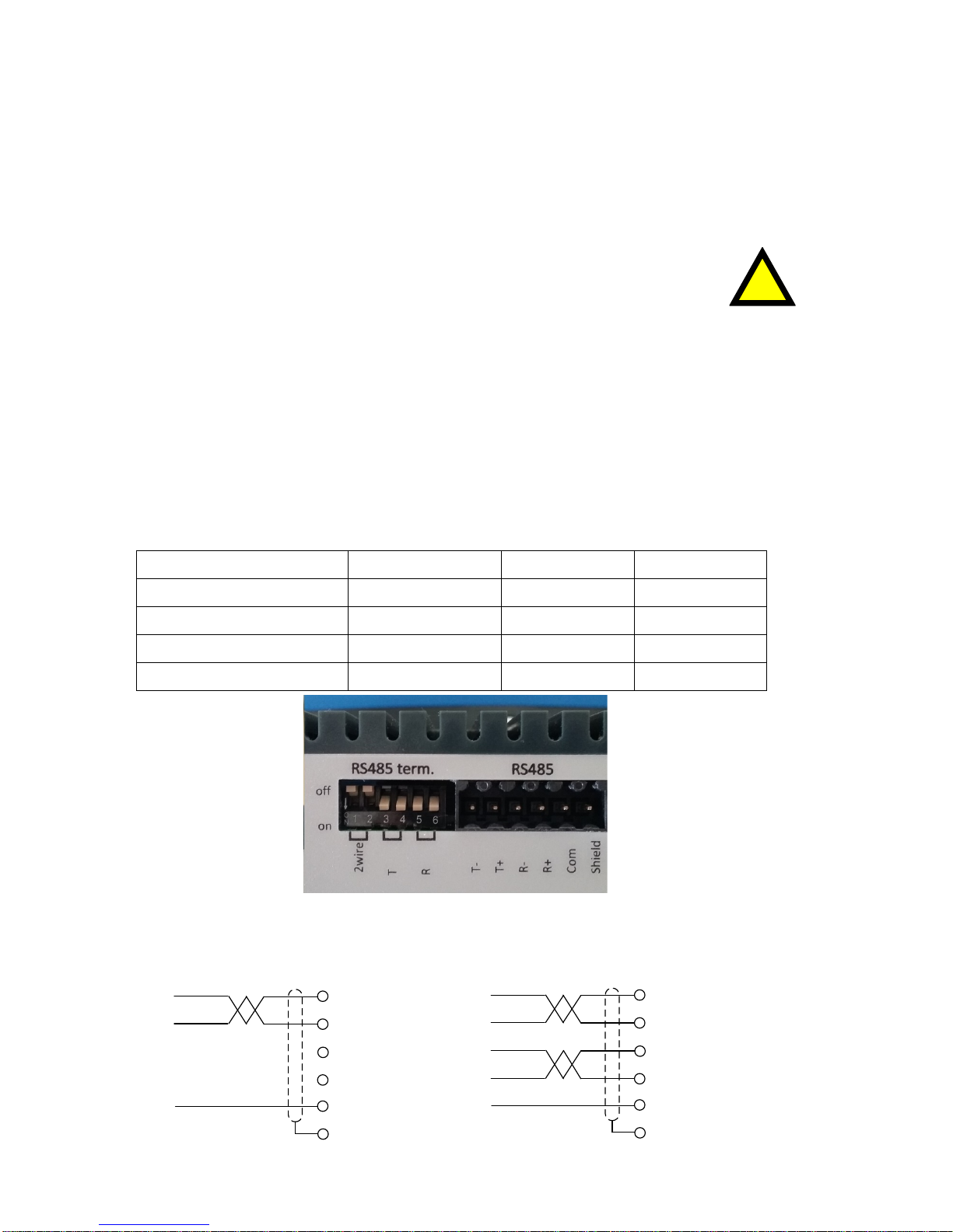
RS422/RS485
The serial communication is made for 2-wire or 4-wire with common 0 V. This is a
SELV/SELV-E circuit.
It can be used for serial communication to computer/PLC (Modbus RTU), a printer or
an external display. Connections are made to terminals 1 – 5. Shielded cable must be
used. Shield can be connected to terminal 6 unless grounded in other point.
The communication lines must be terminated in both ends. Termination switches are
set as shown in the table below:
DIP switch settings
2wire DIP-switches T DIP-switches R DIP-switches
2-wire with termination ON (x2) ON (x2) OFF (x2)
4-wire with termination OFF (x2) ON (x2) ON (x2)
2-wire without termination ON (x2) OFF (x2) OFF (x2)
4-wire without termination OFF (x2) OFF (x2) OFF (x2)
Example of DIP-switch settings.
4-wire with termination
!
1. Tx-
2. Tx+
3. Rx-
4. Rx+
5. Com
6. Shield
1. Tx-
2. Tx+
3. Rx-
4. Rx+
5. Com
6. Shield
RS485, 2-wire RS422, 4-wire

G5 Weighing Instrument
2-5
Field Bus
Slot for optional Fieldbus interface. Profibus DP-V1, DeviceNet, ControlNet,
EtherNet/IP and PROFINET are available. See separate Fieldbus option manual P/N
601402 for details.
USB
The USB connector is intended for USB memory only. This port has operational
insulation (from HW version 2). It should be considered as a SELV/SELV-E circuit.
USB Hub is not supported.
Ethernet
This is a SELV circuit. Use a category 5 cable to connect to a PC (point to point
connection) or to connect to other equipment through a switch, hub or router. Use an
electrically isolating network device if the instrument is being connected to the public
network.
DC supply
The output of the external DC source must be rated 24 V , ±15%
including fluctuations, min. 15 W. The DC source must provide Double
Insulation between Mains parts and 24 V SELV or SELV-E Circuit, and a
limited-energy circuit (maximum available current of 8 A). For the US
market this energy limit can be achieved with an ANSI/UL248-14 fuse rated 5A. For
other markets an IEC 60127 T type fuse rated 4A may also be used.
24 VDC power is connected to terminals 19, 20 and 21. The G5 instrument should be
powered by 24 V , connected according to the diagram below. To achieve functional
grounding, terminal 21 should be connected to ground.
See Technical data for input voltage ratings.
AC supply
Mains supply cable shall be separated and routed away from SELV or
SELV-E field wiring.
The branch circuit protection in the building installation must be rated
maximum 20 A. To achieve protective grounding, the PE conductor shall
be connected to protective earth.
Power inlet type C-14 according to IEC60939.
Use cable connector type C-13 according to IEC60320.
See Technical data for input voltage ratings.
19. +24 VDC
20. 0V
+
-21. PE
+24 VDC
power supply
!
!

Technical Manual
2-6
Load cell connection
Terminals 22 – 29, transducer connection and cabling should be handled with great
care to achieve good measurement of data. Transducer integrated cables may not be
shortened.
4-wire connection can be used if the transducer integrated cable is long enough to
be connected directly to a transducer input. With a 4-wire connection Sense+ must
be connected to Exc+ and Sense- must be connected to Exc-.
6-wire connection should be used if the integrated cable must be lengthened
or if several transducers should be connected to one transducer input.
The transducer input is insulated by operational insulation and the shield should be
connected to the most convenient ground/earth point. This can be the junction box
when using multiple transducers, at the cable entry to the enclosure where the G5 is
mounted or at the barrier ground when using Ex zener barriers.
Shield can be connected to terminal 26 if the instrument is of HW version 2 or later.
In the junction box SL-4 from BLH Nobel all necessary terminals and
interconnections are provided.
29. TEDS+ (NC)
22. Exc+
23. Sense+
24. Exc-
25. Sense-
26. Shield
27. Sign+
28. Sign-
E+
E-
S+S-
Junction box
Connection of transducer(s)
NOTE! Transducer cables must be routed at least 200 mm away from
230/400 V, 50/60 Hz power cables. By cables with other frequencies or
high power, an even wider distance is preferable.
G5 Weighing Instrument
2-7
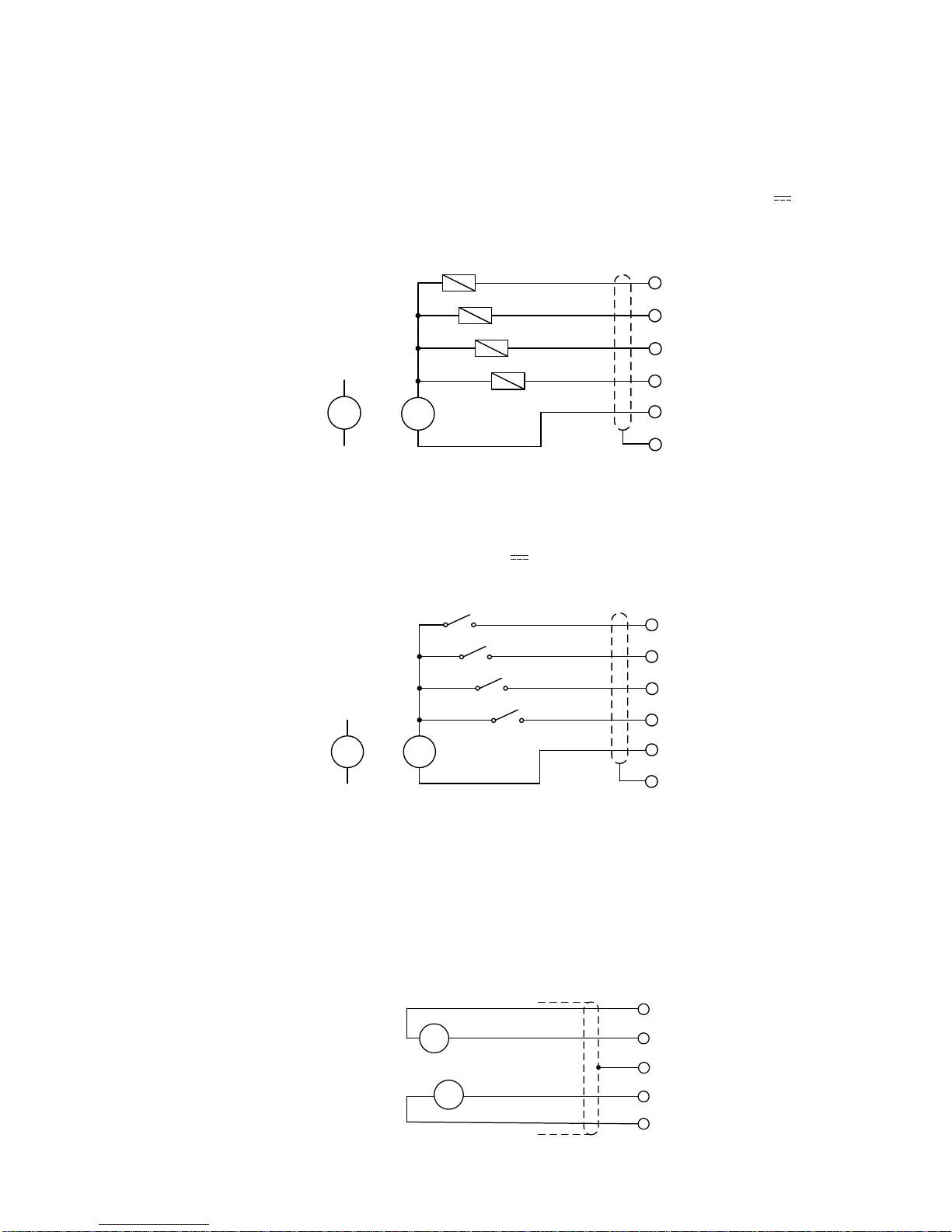
Solid state relay outputs
Digital outputs use terminals 7 to 10 with terminal 11 (OCom) as the common
connection. Four digital outputs are provided with contact rating given in Technical
data. Output functionality is set-up in the G5. External 24 VDC power supply must be
used. Note that either the positive or the negative pole of the voltage source (24 V )
can be connected to OCom (11).
Shielded cable/cables should be used and the shield can be connected to terminal 12 if
it’s not possible to ground it in another point.
7. Out 1
8. Out 2
9. Out 3
10. Out 4
11. OCom
+
-12. Shield
+
-
Alternative
connection
Digital inputs
Digital inputs use terminals 13 to 16 with terminal 17 (ICom) as the common
connection. Four digital inputs are provided, with functions that can be set in the G5
set-up. External 24 VDC power supply must be used. Note that either the positive or
the negative pole of the voltage source (24 V ) can be connected to ICom (17).
Shielded cable/cables should be used and the shield can be connected to terminal 18 if
it’s not possible to ground it in another point.
13. In 1
14. In 2
15. In 3
16. In 4
17. ICom
+
-
18. Shield
+
-
Alternative
connection
Analog input and analog output
Terminals 38 (Vi) and 39 (Comi) are used for the +-10V auxiliary analog
input of the instrument. The analog output is connected to terminals 41
(Como and output signal to terminal 42 (Vo1/Io1). The analog output is either
voltage or current loop. Como and Comi are internally connected.
Shielded cable/cables should be used and the shield can be connected to the shield
terminal 40 if it’s not possible to ground it in another point.
38. Comi
39. Vi
40. Shield
41. Como
42. Vo1/Io1
+
-
V/A
Analog input: +-10V
Analog output:

Technical Manual
2-8
Front panel
Display
At normal operation the instrument displays weight value(s) and, in some cases,
the gross weight as a graphic bar. Together with the weight value additional information
such as preset tare, status for the level supervision can also be displayed. This is
configured with parameters.
If an instrument error occurs, the weighing function is stopped and the instrument
switches over to Error mode, indicating a code for the error at the display window.
If there is a scale error this is indicated with error information that replaces the weight
information on the screen. The instrument can also display a Main menu with sub
menus for display of actual data and entry of new data.
Function keys
Just below the display there are four function keys, F1 to F4, and with the actual key
functions indicated at the lower line of the display. When there is a text above a key,
that key has the corresponding function. To select a function, press the membrane
panel button (F1 to F4) below the display.
Symbol keys
At the bottom of the front panel there are four keys, marked with the weighing
symbols for ZERO, TARE, GROSS/NET, PRINT plus keys marked START and
STOP. A brief description of these keys is given in the table below.
Front panel of the G5 instrument with color display, four function keys below the display, six
application specific keys, numerical keypad, joystick keypad (arrow keys), ESC, Backspace,
DEL and Enter keys.
In addition there is an INFO key that is used to access the instruments menu system.

G5 Weighing Instrument
2-9
Key Name Function
0
ZERO Setting the gross weight value to zero (provided the value
is in the zeroing range: -1 % to +3 % of the capacity) and
setting the auto tare value to zero.
T
TARE
Taring, i.e. entry of the gross weight as auto tare value and
display of net weight zero. Depending on actual setting taring
may be prevented if ‘Motion’ is displayed.
BN
GROSS/NET
Toggling between display of gross weight and net weight.
Net weight can be displayed only if a tare weight has been
entered or acquired.
PRINT Printing of the displayed weight value on a connected printer
according to parameter settings.
Printing the accumulated weight when menu Accumulated
Weight is shown.
START Not used in this program version.
STOP Not used in this program version.
Numerical keys
The digit keys, including keys with minus sign and decimal point, are used for entry and
editing of numerical parameter values.
Miscellaneous keys
An Enter key on the panel is used to open a selected menu, finish the entry of a value,
etc.
The four arrow keys are used to navigate in the menu system and to toggle between
selections.
The ESC, DEL and Backspace keys are used for editing values, toggling between
selections and so on.
The INFO key is used to enter the instrument menu system. Note that this key can only
be used when the weight display is shown.

Technical Manual
2-10
This manual suits for next models
2
Table of contents
Other BLH NOBEL Accessories manuals


