Blindleistungsregler TSM-AT User manual
Dynamic Power Factor Correction
Thyristor Module TSM-AT
General:
Conventional systems for power factor correction are used to optimize the power factor and
reduce the level of harmonics in the net. The usage of new technologies in modern industry has
negative impacts on electrical power quality of the main supply networks, eg. frequent high load
fluctuations and harmonic oscillation. Excessive currents, increased losses and flickering will not
only influence the supply capacity but will also have a significant impact on the operation of
sensitive electronic devices. The solution for this are dynamic power factor correction systems.
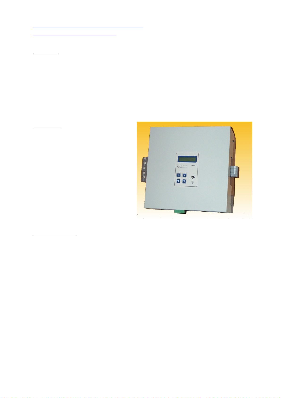
With the TSM-AT module we provide the main component – „electronic switch“ – for dynamic
power factor correction. The TSM-AT is a fast electronically controlled, self-observing thyristor
switch for capacitive loads up to 100 kVAr, which is capable to switch PFC capacitors within a few
milliseconds as often as required.
Features:
-Real 3-phase switching
(usage only with single-phase capacitors
L-N)
-Output up to 120 kVAr at 690 V
-Usage for PFC-systems with and without
reactors (programmable)
-Connected load (output) programmable
-Easy programming for the individual
application via multi-lingual plain
language display
-Indication of all relevant parameters of
the grid
(voltage, current, temperature...)
-Alarm output and error message storage
.
Technical Data
Voltage max. 690V ( 3 x 400V L-N )
Max.power up to 120 kVAr at 690 V
up to 100 kVAr at 525 V
Parameter setting nominal voltage, degree of detuning, overcurrent, alarm temperature,
via display frequency, error message storage, delay time during cascading
Control features permanent monitoring of net voltage, phasing, capacitor current,
module temperature. Malfunction shown in plain language and evaluated;
former errors are stored in an error message storage
Display 3-phase indication of net voltage and capacitor current
temperature values and all parameters programmed can be retrieved
Controlling 10-24 VDC , internally DC-insulated; manual operation possible
Power circuit connection: three-pole via clamp (25qmm)
Losses Pv(in W)= 3.0 * I (in A) at 690V / 100 kVAr approx. 240W)
Fuses electronic fuse „superfast“ 160 A (NH00)
Dimensions 300 x 300 x 200 mm (w x h x d)
Description
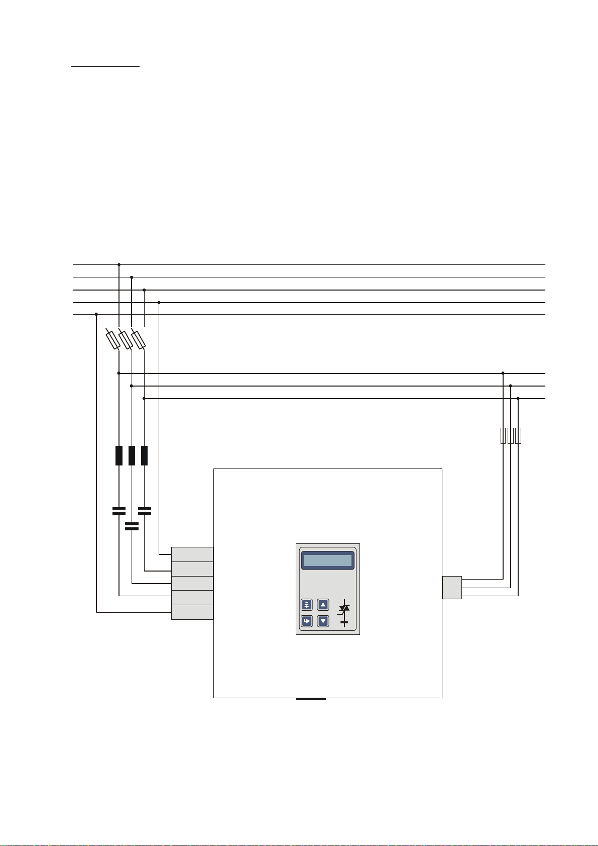
TSM-AT Thyristor-switches are used for dynamic PFC equipment. The connection is
made via three phases according to picture 1. Take care for a correct phase sequence!
(If the phase-sequence is not correct, the module will be blocked.)
Main-fuses have to be electronic-fuses (superfast) for protection of the semiconductor
components. Please observe the correct fuse rating.
Activation of the modules is done by a 10-24 VDC signal (by a dynamic reactive power
regulator) which is connected to terminals X3:1 and 2.
For cascading of several modules (for increase of the kVAr-output) parallel-connection is
possible. For additional modules, programming of delay time is possible.
Pic. 1
C3
C2
C1
3x4AT
Control-Input:
1 activation signal - 12V
2 activation signal +12V
3 and 4 alarm output (zero-potential) max 250V,6A
5 and 6 n.c.
Ausschnitt
65x20 mm
T hy ris tor Po wer Swi tch
for capa citors
T hy ris torsch alte r für
Leistungskondensa toren
TSM-AT
ENTER
Display
Program
Service
1 2 3 4 5 6 7
L1
L2
L3
N
SL
Thyristor-switch TSM-AT
here: for 690V grid
3xC - star-connection
Fuses for power supply
NH00, superfast
Fuse for
controlvoltage
N
C3
C2
C1
SL
L1
L2
L3
Putting into operation
After connection of the module according to above instructions, it can put into
operation.
After applying up of net voltage (inserting of the branch fuse) the module is ready for
operation. No triggering signal should be connected! Charging of the capacitors is
indicated in the display by a momentarily blinking diode-symbol. The permanent diode-
symbol indicates the operational readiness of the TSM-AT. (In case a triggering signal is
active at the input of the TSM, this is indicated by the letter “X” in the display next to
the diode-symbol.
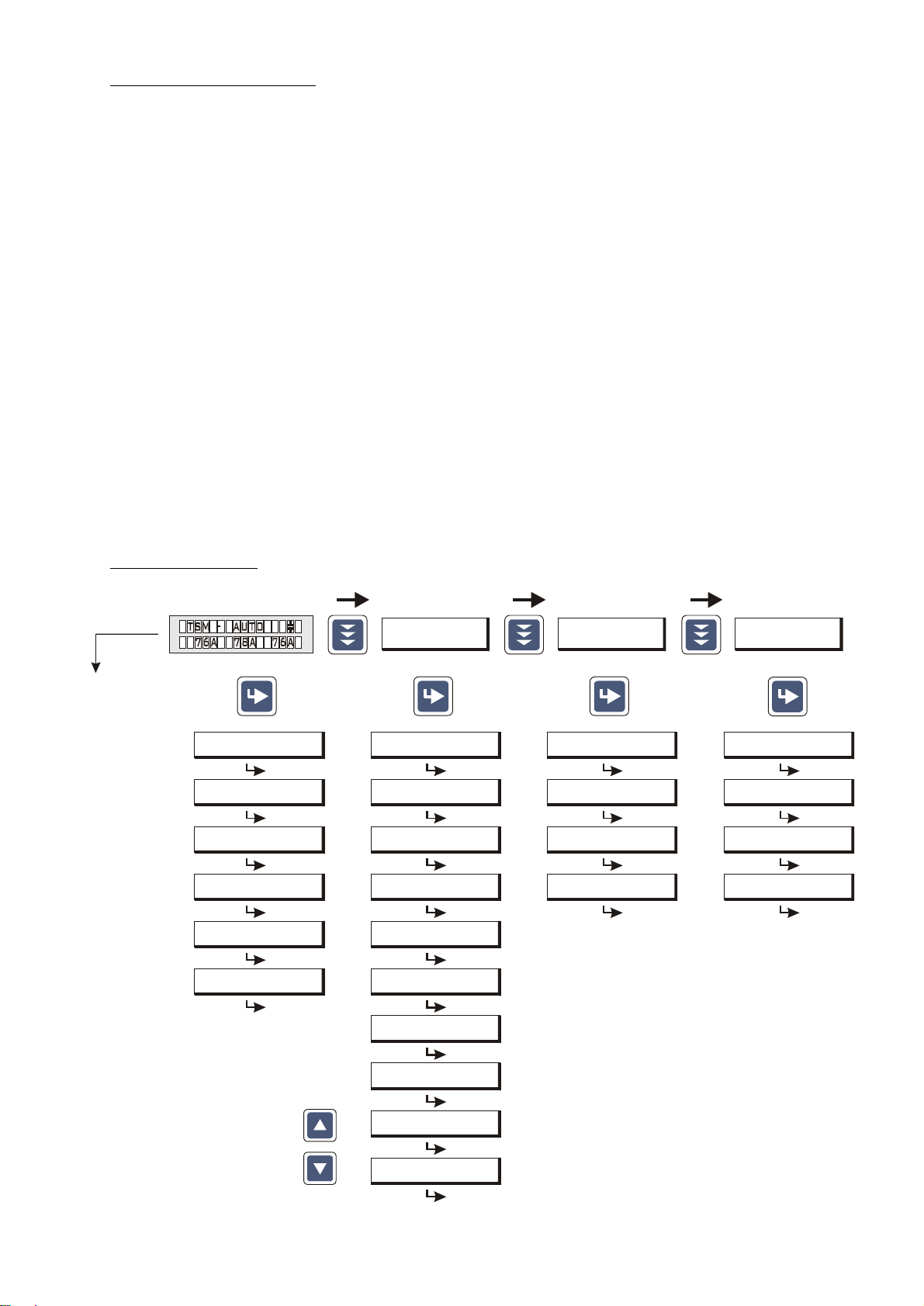
The menu item “programming” is activated via the menu-button. The parameterizing of
the module is done here (see operation diagram). Change of values is done via the
arrow buttons ; safe with “ENTER”. After entry of all parameters, the module is
ready for operation (automatic operation).
During automatic operation, the module can be turned ON and OFF via arrow buttons
manually (manual operation). The operation mode is indicated in the display
(AUTO/HAND).
The ON-mode of the module is indicated in the display by a capacitor-symbol.
Operating diagram
Programming Expert mode
Fault memory
1 PASSWORD ????
( 0*** )
2 BASIC SETTINGS NEW
[ NO ]
3 PROGRAM LOCK
[ NO ]
4 SWITCHING ON-DELAY
[ 0 ] PERIODS
1 VOLTAGE
400V 400V 400V
2 TEMPERATURE
45°C
3 MODUL ADRESS
1
4 MODUL-VOLTAGE
5 CURRENT
SOFTWARE VERSION
TSM VE 1.0
1 LANGUAGE
[ ENGLISH ] 1. ERROR L1 L2 L3
UNDERVOLTAGE
2. ERROR
up to. 16 ERRORs
Delete ERROR ?
[ NO ]
2 MODUL ADRESS
[ 1 ]
8 ALARM RELAY
[ ERROR ]
CONTRAST
**** 9 ****
BASIC SETTINGS
[ NO ]
Programming:
Changing of
values by
buttons
bei Störung erfolgt
Anzeige “TSM-ERROR”
4 VERDROSSELUNG
[ 7 ] %
5 OVERCURRENT
[ 30 ] %
7 FREQUENCY
[ 50 ] Hz
6 TEMP-ALERT
[ 80 ] °C
3 POWER
[ 50 ] kvar
BACK TO 2
BACK TO 1
Automatikbetrieb
BACK TO 1
BACK TO 1
Following ERROR-messages are possible:
- UNDERVOLTAGE
- OVERVOLTAGE
- OVERCURRENT
- UNDERCURRENT
- THYRISTOR FAULT
- TEMPERATURE FAULT (Sensor)
- OVERTEMPERATUR

Control functions / Alarm messages
The TSM-AT observes permanently:
- voltage (availability & value)
- phase sequence
- capacitor rated current
- temperature of the power switches
When voltage, current or temperature-problems occur, the TSM turns-off and shows the
Error at the display.
At the same time, the error-description is stored in the error storage register (max. 16).
In the menu item “Error storage” the errors can be read out. So it is possible to
recognize also short-term malfunctions afterwards.
By supervising the capacitor current it is possible to identify dangerous operating
conditions, such as harmonic distortion. High current harmonics may cause the
destruction of the connected PFC capacitor. Over currents are measured by an
integrated measuring system. The module turns-off as long as the overload exists.
The highly advanced measuring circuit for self-observing of the thyristor switch protects
the capacitor and the application as well.
The alarm-signal of the temperature trigger switches-off the corresponding capacitor
branch. After disconnection the thyristor switch will cool down again. If the temperature
drops below the preset threshold value, the module will reconnect.
Errors are indicated via relay contact and visualized via Display.
All error messages are summarized as a centralized error message and the output
occurs via a relay contact. In the programming menu it can be selected if this output
should be stored or whether it should only be displayed during the malfunction.
NOTE THE FOLLOWING INSTRUCTIONS !
The power capacitors are permanent on high voltage ( up to 1500 VDC )
EVEN IF THE TSM-AT IS SWITCHED OFF !!
Please follow the instructions:
Don’t touch live parts in the PFC equipment !!
Warning signs in the equipment required!!
Wait 10 minutes after the main switch is turned off – until the voltage in the
system is down to an uncritical value.
In systems (690V grid) you need single-phase capacitors with a min. voltage of
440V! All capacitors have to switch in star-circuit. (L-N)
In systems (525V grid) you need single-phase capacitors with a min. voltage of
380V ! All capacitors have to switch in star-circuit. (L-N)
In dynamical PFC systems discharge reactors cannot be used!
( this would be a shortcut of the high-voltage DC )
In PFC systems without filter circuit reactors current limiting reactors are required (
e.g. BD-100 ) for the TSM.
For short circuit protection superfast electronic fuses for protection of the thyristor
are required, standard HRC fuses are not suitable
Popular Control Unit manuals by other brands


Bray
Bray McCANNALOK Series Installation, operation and maintenance manual

Siemens
Siemens SIRIUS ACT 3SU18 N Series Original operating instructions

King gates
King gates Star 2230 instruction manual

Long Range Systems
Long Range Systems Butler II Quick setup & operation

Hayward
Hayward GLX-PCB-PRO Replacement manual

Danfoss
Danfoss VLT HVAC Drive FC 102 instruction manual