Sit 630 Eurosit Technical manual

L
630
EUROSIT
Read the instructions before use. This control must
be
installed
in
accordance with the rules
in
force.
L
English
.-.
T
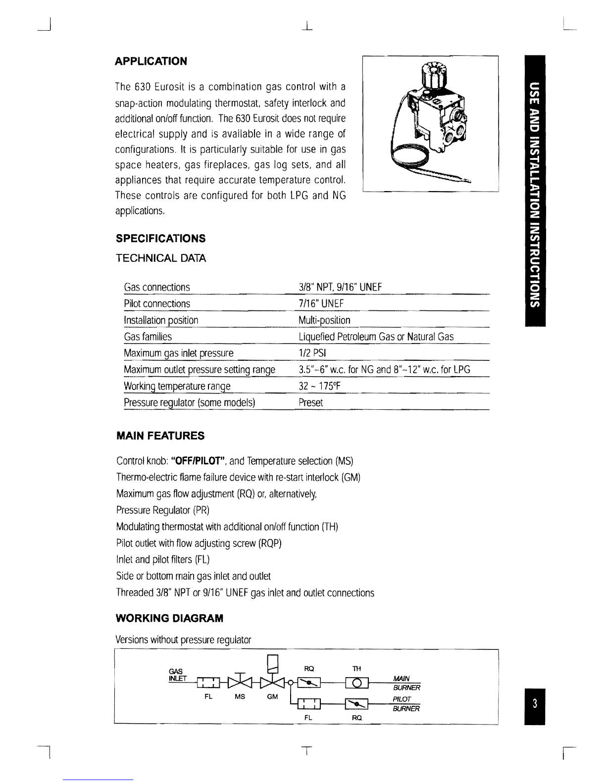
APPLICATION
The
630
Eurosit
is
a
combination
gas
control
with
a
snap-action
modulating
thermostat,
safety
interlock
and
additional
onloff
function.
The
630
Eurosit
does
not
require
electrical
supply
and
is
available
in
a
wide
range
of
configurations.
It
is
particularly
suitable
for
use
in
gas
space
heaters,
gas
fireplaces,
gas
log
sets,
and
all
appliances
that
require
accurate
temperature
control.
These
controls
are
configured
for
both
LPG
and
NG
applications.
SPECIFICATIONS
TECHNICAL
DATA
Gas
connections
3/8"
9/16"
UNEF
Pilot
connections
7/16"
UNEF
Installation
position
Multi-position
~--------------------~-------------------------
Gas
families
Petroleum
Gas
or
Natural
Gas
Maximum
1/2
PSI
Maximum
outlet
pressure
setting
range
3.5"
-6"
w.c.
for
NG
and
8"-12"
w.c.
for
LPG
Working
temperature
range
32
-
175°F
Pressure
regulator
(some
models)
Preset
MAIN FEATURES
Control
knob:
"OFF/PILOT",
and
Temperature
selection
(MS)
Thermo-electric
name
failure
device
with
re-start
interlock
(GM)
Maximum
gas
How
adjustment
(RQ)
or,
alternatively,
Pressure
Regulator
(PR)
Modulating
thermostat
with
additional
onloff
function
(TH)
Pilot
outlet
with
How
adjusting
screw
(RQP)
Inlet
and
pilot
filters
(FL)
Side
or
bottom
main
gas
inlet
and
outlet
Threaded
3/8"
NPT
or
9/16"
lINEF
gas
inlet
and
outlet
connections
WORKING DIAGRAM
Versions
without
pressure
regulator
MAIN
BURNER
PILOT
BURNER
FL
RQ
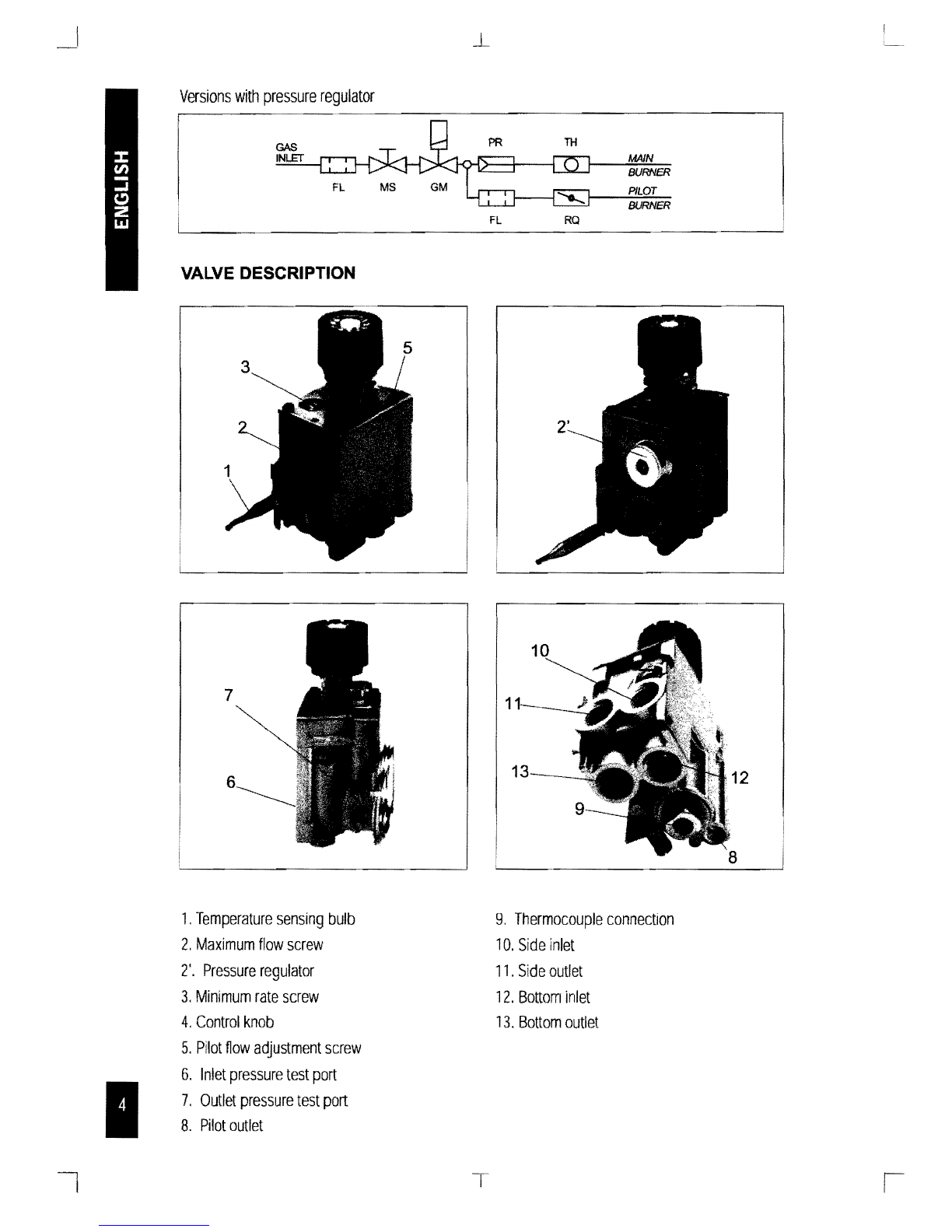
Versions
with
pressure
regulator
TH
~
MAJN
----:::eu;"='RN"-::'S=R
FL MS GM '0....
t-_....:R~IL~OT~
BURNER
FL
RQ
VALVE DESCRIPTION
1.
Temperature
sensing
bulb
2.
Maximum
flow
screw
2'.
Pressure
regulator
3.
Minimum
rate
screw
4.
Control
knob
5.
Pilot
fiow
adjustment
screw
6.
Inlet
pressure
test
port
7.
Outlet
pressure
test
port
8.
Pilot
outlet
9.
Thermocouple
connection
10.
Side
inlet
11.
Side
outlet
12.
Bottom
inlet
13.
Bottom
outlet

L
THERMOSTAT REGULATION SPECIFICATIONS
Thermostat
Features
Thermostatic
Range
55.100
of
55.118
of
a
2.7
4.5
i b c
I
2.7
1.B
4.5
2.7
b
Temperature
c a
eSTOP:
Do
not
install,
replace,
or
in
any
way
modify
the
gas
valve
or
the
appliance,
unless
CERTIFIED
and
QUALIFIED
as
a
Gas
Appliance
Service
Technician
on
the
appliance
this
valve
is
used
on.
READ
AND
FOLLOW
ALL
INSTRUCTIONS,
INSTALLATION
Valve
configuration
inspection
Min
Rate
Screw
The
630
Eurosit
can
have
one
inlet
and
one
outlet
plugged.
Inspect
the
control
to
determine
which
inlet
and
outlet
are
plugged.
The
plugs
use
o·ring
seals
and
are
made
of
brass,
The
replacement
control
must
have
the
same
inlet
and
outlet
plugged
as
the
original
control.
Use
a
5/16"
Allen
key
to
remove
and
tigten
the
plug.
The
replacement
630
Eurosit
has
an
On/Off
modulating
plug
(fig,
A)
installed.
To
achieve
similar
performance
as
the
original
control.
remove
the
plug
in
the
replacement
control
using
a
Flathead
Screwdriver
and
set
aside.
Remove
the
Min
Rate
Screw
(fig.
B)
from
the
original
control
and
install
it
into
the
replacement
control
in
the
same
location.
When
installation
of
this
product
begins."
1.
Read
all
of
these
instructions
carefully.
Failure
to
follow
instructionscould
damage
the
product
or
cause
a
dangerous
condition.
2.
Check
the
ratings
given
in
the
instructions
and
on
the
appliance
to
make
certain
that
the
control
is
suitable
for
your
application,
3.
All
operations
of
installation,
calibration,
conversion
and
regulation
must
be
undertaken
exclusively
by
qualified
personnel
following
the
instruction
speCified
in
this
catalog
and
those
in
the
instruction
manual
of
the
appliance
in
which
the
valve
is
installed.
4,
After
installation
is
complete,
verify
that
the
appliance
operates
as
indicated
in
these
instructions.
T
_I
L
WARNING:
Fire
or
Explosion
Hazard.
Can
cause
property
damage,
severe
iruury
or
death.
Follow
these
instructions
completely.
1.
Turn
off
gas
supply
at
the
appliance
service
valve
before
installation,
and
perform
a
Gas
Leak
Test
after
the
installation
is
completed.
2.
Always
install
the
sediment
trap
in
the
gas
supply
line
to
prevent
contamination
of
the
gas
control.
3.
Do
not
force
the
control
knob.
Use
only
your
hand
to
turn
the
knob.
If
the
knob
does
not
move
by
hand,
the
valve
should
be
replaced
by
a
trained
service
technician.
WARNING:
Oxygen
Depletion
Hazard.
Can
cause
injury
or
death
by
asphyxiation.
00
not
use
valves
for
vented
appliances
on
unvented
or
vent
free
appliances.
00
not
use
valves
for
unvented
or
vent
free
appliances
on
vented
appliances.
&.
CAU'nON
Electrical
shock
or
equipment
damage
hazard.
Can
shock
individuals
or
short
equipment
circuitry.
Make
sure
to
disconnect
all
electrical
supplies
before
beginning
the
installation
process.
IMPORTANT
-
These
gas
controls
are
shipped
with
anti-contamination
seals
over
inlets
and
outlets.
-
Do
not
remove
the
seals
until
ready
for
connection
to
piping.
-
Appliance
manufacturer's
instructions
supercede
any
instructions
listed
in
this
instruction
book.
INSTALL PIPING TO
GAS
VALVE
All
piping
must
comply
with
local
codes
and
ordinances
or
with
the
National
Fuel
Gas
code
(ANSI
Z223.1
NFPA
No.
54)
whichever
applies.
Tubing
installation
must
comply
with
approved
standards
and
practices.
Use
appropriately
sized
fittings
when
connecting
aluminum
tubing
to
the
pilot
outlet.
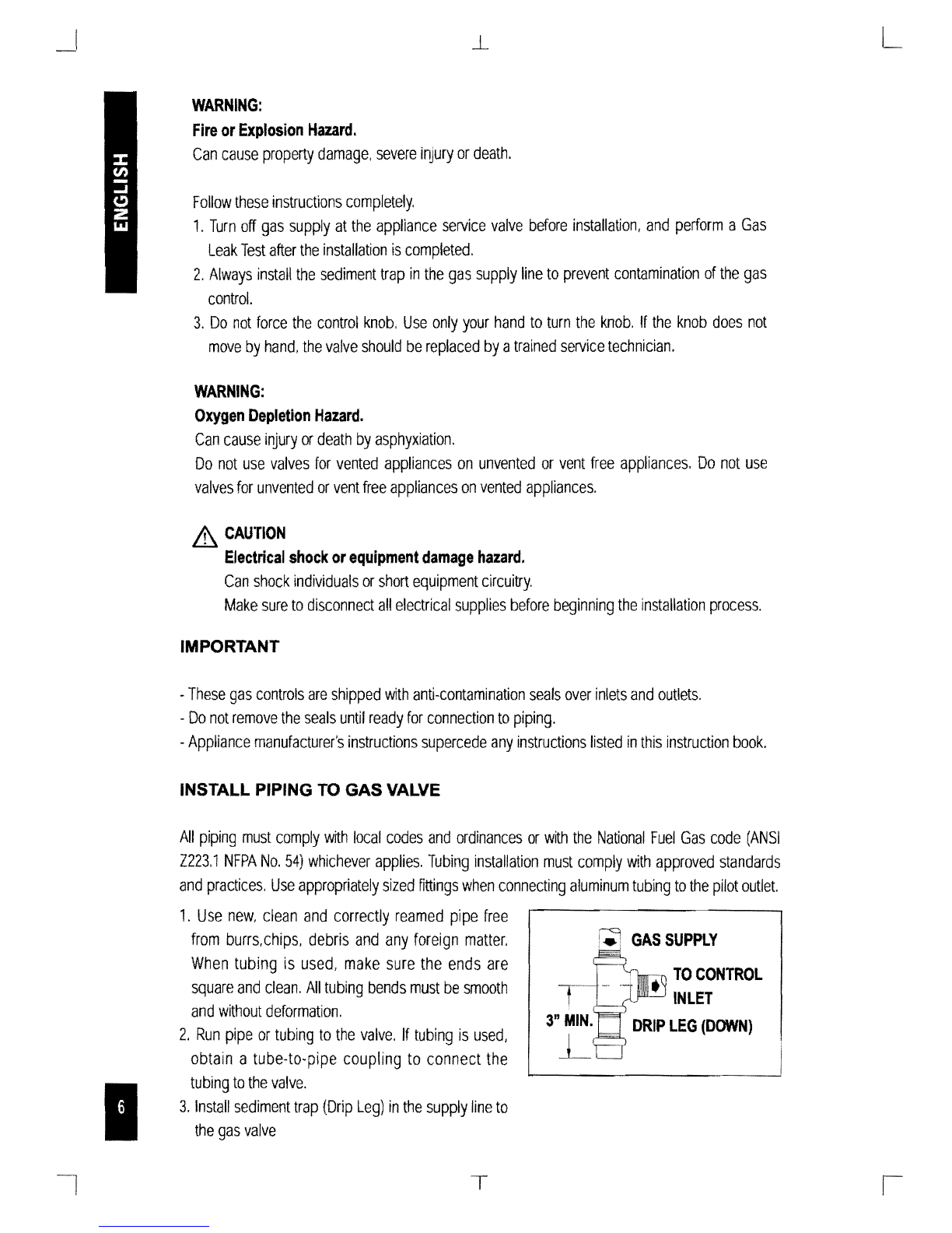
1.
Use
new,
clean
and
correctly
reamed
pipe
free
from
burrs,chips,
debris
and
any
foreign
matter.
When
tUbing
is
used,
make
sure
the
ends
are
square
and
clean.
All
tubing
bends
must
be
smooth
and
without
deformation.
2.
Run
pipe
or
tubing
to
the
valve.
If
tubing
is
used,
obtain
a
tube-to-pipe
coupling
to
connect
the
tubing
to
the
valve.
3.
Install
sediment
trap
(Drip
Leg)
in
the
supply
line
to
the
gas
valve
~
GAS
SUPPLY
INLET
•
TOCONTROL
T
3"
MIN.
DRIP
LEG
(DOWN)
L
T
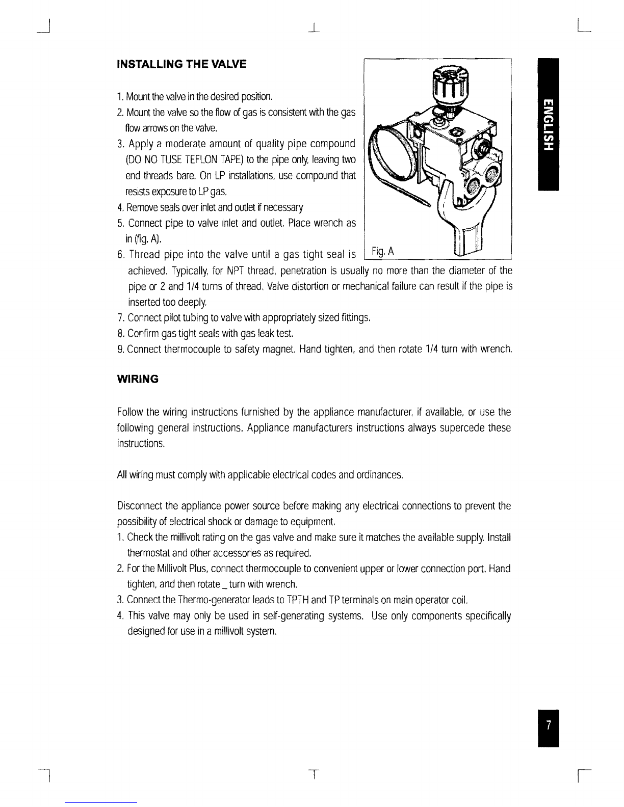
INSTALLING THE VALVE
1.
Mount
the
valve
in
the
desired
position.
2.
Mount
the
valve
so
the
flow
of
gas
is
consistent
with
the
gas
flow
arrows
on
the
valve.
3.
Apply
a
moderate
amount
of
quality
pipe
compound
(DO
NO
TUSE
TEFLON
TAPE)
to
the
pipe
only,
leaving
two
end
threads
bare.
On
LP
installations,
use
compound
that
resists
exposure
to
LP
gas.
4.
Remove
seals
over
inlet
and
outlet
if
necessary
5.
Connect
pipe
to
valve
inlet
and
outlet.
Place
wrench
as
in
(fig.
A).
6.
Thread
pipe
into
the
valve
until
a
gas
tight
seal
is
achieved.
Typically.
for
NPT
thread,
penetration
is
usually
no
more
than
the
diameter
of
the
pipe
or
2
and
1/4
turns
of
thread.
Valve
distortion
or
mechanical
failure
can
result
if
the
pipe
is
inserted
too
deeply.
7.
Connect
pilot
tUbing
to
valve
with
appropriately
sized
fittings.
8.
Confirm
gas
tight
seals
with
gas
leak
test.
g.
Connect
thermocouple
to
safety
magnet.
Hand
tighten,
and
then
rotate
1/4
turn
with
wrench.
WIRING
Follow
the
wiring
instructions
furnished
by
the
appliance
manufacturer,
if
available,
or
use
the
following
general
instructions.
Appliance
manufacturers
instructions
always
supercede
these
instructions.
All
wiring
must
comply
with
applicable
electrical
codes
and
ordinances.
Disconnect
the
appliance
power
source
before
making
any
electrical
connections
to
prevent
the
possibility
of
electrical
shock
or
damage
to
equipment.
1.
Check
the
millivolt
rating
on
the
gas
valve
and
make
sure
it
matches
the
available
supply.
Install
thermostat
and
other
accessories
as
required.
2.
For
the
Millivolt
Plus,
connect
thermocouple
to
convenient
upper
or
lower
connection
port.
Hand
tighten,
and
then
rotate
_
turn
with
wrench.
3.
Connect
the
Thermo-generator
leads
to
TPTH
and
TP
terminals
on
main
operator
coil.
4.
This
valve
may
only
be
used
in
self-generating
systems.
Use
only
components
specifically
designed
for
use
in
a
millivolt
system.
L
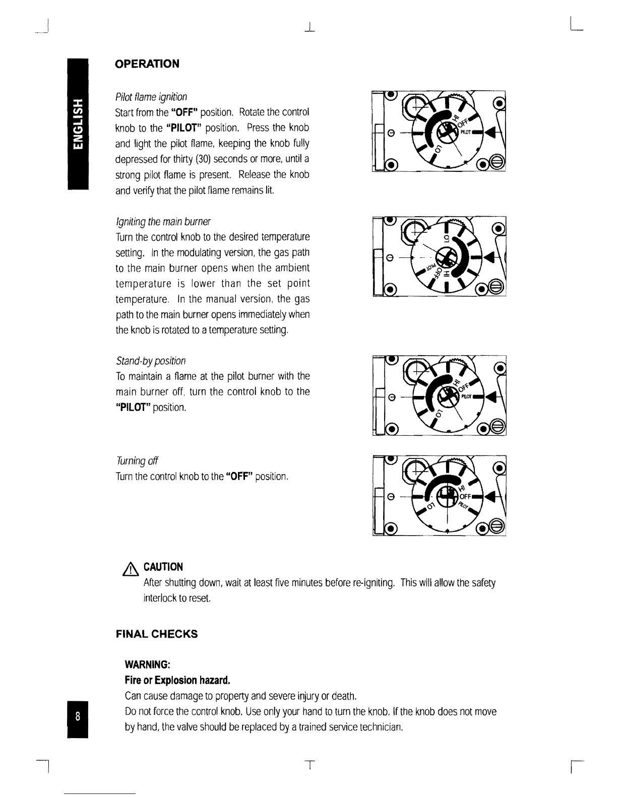
OPERATION
Pilot
flame
ignition
Start
from
the
"OFF"
position.
Rotate
the
control
knob
to
the
"PILOT"
position.
Press
the
knob
and
light
the
pilot
name.
keeping
the
knob
fully
depressed
for
thirty
(30)
seconds
or
more,
until
a
strong
pilot
flame
is
present.
Release
the
knob
and
verify
that
the
pilot
flame
remains
lit.
Igniting
the
main
burner
Turn
the
control
knob
to
the
desired
temperature
setting.
In
the
modulating
version.
the
gas
path
to
the
main
burner
opens
when
the
ambient
temperature
is
lower
than
the
set
point
temperature.
In
the
manual
version,
the
gas
path
to
the
main
burner
opens
immediately
when
the
knob
is
rotated
to
a
temperature
setting.
Stand-by
position
To
maintain
a
flame
at
the
pilot
burner
with
the
main
burner
off.
turn
the
control
knob
to
the
"PILOT"
position.
Turning
off
Turn
the
control
knob
to
the
"OFF"
position.
&
CAUTION
After
shutting
down,
wait
at
least
five
minutes
before
re-igniting.
This
will
allow
the
safety
interlock
to
reset.
FINAL CHECKS
WARNING:
Fire
or
Explosion
hazard.
Can
cause
damage
to
property
and
severe
injury
or
death.
Do
not
force
the
control
knob.
Use
only
your
hand
to
turn
the
knob.
If
the
knob
does
not
move
by
hand,
the
valve
should
be
replaced
by
a
trained
service
technician.
PERFORM GAS LEAK TEST
WARNING:
Stand
away
from
the
main
burner
while
lighting.
Hidden
gas
leaks
can
cause
Hashbacks
in
the
appliance
area.
Check
for
gas
leaks
with
rich
soap
and
water
solution
any
time
work
is
done
on
a
gas
system.
GAS LEAK TEST
o
Using
a
solution
of
soapy
water,
paint
the
piping
connections
which
are
upstream
of
the
control.
The
presence
of
bubbles
indicate
a
gas
leak
is
present.
o
If
a
leak
is
detected,
tighten
the
pipe
connections
and
repeat
leak
test.
o
Light
the
main
burner.
o
With
the
main
burner
in
operation,
paint
all
piping
connections
from
the
valve
with
a
soap
and
water
solution.
o
If
another
leak
is
detected,
tighten
the
connection.
o
If
after
tightening
the
connections
the
leak
is
still
present.
replace
the
leaky
part
and,
or
valve.
Shut
off
the
main
gas
supply
before
attempting
replacement
of
parts
or
the
valve.
o
Using
the
soap
and
water
solution
test
the
pressure
test
ports
and
min
rate
screw
to
verify
that
no
leak
is
present.
o
If
a
leak
is
detected
tighten
the
screw
and
retest.
-
If
after
tightening
the
pressure
test
port
or
min
rate
screw
the
leak
is
still
present
shut
off
main
gas
supply
and
replace
the
valve.
SHUTDOWN PERFORMANCE TEST
WARNING:
Fire
or
Explosion
Hazard.
Can
cause
severe
irtiury
or
death.
Perform
the
safety
shutdown
check
any
time
work
is
done
on
a
gas
system.
1.
Place
the
appliance
in
operation.
The
pilot
and
main
burners
should
be
lit.
2.
Place
gas
control
knob
in
"PILOT"
position.
Main
burner
should
extinguish
and
pilot
should
remain
lit.
3.
Extinguish
pilot
Hame.
Pilot
gas
safety
shutoff
proves
complete
shutdown
due
to
the
fact
the
safety
shutoff
valve
prohibits
main
burner
and
pilot
gas
How.
4.
Wait
at
least
five
minutes
for
the
safety
magnet
to
reset
and
residual
gas
to
clear
from
the
combustion
chamber.
S.
Relight
pilot
burner
and
operate
the
system
through
one
complete
cycle
to
ensure
all
functions
operate
correctly.
MAINTENANCE
This valve
is
not field serviceable. There are
no
replaceable parts.
Do
not
disassemble,
or
attempt replacement of any parts
on
or
in
the valve.
Improper adjustment or tampering with settings can result in severe
injury or death.
ACCESSORIES
3/~sealing
pl~g
fo!
unused
inlets
and
outlets
(Typically
2
per
valve)
0.972.058
for
pilot
burner
connections
for
1/4"
0.958.042
Disc
adaptor
for
remote
control
0.997.209
Other
accessories
available
on
request
T
Other manuals for 630 Eurosit
2
Table of contents
Other Sit Control Unit manuals


Popular Control Unit manuals by other brands


Telcoma
Telcoma T201 Instructions for installing

Watts
Watts AMES 960GD-15-17 Installation, operation and maintenance

jbc
jbc DMU instruction manual

QUNDIS
QUNDIS Q Water 5.5 Mounting and installation instructions

Advantech
Advantech PCM-3347 Series user manual

Azbil
Azbil Actival VY5302C Specifications & instructions