manuals.online logo
Brands
  1. Home
  2. •
  3. Brands
  4. •
  5. Parker
  6. •
  7. Control Unit
  8. •
  9. Parker CK5-DN User manual

Parker CK5-DN User manual

1
Refrigerating Specialties Division
GAS POWERED
SUCTION STOP VALVE
Type CK-5-DN
Port Size 32mm to 100mm (1¼”- 4”)
FOR AMMONIA, R22, R502, R134a, R404a
AND OTHER COMMON REFRIGERANTS
FEATURES
• Normally Open
• Low Pressure Drop
• Manual Opening Stem
• Integrated Pilot Solenoid on 32mm to 100mm
(1-1/4"to4")Sizes
• Use in Vertical or Horizontal Line
• Can be Installed on Side
• Design(PS):28bar(406psig)
• ComplieswithPressureEquipmentDirective97/23/EC
BULLETIN DN50-23B
Type CK5-DN
January 2007
Installation and Service Information
ISO 9001 CERTIFIED
DESCRIPTION
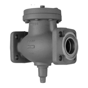
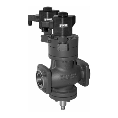
These piston-type, discharge gas powered, normally open,
heavy duty, semi-steel bodied valves are built with control
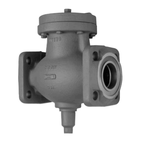
precision.The 32mm through 100mm (1-1/4" through 4", Fig.
1) port size valves are equipped with an attached modular
pilot solenoid, A2D pilot regulator, and manual lift stem. The
32mm (1-1/4") port size has a PTFE main seat; the 40mm
(1-5/8") port and larger have a metal to metal seat.
PURPOSE
The purpose of the CK-5 gas-powered suction stop valve is
to provide the normal operating features of the R/S CK-2 stop
valve. In addition, this unique control valve incorporates a
built-in mechanical fail-safe feature which prevents the
undesirable effects of an immediate opening of the valve in
the event of an electrical power failure while the evaporator is
in defrost.
Along with the standard R/S type CK-2 gas-powered suction
stop valve, the CK-5 is typically used for low temperature
applications in wet return lines in liquid recirculation systems
or on both liquid legs and gas return legs of flooded
evaporators. Due to its normally open construction, pressure
drop is minimal in suction or wet return applications. In
addition, on flooded evaporators normal gravity circulation is
unrestricted. For gravity flooded evaporators, both valves
should be installed with their flow arrows pointing towards the
surge drum.
PRINCIPLES OF OPERATION
For closing of the CK-5 valve, high pressure gas from an
external source is admitted through the pilot solenoid valve to
the top of the piston. The gas pressure acting on the piston
forces it down, compressing the opening spring, firmly seating
the valve’s seat bead.The valve will not close unless pressure
above the piston exceeds the downstream pressure by at least
5 psi (0.35 bar).
After the termination of the hot gas injection period, any style
of suction stop valve must reopen in order for refrigeration to
resume. For the CK-5 to open, the valve’s pilot solenoid
de-energizes, thereby interrupting the pilot stream flow of
discharge gas to the top of the valves piston. The main valve
will continue to remain closed, however, since residual
pressure in the coil is transmitted through passage N, through
the pilot regulator to the top of the piston. [Note: The pilot
regulatorshould beadjustedto maintain aminimalset point,
approximately 10 psi.] Under a standard defrost sequence
for most low temperature evaporators, a “bleed down” or vent
solenoid will energize to slowly equalize pressures between
the coil and the suction line. It is imperative to incorporate a
310229
Refrigerating Specialties Division 2
“bleed down” solenoid in a defrost group of control valves
which includes a CK-5 (See Fig. 5 and 6). Without this gradual
equalization period, which generally takes one to two minutes,
the CK-5 will stay closed for a prolonged period of time as the
coil pressure slowly equalizes in series through the pilot
regulator, then through the piston bleed hole.
The ability of the CK-5 to stay closed during an interruption of
power, while an evaporator is in the process of defrosting, is
its single greatest advantage.Where power failures can occur
with any frequency, consideration should be given to this
unique valve. By design, a standard CK-2, or a competitive
valve with a similar design, would open immediately as residual
coil pressure surges through the valve should power to the
pilot solenoid suddenly be interrupted during a defrost. The
design of the CK-5 prevents this from occurring and prevents
the dangerous consequences to the system under these
conditions.
In the event the CK-5 pilot solenoid de-energizes due to a
power failure while the evaporator is in defrost, the defrost
coil pressure (typically at or about 70 psig for ammonia) will
continue to be transmitted through passage “N”, through the
pilot regulator and to the top of the piston.This pilot pressure
acts as a “closing” force acting upon the larger effective area
of the top of the piston, and will overcome the “opening” force
of coil pressure working against the underside of the piston.
The valve will therefore remain closed due to the greater
closing force until the coil pressure is equalized through the
piston bleed hole.
The larger the evaporator, and the greater its internal volume,
the longer this venting or equalization period will require. By
utilizing a bleed down solenoid in the control group during
the standard defrost sequence, the CK-5 will return to its open
position immediately after the equalizing period which is
controlled by the time clock.
ADJUSTMENT
The pilot regulator should be adjusted to maintain a minimum
set point of about 10 psi. This represents approximately 1/2
turn clockwise of the adjusting stem starting with the stem
turned completely out.
MANUAL LIFT STEM
If it is desired to hold open the CK-5 manually, remove #34
Sealing Cap and turn #27 Seat Lifting Stem inward as far as
possible. The valve cannot close now until the #27 Seat Lift
Stem is once again turned out.
STANDARD COIL *
120 V 60 HZ OR 110 V 50 HZ 204843
240 V 60 HZ OR 220 V 50 HZ 204844
208 V 60 HZ 204845
240 V 50 HZ 204846
QUICK DISCONNECT COIL *
120 V 60 HZ OR 110 V 50 HZ 204859
204 V 60 HZ OR 220 V 50 HZ 204860
208 V 60 HZ 204861
240 V 50 HZ 204862
* Used on 1-1/4" (32mm) to 4" (100mm) Port Size Valves
CK5 1-1/4"TO 4"
PRESSURE BEARING COM PONENTS
COM PONENT DESCRIPTION M ATERIAL
BODY DUCTILE IRON GGG 40.3
BODY,A2D DN DUCTILE IRON GGG 40.3
BONNET,A4W DUCTILE IRON GGG 40.3
COVER,TOP DUCTILE IRON GGG 40.3
ADAPTER,1-1/4CK5 DN DUCTILE IRON GGG 40.3
INSTALLATION
Protect inside of valve from dirt and chips during installation.
The CK-5 Suction Stop Valve may be installed on its side or
vertically upright in either vertical or horizontal pipe lines.
Figure 5 illustrates the installation of the 32mm through 100mm
(1-1/4" through 4") port size valves in a horizontal pipe line.
Figure 6 illustrates the installation of the 125mm and 150mm
(5" and 6") port size CK-5 stop valves in a horizontal pipe line.
A bypass equalizing solenoid valve, a requirement with any
size CK-5, ‘is also shown. The remote discharge gas supply
solenoid used with the larger 5" and 6" valves, the R/S type
S8F, is a gravity closing valve and must be mounted in a
horizontal line with its manual opening stem in a vertical
position as shown.
Never install the valve with its pilot section directly beneath
the main valve.The direct mounted pilot solenoid on the 32mm
through 100mm (1-1/4" through 4") port size valves should be
maintained above the centerline on a horizontal pipe.
When used on a suction or wet return line, the arrow on the
valve should point in the direction of normal fluid flow. When
used on either gas or liquid legs of a flooded evaporator, the
arrow on the valve body should point from the evaporator to
the surge drum.
ELECTRICAL
The pilot solenoid used on the 32mm through 100mm (1-1/4"
through 4") port size CK-5 stop valves, type S6B, is unique to
the Refrigerating Specialties line of control valves. In addition,
the pilot light assembly used with the S6B, the R/S type PLT-5,
is unique to the product line.Like the R/S type PLT-2, the PLT-5
is designed to meet NEMA 4 (watertight) requirement for
outdoor use. However, unlike other pilot lights available from
R/S (types PLT-1 and PLT-2), the PLT-5 is wired directly to
line voltage. Please refer to R/S product bulletin 60-30 for
additional information regarding the PLT-5 pilot light assembly.
The Refrigerating Specialties Division’s molded, water
resistant, Class “H” solenoid coil is designed for long life and
powerful opening force. The standard coil housing meets
NEMA 3R and 4 requirements. This sealed construction can
withstand direct contact with moisture and ice. By definition,
Class “H” coil construction will permit coil temperatures, as
measured by resistance method, as high as 180°C. (356°F.)
Final coil temperatures are a function of both liquid and
ambient temperatures. The higher fluid temperatures require
lower ambient temperatures so the maximum coil temperature
is not exceeded. Conversely, low fluid temperatures permit
higher ambient temperatures.
A solenoid coil should never be energized except when
mounted on its corresponding solenoid tube.
The solenoid coil must be connected to an electrical line with
volts and Hertz the same as stamped on the coil The supply
circuits must be properly sized to give adequate voltage at
the coil leads even when other electrical equipment is
operating. The coil is designed to operate with line voltage
from 85% to 110% of rated coil voltage. Operating with a coil
voltage above or below these limits may result in coil burnout.
Also, operating with a coil voltage below the limit will definitely
result in lowering the valve’s maximum opening pressure
differential. Power consumption during normal operation will
be 18.2 watts or less,
3
Refrigerating Specialties Division
ITEM DESCRIPTION
1SealCap
2Gasket
3Nut,Packing
4 Packing
5 Washer
6 Stem, Adjusting
8 Bonnet
9 Name Plate
10 Screw
11 Bolt, Bonnet
12 Spring Rest, Upper
13 Spring, Range
14 Spring Rest, Lower
15 Diaphragm Follower
16 Gasket
17 Diaphragm
18 Pilot Seat
19 Gasket
20 Screw
21 Cover
22 Gasket
23 Adapter
24 Gasket
25 Piston
26 Spring
27 Stem, Manual Opening
28 Body
29 Screw
30 Washer
31 Packing
32 Nut, Packing
33 Gasket
34 Seal Cap
35 Cover, Bottom
37 Gasket
39 Disc Strainer Assembly
40 Tube
41 Plunger Asm
42 Seat
43 O-Ring
44 Body, Solenoid
46 Screw
48 Body, Pilot
49 Screw
50 O-Ring
For replacement parts and prices, consult
PARTS KITS LIST PRICE SCHEDULE
INDUSTRIAL AND FLO-CON (PK)
4
Parker Hannifin Corporation • Refrigerating Specialties Division
2445 South 25th Avenue • Broadview, IL 60155-3891 USA
Telephone: (708) 681-6300 • Fax (708) 681-6306
BOLTTORQUETABLE
ITEM PORTSIZE TORQUE
7/16" Flange Bolt 1/2" 28 ft lb
5/8" Flange Bolt 3/4"- 2" 85 ft lb
3/4" Flange Bolt 2-1/2" - 3" 105 ft lb
7/8" Flange Bolt 4" 150 ft lb
5/16"- 18 Bonnet Bolt 3/4" - 4" 15ft lb
5/16"-18 Adapter Bolt 3/4" - 2" 15ft lb
5/8"-11 Adapter Bolt 3" - 4" 75 ft lb
BottomCap 3/4" - 1-1/4" 150 ft lb
1/2"-13 Bottom Cap Bolt 1-5/8" - 2-1/2" 50 ft lb
5/8"-11 Bottom Cap Bolt 3" - 4" 75 ft lb
WARRANTY
All Refrigerating Specialties’ products are warranted against
defect in workmanship and materials for a period of one year
from date of shipment from the factory. Unless otherwise
approved in writing by Refrigerating Specialties this warranty
is in force only when products are properly installed,
maintained and operated for normal refrigeration application
as specifically stated in Refrigerating Specialties catalogs or
bulletins. Defective products, or parts thereof, returned to the
factory with transportation charges prepaid will be replaced
or repaired at Refrigerating Specialties’option, free of charge,
F.O.B. factory, as long as they are found to be defective by
factory inspection. Warranty does not cover products which
have been altered or repaired in the field, damaged in transit,
or which have suffered accidents, misuse, or abuse. Products
disabled by dirt, or other foreign substances will not be
considered defective.
THE EXPRESS WARRANTY SET FORTH ABOVE
CONSTITUTES THE ONLY WARRANTY APPLICABLE TO
REFRIGERATINGSPECIALTIESPRODUCTS,ANDIS INLIEU
OF ALL OTHER WARRANTIES, EXPRESS OR IMPLIED,
WRITTEN OR ORAL, INCLUDING ANY WARRANTY OF
MERCHANTABILITY, OR FITNESS FOR A PARTICULAR
PURPOSE. No employee agent, dealer or other person is
authorized to give any warranties on behalf of Refrigerating
Specialties, nor to assume, for Refrigerating Specialties, any
other liability in connection with any of its products.
SAFE OPERATION (See Bulletin RSBCV)
People doing any work on a refrigeration system must be
qualified and completely familiar with the system and the
valves involved, or all other precautions will be meaningless.
This includes reading and understanding pertinent product
bulletins and the current Bulletin RSBCV prior to installation
or servicing work.
CK5 DIMENSIONS
1-1/4" 1-5/8" 2" 2-1/2" 3" 4"
A 17.6 19.7 19.7 20.2 24.9 27
B
C 8 9.9 9.9 9.9 12.1 14.1
D 6.3 6.9 6.9 7.1 10.7 11.5
E 4.6 5.5 5.5 6.2 7 8.8
F 4.4 4.6 4.6 4.9 5.6 6.2
G 5.4 5.5 5.5 5.9 6.6 7.7
H 4.8 5.3 5.3 5.2 4.8 5.5

Other Parker Control Unit manuals

Parker CK-2W User manual

Parker

Parker CK-2W User manual

Parker PEV Service manual

Parker

Parker PEV Service manual

Parker PACHC Series User manual

Parker

Parker PACHC Series User manual

Parker DN80 User manual

Parker

Parker DN80 User manual

Parker PSUP Series User manual

Parker

Parker PSUP Series User manual

Parker PACHC Series User manual

Parker

Parker PACHC Series User manual

Parker BAM20 User manual

Parker

Parker BAM20 User manual

Parker 2B4 Series User manual

Parker

Parker 2B4 Series User manual

Parker D1FV EE Series User manual

Parker

Parker D1FV EE Series User manual

Parker D Series User manual

Parker

Parker D Series User manual

Parker PSSN8M8A Installation and maintenance instructions

Parker

Parker PSSN8M8A Installation and maintenance instructions

Parker TFP Series User manual

Parker

Parker TFP Series User manual

Parker PSSTR4M12A Installation and maintenance instructions

Parker

Parker PSSTR4M12A Installation and maintenance instructions

Parker P33 Quick setup guide

Parker

Parker P33 Quick setup guide

Parker Series DFplus User manual

Parker

Parker Series DFplus User manual

Parker PQDXXA-Z10 Installation and operation manual

Parker

Parker PQDXXA-Z10 Installation and operation manual

Parker SciLog DINCon Assembly instructions

Parker

Parker SciLog DINCon Assembly instructions

Parker PSST8M23A Installation and maintenance instructions

Parker

Parker PSST8M23A Installation and maintenance instructions

Parker LINKnet TechBox Series User manual

Parker

Parker LINKnet TechBox Series User manual

Parker CEV-S User manual

Parker

Parker CEV-S User manual

Parker PID00A-40X Series User manual

Parker

Parker PID00A-40X Series User manual

Parker S7A Service manual

Parker

Parker S7A Service manual

Parker VA01 Series User manual

Parker

Parker VA01 Series User manual

Parker PK2 User manual

Parker

Parker PK2 User manual

Popular Control Unit manuals by other brands

Pepperl+Fuchs VAA-2E-KE1-S Original instructions

Pepperl+Fuchs

Pepperl+Fuchs VAA-2E-KE1-S Original instructions

Kobelt 2544 Owner's Operation, Installation & Maintenance Manual

Kobelt

Kobelt 2544 Owner's Operation, Installation & Maintenance Manual

Ebyte E104-BT11 user manual

Ebyte

Ebyte E104-BT11 user manual

Honeywell REDLINK ERM5220R Product data

Honeywell

Honeywell REDLINK ERM5220R Product data

Duali DE-ABCM6 user manual

Duali

Duali DE-ABCM6 user manual

ENSIM SENSORS ELV Series operating manual

ENSIM SENSORS

ENSIM SENSORS ELV Series operating manual

Controlli VSBT quick start guide

Controlli

Controlli VSBT quick start guide

KEBCO F5 COMBICOM ModBus instruction manual

KEBCO

KEBCO F5 COMBICOM ModBus instruction manual

Raita BioModule Manual Installation

Raita

Raita BioModule Manual Installation

Siemens RUGGEDCOM RS900 installation guide

Siemens

Siemens RUGGEDCOM RS900 installation guide

DEHAS DEMAND VALVE QualityFlow operating instructions

DEHAS

DEHAS DEMAND VALVE QualityFlow operating instructions

Leadshine DM542 user manual

Leadshine

Leadshine DM542 user manual

Belden Lumberg Automation LioN-P 0980 ESL... manual

Belden

Belden Lumberg Automation LioN-P 0980 ESL... manual

SMART Embedded Computing RTM-ATCA-F140 Series Installation & use

SMART Embedded Computing

SMART Embedded Computing RTM-ATCA-F140 Series Installation & use

GEM R488 Victoria operating instructions

GEM

GEM R488 Victoria operating instructions

EL.MO. Spa SCMAS5 Technical manual

EL.MO. Spa

EL.MO. Spa SCMAS5 Technical manual

Texas Instruments TPS5430 user guide

Texas Instruments

Texas Instruments TPS5430 user guide

Siemens FDCI221 Installation

Siemens

Siemens FDCI221 Installation

manuals.online logo
manuals.online logoBrands
  • About & Mission
  • Contact us
  • Privacy Policy
  • Terms and Conditions

Copyright 2025 Manuals.Online. All Rights Reserved.