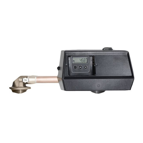
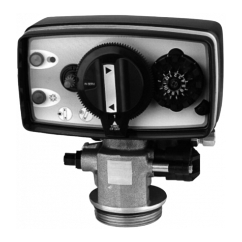
Fleck 7700 User manual

7700 VALVE
table of CONTENTS:
1 VALVE SPECIFICATION P. 2
2 VALVE INSTALLATION P. 3
3 INSTALLATION INSTRUCTIONS P. 4
4 VALVE OPERATION P. 5
5 TROUBLESHOOTING P. 7
8P Vanne 7700 ANG 8/03/05 19:20 Page 1

1 - VALVE SPECIFICATION
7700 VALVE
2
Installation N°
Valve serial N°
Tank size
Resin type
Resin volume
Time clock
Meter delayed
Meter immediate
System capacity m3°tH
Inlet water hardness °tH
Water hardness after mixing valve
°tH
Brine tank size L
Quantity of salt per regeneration Kg
VALVE TECHNICAL CHARACTERISTICS
REGENERATION CYCLE SETTINGS
INITIATION
Days/ litres
2 A.M.
or
REGENERATION REGLEE
REGENERATION TIME
Cycle 1 (Fltr) (dF) (dFFF) Min.
HYDRAULIC SETTINGS
VOLTAGE
Injector size
Cycle 2 (Fltr) (dF) (dFFF) Min.
Cycle 3 (dF) (dFFF) Min.
Cycle 4 (df) (dFFF) Min.
Drain line flow control (DLFC) GPM
Brine line flow control (BLFC) GPM
NOTES
Cycle 5 (df) (dFFF) Min.
Cycle 6 (dFFF) Min.
24V/50Hz
24V/60Hz without transformer
8P Vanne 7700 ANG 8/03/05 19:37 Page 2

2 - VALVE INSTALLATION
37700 VALVE
Water pressure
A minimum of 1,4 bar of water pressure is required for the regeneration valve to operate effectively.
Do not exceed 8,5 bar ; if you face this case, you should install a pressure regulator upstream the system.
Electrical connection
An uninterrupted current supply is required. Please make sure that your voltage supply is compatible with your
unitbeforeinstallation.Iftheelectricalcableisdamaged,itmustimperativelybereplacedbyaqualifiedpersonal.
Existing plumbing
Existing plumbing should be in a good shape and free from limescale.
The installation of a pre filter is always advised.
By-pass
Always provide a by pass valve for the installation, if the unit is not equipped with one.
Water temperature
Water temperature is not to exceed 43°C, and the unit cannot be subjected to freezing conditions.
Presentation
2.1
2.2
2.3
2.4
2.5
2.6
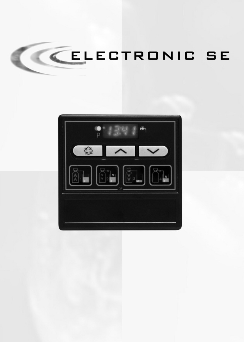
Service indicator:
- Valve in service : L.E.D on
- Night regeneration:
flashing L.E.D.
Flow indicator:
L.E.D. flashes proportionally
to flow.
Programmation indicator:
- valve in programmation :
L.E.D on. Not used
in metrical mode.
Regeneration button Value setting buttons.
8P Vanne 7700 ANG 8/03/05 19:33 Page 3

Install the unit in a chosen place on a flat firm surface.
During cold weather, it is recommended to bring the valve back to room temperature before operating.
All plumbing for water inlet, distribution and drain lines should be done correctly in accordance with legislation in
force at the time of installation.
The distribution tube should be cut flush with the top of the tank. Slightly bevel the ridge in order to avoid
deterioration of the seal whilst fitting the valve (View sketch below).
Lubricate the distribution tube joint and the joint with a 100% Silicon lubricant. Never use other types of greases
that may damage the valve.
All soldering on main plumbing and to the drain line should be done before fitting the valve. Failing to do so can
generate irreversible damages.
Use Teflon® tape if necessary in order to seal between the drain fitting and the outlet flow control.
On units with by-pass, place in by-pass position. Turn on the main water supply. Open a cold soft water tap nearby
and let run a few minutes or until the system is free from foreign material (usually solder) that may have resulted
from the installation. Once clean, close the water tap.
Place the by-pass in service position and let water flow into the mineral tank. When water flow stops, slowly open
a cold water tap nearby and let run until the air is purged from the unit.
Plug the valve to a power source. Once plugged the valve may do a cycle on its own in order to go to service
position.
Fillapproximately25mmofwaterabovethegridplate,(ifused).Otherwise,filltothetopoftheaircheckinthebrine
tank. Do not add salt to the brine tank at this time.
Initiate a manual regeneration, bring the valve into « brine draw and slow rinse position » in order to draw water
from the until the blockage of the anti air valve ; the water level will be approximatively in the middle of the air
check.
Open a cold water tap and let the water run in order to drain the air out of the circuit.
Bring the valve in brine refill position and let it get back to service position automatically.
Now you can add salt to the brine tank, the valve will operate automatically.
3 - INSTALLATION INSTRUCTIONS
47700 VALVE
3.1
3.2
3.3
3.4
3.5
3.6
3.7
3.8
3.9
3.10
3.11
3.12
3.13
3.14
3.15
Distribution tube length cut
Bevel exterior
diameter
Cut at bottle height
Lubricate O’ ring Distribution tube
Tube adapter dia.32
to 1.05” (27mm)
8P Vanne 7700 ANG 8/03/05 19:21 Page 4

4 - VALVE OPERATION
5
Timeclock regeneration
The number of days between each regeneration cycle is preset. Once reached, regeneration is triggered at the
programmed time.
Metered regeneration
The valve calculates the amount of water it can soften between 2 regenerations based on the exchange capacity
(m3°tH) and inlet water hardness that are preset.
Immediate or meter delayed regeneration valves
As softened water is used, the remaining volume display will decrease until reaching its reserve capacity (meter
delayed regeneration) or until zero (immediate metered regeneration). When this happens, regeneration is
automatically triggered either straight away or at a preset time.
Service
Service display
Inoperation,thetimeofthedayandthevolumeremainingwill alternatively be displayed (except for the time clock
version: only the time of day will be viewed).
Time of day Remaining Volume: 765 1
4.1
4.1.1
4.2
4.2.1
4.1.2
7700 VALVE
If the remaining volume is higher than 9999 litres, the letter « t » will appear
to indicate that the indicated number must be multiplied by 1000.
I.E. t 15 = 15 *1000 = 15 000 litres capacity.
In delayed metered regeneration, this display indicates that the remaining
capacity is exhausted. The service position L.E.D will flash and a
regeneration cycle will start at the programmed time.
Time of day setting
Set the time of day minute by minute by pressing the or button. Press and hold the button to set quickly
the time of day.
Regeneration
Regeneration displays
During the regeneration cycle, the valve will show the current cycle number the valve is advancing to (flashing
display) or has reached as well as the time remaining in that cycle (fixed display). Once all the regeneration cycle
steps have been completed the valve will return to the service position.
For example:
The valve is advancing to its 2nd cycle.
The number 2 and the L.E.D. are flashing. The valve is in its 2nd cycle;
there are 65 minutes left.
8P Vanne 7700 ANG 8/03/05 19:21 Page 5

Start a manual regeneration
There are 2 options to initiate regeneration.
A) Press and release the button.
If an immediate regeneration is programmed, the valve will immediately start regeneration.
With a delayed regeneration, the service L.E.D. will begin to flash immediately and the regeneration will occur at
the preset regeneration time.
B) Press and hold for 5 seconds the button.
In any case the valve will go into regeneration immediately.
Advance to the next regeneration cycle
To advance to the next regeneration cycle, press the button.
This will have no effect if the valve is already advancing to the next cycle.
PROGRAMMING
CAUTION: The programming has to be done only by the installer for the setting of the valve parameters. The
modification of one of these parameters could prevent the good functioning of the device.
To enter the program mode, the valve has to be in service. While in program mode, the valve will continue to
operate normally monitoring all information. The programming is stored in permanent memory with or without line
or battery backup power.
To enter programming mode, press simultaneously the and for 5 seconds.
Press on the button in order to jump to the next stage.
Use the and buttons in order to modify the displayed values.
Note: You must pass through all the programming steps and come back in service position to save the
modifications that have been done during the programming mode.
4 - VALVE OPERATION
7700 VALVE
6
4.3
4.2.2
4.2.3
4.4
Water hardness °tH
For example: 25 °tH
(Not viewed in time clock version)
Regeneration time
For example: 2 A.M.
(only visualised in delayed metered and timeclock mode)
Day override (maximum days between 2 regenerations)
For Example : regeneration every 4 days
(only visualised in timeclock mode, setting is imperative.)
VALVE OPERATION DURING A POWER FAILURE
During a power failure, all the data will be saved and restored once the line power is restored. The data can be
saved for many years with no loss. The electronics will be inoperative and all regeneration will be delayed. The
electronicswill restorealltheinformationto thetimewherethepower failureoccurred.The valvedoesnotrecord
the amount of water used during a power cut.
If the valve is in delayed metered regeneration, the reserve capacity will be set to a third of the full capacity.
8P Vanne 7700 ANG 8/03/05 19:21 Page 6

5 - TROUBLESHOOTING
77700 VALVE
PROBLEM CAUSE CORRECTION
1. Softener fails A. Electrical service to unit has been interrupted. A. Assure permanent electrical service
to regenerate (check fuse, pull chain or switch).
B. Timer is not operating properly B. Replace the timer.
C. Meter cable disconnected. C. Check the meter connection to the
timer and the meter cover.
D. Jammed meter. D.Clean or replace the meter.
E. Defective valve drive motor. E. Replace the drive motor.
F. Improper programming. F. Check the programming
and reset as needed.
2. Softener delivers A. By-pass is opened. A. Close the by-pass valve.
hard water
B. No salt in the brine tank. B. Add salt to the brine tank and
maintain the salt level above
the water level.
C. Injector or screen is blocked C. Replace or clean the injector
and screen.
D. Insufficient water into the brine tank D. Check the brine tank fill time and clean
the brine flow control if it’s blocked.
E. Hardness from the hot water tank. E. Repeated flushing of the hot water
tank is required.
F. Leak at the distributor tube. F. Make sure the distributor tube is not cracked.
Check the O’ ring and tube pilot.
G. Internal valve leak. G. Replace seals and spacers
and/or piston.
H. Flow meter jammed. H. Remove the obstruction from meter.
I. Flow meter disconnected. I. Check the meter connection
to the timer and the meter cap.
J. Improper programming. J. Check the programming
and reset as needed.
3. Unit uses too much salt A.Improper brine refill setting A. Check salt usage and salt setting.
B. Excessive water in the brine tank. B. See problem n°7.
C. Improper programming. C. Check the programming
and reset as needed.
4. Loss of water pressure A. Iron build up in line to softener. A. Clean the line to the softener.
B. Iron build up in the softener. B. Clean the valve and resin bed.
C. Inlet of the valve plugged due C. Remove the piston and clean
to foreign material. the valve.
5. Loss of resin through A. Top distributor missing or broken. A. Add or replace the top distributor.
drain line
B. Air in water system. B. Ensure the presence of air check
system in the brine tank.
C. Drain line flow control C. Ensure the drain line flow control
is the wrong size. is sized correctly.
8P Vanne 7700 ANG 8/03/05 19:21 Page 7

Reproduction interdite01/05 - P/N 27286 GB
PROBLEM CAUSE CORRECTION
6. Iron in softened water. A. Fouled resin bed. A. Check backwash, brine draw and
brine tank refill ; increase frequency
of regeneration; increase backwash time
B. Iron exceeds the recommended B. Contact the dealer.
parameters.
7. Excessive water A. Plugged drain line flow control. A. Clean the drain line flow control (DLFC).
in brine tank
B. Brine valve failure. B. Replace the brine valve.
C. Improper programming C. Check the programming
and reset as needed.
8. Salted water A. Blocked injector or screen. A. Clean injector and replace screen.
in service line
B. Timer not operating correctly. B.Replace timer.
C. Foreign material in brine valve. C. Clean or replace brine valve.
D. Foreign material in brine D. Clean brine line flow control.
line flow control (BLFC).
E. Low water pressure. E. Raise water pressure to 1,4 bar
at least.
F. Improper programming. F. Check the programming and
reset as needed.
9. Softener fails A. Plugged drain line flow control. A. Clean drain line flow control (DLFC).
to draw brine
B. Plugged injector. B. Clean injector and replace screen.
C. Injector filter blocked. C. Clean filter.
D. Low water pressure. D. Increase water pressure to 1,4 bar
at least.
E. Internal valve leak. E. Change seals and spacers
and/or piston assembly.
F. Improper programming. F. Check the programming
and reset as needed.
G. Timer not operating properly G. Replace timer.
10. The valve cycles A. Timer not operating properly. A. Replace timer.
continously
B. Faulty optical sensor. B. Replace the circuit board.
C. Faulty cycle cam operation. C. Replace cycle cam or reinstall.
11. Drain flows A. Foreign material in the valve. A. Remove piston assembly and inspect bore,
continuously remove foreign material and check
the valve in various regeneration positions.
B. Internal valve leak. B. Replace seals spacers
and or piston assembly.
C. Valve jammed in brine C. Replace piston assembly
or backwash position. and seals and spacers.
D. Timer motor stopped or jammed D. Replace timer motor and check
all gears for missing teeth.
E. Timer not operating properly. E. Replace timer.
5 - TROUBLESHOOTING
87700 VALVE
8P Vanne 7700 ANG 8/03/05 19:22 Page 8

7700 VALVE PROGRAMMING
12:01
U--2
1. Press once the button
to go from one display mode
to another.
2.
Set parameters values by
using the and buttons.
3. Depending on the
programmation, some
displays will not appear and
some will not be variable.
4. Bold characters default
setting.
7700 VALVE
Set the clock on 12:01 Press simultaneously on the and
buttons for 5 seconds.
1. Display unit (U)
I.e.: - Gallon [U--1]
- Litre [U--2]
dF 2. Regeneration way
I.e.: - downflow [dF]
- downflow brine fill first [dFFF]
- Filter [Fltr]
7--3 3. Regeneration type (7)
I.e.: - Time clock regeneration [7--1]
- Metered immediate regeneration [7--2]
- meter delayed regeneration [7--3]
C180 4. system capacity
I.e.: - Us format in Kilo grain [C-24]
- metrical format m3x°tH [C180]
1°tH=10ppm of CaCO3
H-15 5. Input water hardness (H)
I.e.: - Us Format in grain) [H-15]
- metrical format (french degrees) [H-25]
2:00 6. Regeneration time
I.e.: - regeneration at 2 A.M. [2:00]
A--7 7. Regeneration day override
I.e.: - Regeneration every 7 days [A--7]
- No overriding [AOFF]
A
Rev.1
R°PROGRAMMATION ANG 8/03/05 19:18 Page 1

LEVEL DESCRIPTION
Enter master programmation mode
Set time date on to 12:01 and press simultaneously on the and for 5 seconds.
A L.E.D. will display to show that the valve is in programmation mode. Each programmation step can be modified.
- Use the and in order to adjust setting values.
- Press the button to advance to the next programmation stage.
Display unit
Notice: if this setting has just been changed, the valve will go around fully and come back to service mode.
Default setting: [U--1]
This setting is identified by the letter U. There are two types:
- [U - - 1] US type: the measure unit is in gallons, time display is 2x12 hours, hardness in grain.
- [U - - 2] metric type: the measure unit is litre, time display is 24 hours, hardness in m3x°Th.
Regenerating way
Notice: if this setting has just been changed, the valve will go around fully and come back to service mode.
Default setting : [dF]
This display is used in order to tell the card the piston type used on the valve.
- dF : down flow
- dFFF : down flow with brine fill first
- Fltr : Filter
Regeneration type
Default setting : [7--3]
This setting is identified by the number 7. This function allows the setting of the valve regeneration type. There are 3 possibilities:
- Time clock: The electronics establish that a regeneration is requested when the number of days between two regenerations
has been reached; the new cycle beginning at the preset time. The setting of the day override establishes the number of days
between two regenerations. [7--1]
- Metered immediate regeneration: The electronics establish that a regeneration is required when the softened water volume
has reached zero. The regeneration starts immediately. [7--2]
- Meter delayed regeneration: The electronics establish that a regeneration is requested when the volume of softened water
used has reached the reserve capacity of the unit. Regeneration will begin at a preset time; the system will automatically
establish a reserve capacity. [7--3]
System capacity
Not visualized in time clock mode: [7--1]
This setting is identified by the letter C. It contains an extended mode Ct, the letter t meaning a multiplication by 1000.
It enables the regulation of the system capacity in m3x tH°.
The system calculates the water volume that needs to be treated before a regeneration request.
In meter delayed mode, the system will establish a reserve capacity.
I.e. : 35 m3°tH [C-35]
Feed water hardness (H)
Not visualized in time clock mode: [7--1).
Default setting: [H-15]
This setting is identified by the letter H. It enables the regulation of the feed water hardness.
The system uses this setting and the previous one to establish softened water capacity.
I.e. : 25 °tH [H-25]
Regeneration time
Not visualized in immediate metered mode: [7--2]
It allows setting of the regeneration time. The two dots between hour and minute display do not flash in order to differentiate
with the current time display.
I.e. : regeneration at 2 :00 A.M. [2:00]
Day override
This setting is identified by the letter A. It allows to set the maximum amount of days that the system can stay in service mode
without a regeneration. This stage is compulsory for a valve in time clock mode and optional for a valve in metered mode.
I.e. regeneration every 7 days [A--7]
- Cancelled stage [AOFF]
7700 VALVE
B
1.
2.
3.
4.
5.
6.
7.
V°PROGRAMMATION ANG 8/03/05 19:16 Page 1

7700 VALVE PROGRAMMING
1-10
7700 VALVE
8. Cycle times based on dF
8.1. Backwash:
I.e.: 10 minutes [1-10]
2-60 8.2. Brine draw & slow rinse
l.e.: 60 minutes [2-60]
3--5 8.3. Second backwash
l.e.: 5 minutes [3--5]
4-10 8.4. Fast rinse
I.e.: 10 minutes [4-10]
5--12 8.5. Brine fill
I.e.: 12 minutes [5-12]
F21.6 9. Flow meter size (F)
I.e.: - 1-1/4’’ turbine meter (US) [F-78]
- 1-1/4’’ turbine meter (metrical) [F21.6]
cF25 10. Security coefficient (cF)
I.e.: - security coefficient 25% [cF25]
- no security coefficient [cF-0]
LF50 11. Electrical mains frequency
I.e.: - frequency 60 Hz [LF60]
- frequency 50 Hz [LF50]
Press once on button to save modified parameters
and return in service mode.
Note: Valve calculates programming changes [CALC]
and return to the service mode/Time of day.
C
Rev.1
1. Press once the button
to go from one display mode
to another.
2.
Set parameters values by
using the and buttons.
3. Depending on the
programmation, some
displays will not appear and
some will not be variable.
4. Bold characters default
setting.
R°PROGRAMMATION ANG 8/03/05 19:18 Page 2

LEVEL DESCRIPTION
Regeneration cycles
The settings 8-1 to 8-6 enable the regulation of the regeneration cycle times.
The amount of cycles is established by the piston type. (View stage 2).
I.e.:
Cycle 1-8 mn [1--8]
Cycle 2-65 mn [2-65]
Cycle 3-4 mn [3--4]
DF dFFF FLtr
1) Backwash 1) Brine refill 1) Backwash
2) Brine draw/Slow rinse 2) Pause (salt saturation) 2) Fast rinse
3) 2nd backwash 3) Backwash
4) Fast rinse 4) Brine draw/Slow rinse
5) Brine refill 5) 2nd backwash
6) Fast rinse
Meter size
Not visualized in time clock mode: [7--1]
This setting is identified by the letter F. It allows to regulate the amount of pulses generated by the meter per litre.
The meter used with this valve is a 1-1/4’’ [F21.6]
Security factor
Not visualized in time clock mode: [7--1]
This setting is identified by the letters cF. It allows a security margin by lowering the available capacity.
The setting is a percentage.
I.e. :
- No security factor [cF 0]
- Security factor 35%: the available capacity is reduced by 35% [cF35]
Mains frequency
This setting is identified by the letters LF. It allows regulating the mains frequency.
If the frequency is set correctly, the timer display will remain accurate.
- 60 Hz (default setting with the following display U- - 1) [LF60]
- 50 Hz (default setting with the following display U- - 2) [LF50]
Notice:
If the regeneration way setting changes during the programmation, the valve will go round fully in order to reinitialize.
If the system capacity, hardness or security factor settings have just been modified during the programmation, the card will
recalculate the system capacity and take one third of the total capacity as a new value for the reserve capacity.
Error display
The codes only appear in service mode.
There are 3 possibles errors:
Error code
Err0
Err1
Err2
Cause
The motor is blocked
The motor runs continuously
The valve hasn’t regenerated for 99 days.
Remedy
Unplug the unit from the mains,
Once plugged back, the error code
disappears.
If the error cause isn’t solved, the code will
reappear. Do not attempt to solve the
problem. Change the card or motor.
A regeneration has to be done for the valve
to run normally.
Reset
Press simultaneously the buttons and for 25 seconds or until the day time displayed is 12 :00. The program will then take
its default settings.
The valve will have to be fully reprogrammed following the indications in the previous chapters.
Notice: if a reset has occurred, the valve will turn round fully to recover its initial position.
7700 VALVE
D
8.
9.
10.
11.
V°PROGRAMMATION ANG 8/03/05 19:30 Page 2
Other manuals for 7700
1
Other Fleck Control Unit manuals
Popular Control Unit manuals by other brands
Zodiac
Zodiac TRi pH Module Instructions for installation and use

HouseMate
HouseMate HouseMatePro Mk4 Pairing Instructions
Aprimatic
Aprimatic CF10/2 Technical instructions

Honeywell
Honeywell Notifier NZM-100-6 Installation and maintenance instructions
Toto
Toto TSMV Installation and owner's manual
Valve Concepts
Valve Concepts 5400 Installation, operation and maintenance manual
