BLMA Models Cantilever Signal Bridge User manual

Thankyouforpurchasingthisfine-scalemodel! Thisbridgehasbeendesignedforeasy
assembly,exceptionaldurability,andeaseofmounting. Pleasefeelfreetocontactusifyouhave
anycommentsorconcerns.Shouldanissuearise,sparepartsareavailableforpurchase.
!
!
!
!
!
!
Glue: Any medium CA (super) glue. (Super glue accelerator might also come in handy.)
Hobby Knife: A sharp hobby knife is imperative for cutting etched metal pieces from the
frame in which they come. (Be careful with sharp blades; use eye protection while cutting!)
File: To remove any burs left behind when the parts are cut from their etched frame.
Paint: Any flat black paint. We recommend using an air brush to apply the paint. It is easy to
cover the small details with paint applied by brush. Silver & White paint are needed as well.
Toothless Pliers: To aid in bending things such as the ladder supports, signal heads, etc.
*Toothless pliers decrease the risk of causing damage to delicate, etched-metal parts.
Toothpicks: Come in handy when applying glue or small dabs of “touch-up” paint.
Materials/Tools NeededMaterials/Tools Needed
Cantilever Signal Bridge InstructionsCantilever Signal Bridge InstructionsCantilever Signal Bridge Instructions
Please read through all instructions before assembling and painting this structure.
Modeled after a common Santa Fe protoype, this
Cantilever Signal Bridge has been in use all over the
countryforwelloverahalf century. Sturdyconstruction
and a solid design has allowed these bridges to last into
the new millennium. The photos to the right are of the
prototype bridge this kit is modeled after. Replaced on
the 1st of August, 2006, this relic survived long enough
toseeBNSFcometopoweroverSantaFerails.
THE PROTOTYPETHE PROTOTYPE
#4020#4020
THE MODELTHE MODEL
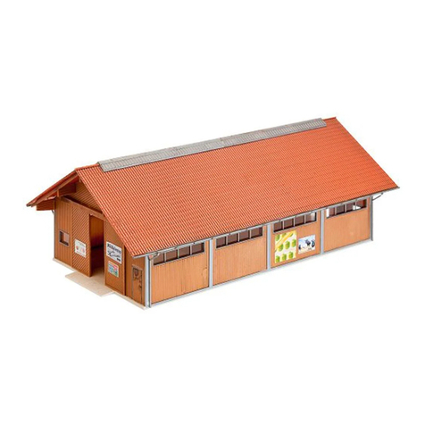
Our HO Scale model of this interesting bridge is an
exact scale replica of the prototype. If you look closely,
you will notice that everything down to the rivet detail is
in place! Because a solid model starts with solid
dimensions and drawings, all of the information used
was taken directly from the prototype. The model
photos to the right were taken at the same angle as the
prototypephotostoshowhowexactthismodelis.
BLMA Models
16623 Pear Blossom Ct.
Whittier, California 90603
Phone: 562-712-7085
#4020 - Signal Bridge Instructions

A. Main Span & Center Base
B. Vertical Posts & Ladder
C. Base
D. Top Handrail
E. Electrical Box (not pictured)
F. Signal Heads (3) (Non-operating - not pictured)
1. Base Assembly
Thebase of theprototypeis an angledconcrete block. LocatepartC and remove
it from it’s etched frame. Notice the half-etched fold lines on the underside of the
etching. Fold all sides so the half-etched lines are facing down. Note: Adding CA glue
fromtheinsidewillhelptopreventthesidesfrompushingoutward.
Please contact us at BLMAmodels.com for any spare part requests.
A B
DC
Bend sides down as shown. Completely assembled and
glued from the inside.
2. Vertical Post Construction
The main vertical post of this model is constructed of four separate
components. Through testing the product, we found this to be the best we to
faithfully recreate the construction methods of the bridge.
Locate and remove the four long posts from etching B. It is extremely
important that these posts remain perfectly flat. Notice that the ends of these four
pieces have short “tabs” protruding from them. These tabs will fit neatly into the
base assembly as well as the top handrail section (more on that later). Furthermore,
notice that the tabs on one end are longer than on the other end. The end with the
longest tabs will fit into the base. Continued on page 3...
AssemblyAssembly
PartsListPartsList
#4020 - Signal Bridge Instructions Page 2

3. Top Base Assembly
Startingwiththetwo solidposts, locatethe endwiththe longtab,dipitin CAand insert
it into the base. Of the entire kit, this is the most crucial part! Make sure that your post is
perfectlyvertical. The post must be completely vertical forthemodel to assemble correctly in
the later steps. The post can lean in toward the center a tad (so the top of it falls directly
above the center hole in the base). Repeat the steps above for the opposite post. Make sure
both posts are perfectly vertical (however, it’s OK for them to lean in toward the center and
ontoeachotheraswehavepicturedFigureB).
Fromthere, locate the other two verticalsupports and glue them into the base with the
long tab end first. These posts might have a tendency to lean out which is perfectly OK (we’ll
adjust them later.). By now, all of your posts should be glued in place and should be the same
height(FigureC). Throughoutthisprocess,makesurethatallpostsstaycompletelyvertical.
Figure A
Perfectly vertical post.
Figure B Figure C
Both solid posts in place. All four posts in place.
Locate and remove the Top Base from etching A. Note that there are half-etched
foldlinesonit’sbottomside. Foldtheendsdownatthehalf-etchedlines.
Locate your Base/Post assembly from step 2 along with your Top Base from the
stepabove;proceedwithsteponeandthentwobelow.
You will need to separate the
four vertical posts in order to easily
mount the Top Base in place.
Simply use your fingers or tweezers
to gently pull the four posts away
from the center. Continue gently
pulling the posts outward until the
space between them is slightly
largerthenthespaceatthebottom.
Step 1. Step 2. Add a dab of glue to the the
tops of the four posts. Carefully,
place the Top Base onto the
assembly so that the longest
side hangs over the only vertical
side of the Base. It is easiest to
insert the double pronged posts
into the bottom of the base and
then bring the single pronged
sidepiecesinward.
The longest end
of the Top Base
extends over
the only vertical
side of the Base.
Note the ends are folded down perpendicular to the center.
#4020 - Signal Bridge Instructions Page 3

4. Top Handrail Assembly
TheTopHandrailportion of this kitisetched in .010”
Stainless Steel for improved handrail durability over the
alternative (brass). Locate part D and remove it from it’s
etched frame. (Be careful whencutting the tie-barsfor the
handrailsasyoudonotwanttobentordistortthem.)
Bend all of the handrails perpendicular to the base.
Notice that the ends also have additional bend lines where
the handrails cross the width of the bridge (at the ends).
You may want to add a small dab of CA to the handrails
wheretheymeetinordertoensurebetterdurability.
Main structure assembly and completely
assembled Top Handrail etching.
Partially formed Top
Handrail etching.
The next step of the kit is gluing the Top Handrail section onto your main
structure. WiththeTopHandrailetchingand yourmainstructureassemblyin hand,test
fittheTopHandrailtoseehowitfitsintothetabsoftheVerticalPosts.
To mount, lay the Top Handrail section upside down so it is supported by the
handrails (do not apply excess pressure or you will crush the handrails!). Next, add a
line of CA down the center of the Top Handrail underside. Place the main structure
(being held upside down) onto the Top Handrail piece so that all of the tab holes align.
During this process, apply pressure to the Top Base so it lays flush with the underside of
theTopHandrail.
The Vertical Posts and Top Handrail should form a perfectly right angle. Adjust any
slight imperfection in the angle by gently pushing the pieces in the proper direction.
The Vertical Posts and horizontal walkway
(Top Handrail piece) should form a right angle.
5. Main Span Assembly
The next step in this kit is to add the Main Span pieces. Locate the two pieces
frometchingAandhavethemreadytogowithyourassembledmainstructure.
Lay the main assembled structure on it’s side. Test fit one of the Main Span
etchings to visualize how thingswill line up. Run a line of gluedown the edge of the Top
BaseontheundersideoftheTopHandrail. Continuedonpage5...
#4020 - Signal Bridge Instructions Page 4

Complete the previous steps for the opposite side of the structure.
Addadditionaldabsofgluefromtheinsidetoensuredurability.
6. Ladder Assembly
Locate the ladder from etching D. As with the other parts, be careful when
cutting the part from the etching as you do not want to distort/bend it. Note that the
tabs extending from the ladder that allow it to mount onto the vertical posts should NOT
beperpendiculartothebridge(theyareataslightangleforareason).
Locate the half-etched fold lines on the tabs extending from the bridge and bend
themtoformaright anglewith thebridge. Iftheladderisperfectlyverticalinyourhand
andyou’reviewing itfromtheside, thetabs shouldangleup slightly. When theladder is
mounted on to the bridge, the tabs will then become perfectly horizontal while the
ladderwilltaperclosertotheverticalpostsasitrisesupthestructure.
Run a line of glue along
dotted line (see arrow). Repeat the same steps to
complete the opposite side.
Fold mounting tabs perpendicular
to the ladder. These should NOT
be perfectly perpendicular
to the ladder.
Add a dab of glue to the ends of
each tab and place on model so
the top, curled over handrails
are just above the walkway.
Make sure the ladder is firmly
glued in place. Bend the two
curled runner tops inward
as shown above.
We’ve included a typical Electrical Box to
compliment the Signal Bridge. To assemble,
simply clean up the castings, glue the doors in
place (line up the hinges for best results), and
affix the cast footings. Like the other cast metal
parts in this kit, the Electrical Box is
manufacturedinconjunctionwithDetailsWest.
ElectricalBoxElectricalBox
#4020 - Signal Bridge Instructions Page 5

The Signal Heads provided in this kit are exact scale
replicasofthecommon, “Searchlight”signal(namedafterit’s
appearance). Although our signal heads are non-operating,
after-marketLED’smaybeinstalledifdesired.
Note: Wehavesuppliedyouwithanextrasignalhead.
Locate parts A and C. Part C
should fit through the center of
part A. Remove burs from part
C if necessary.
AE
D
B
C
A. Etched Target and Hood
B. Signal Head Body
C. Signal Head Insert
D. Signal Head Mount
E. Mounting Rod
1. 2. 3.
Bend the hood around the
provided brass pole to give
it the proper curvature.
It is imperative that the hood be
shaped to the proper curvature so it
will mount correctly onto the
assemblyfromstep2.
Insert the mounting pegs on the
hood through the corresponding
holes on the target. The hood
shouldwrapneatlyaroundpartC.
Once fully inserted, bend the
mounting tabs on the hood toward
theoutsideofthetarget.
6.
5.
4.
7. 8. 9.
12.11.10.
Gluetheassemblyfromstep6into
part B (part C’s narrow end should fit
into the large opening on part B).
Affixwithglue.
Locate part D and bend its sides
perpendicular to the middle portion.
We suggest bending with toothless
pliersasshown.
Once both sides are folded down,
bend the tiny nub at the end of the
part the opposite direction of the
sides.
The small nub bent in figure 9 fits
into the bottom of the signal head
(partB).
Cut down part E so it is the height
of the handrail & glue in place. The
best way to cut brass tube is by
rollingit underasharphobbyknife.
Glue the completed signal head
assembly onto the pole. Vertical
position and the number of signals
dependsontheprototypemodeled.
Our Signal Heads are also sold seperately in a three pack. BLMA #4000
Add a small amount of glue to the
A/Cassembly fromstep 1to secureit
in place. Locate and remove the
“hood”frometchingA.
SignalHeadsSignalHeads
#4020 - Signal Bridge Instructions Page 6
Table of contents
Popular Toy manuals by other brands

LEGO
LEGO CITY 60003 Assembly manual

Destination Science
Destination Science Millennium Starship Directions
Eduard
Eduard Zoom C-47 Skytrain interior S.A. Assembly instructions

Horizon Hobby
Horizon Hobby HANGAR 9 Aermacchi MB-339 instruction manual

Hasbro
Hasbro Nerf Rival Zeus MXV-1200 quick start guide
Fisher-Price
Fisher-Price DWR66 owner's manual
