Block EB-IO-LINK User manual

Manual V1.1
EB-IO-LINK
BLOCK Transformatoren-Elektronik GmbH
Max-Planck-Straße 36-46 27283 . Verden, Germany
17-06-20 / Schl
Subject to technical changes
EB-IO-LINK
Communication Module Between PLC/PC
And
EasyB - Single Channel Circuit Breaker System

Manual V1.1
EB-IO-LINK
BLOCK Transformatoren-Elektronik GmbH
Max-Planck-Straße 36-46 27283 . Verden, Germany
17-06-20 / Schl
Subject to technical changes
Table of Contents
1. General Information............................................................................................................................................. 3
1.1 Safety Instructions.......................................................................................................................................3
1.2 Qualified Personnel ..................................................................................................................................... 3
1.3 Intended Use ............................................................................................................................................... 3
1.4 Disclaimer .................................................................................................................................................... 3
2. Product Description..............................................................................................................................................4
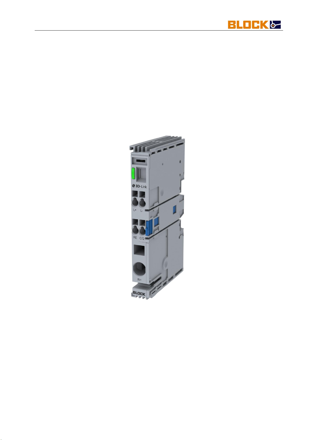
2.1 Description of the Communication Module................................................................................................ 4
2.2 System Design.............................................................................................................................................. 5
2.3 Dimensions .................................................................................................................................................. 6
2.4 Assembly...................................................................................................................................................... 6
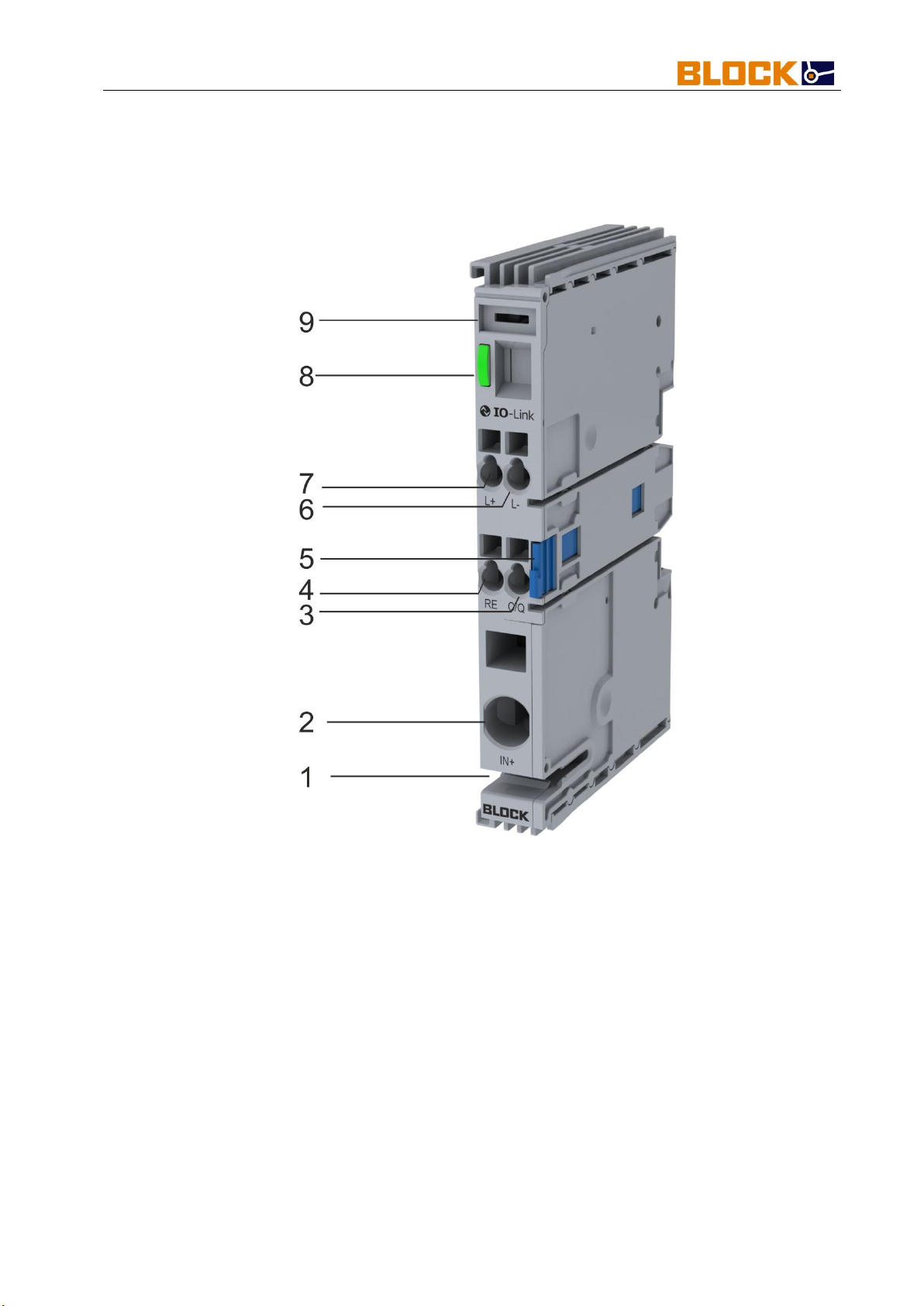
2.5 Connections and Signaling........................................................................................................................... 7
3. Initialization.......................................................................................................................................................... 8
3.1 Operating statuses....................................................................................................................................... 8
3.2 Communication ........................................................................................................................................... 9
4. Process Data and Parameters ............................................................................................................................ 10
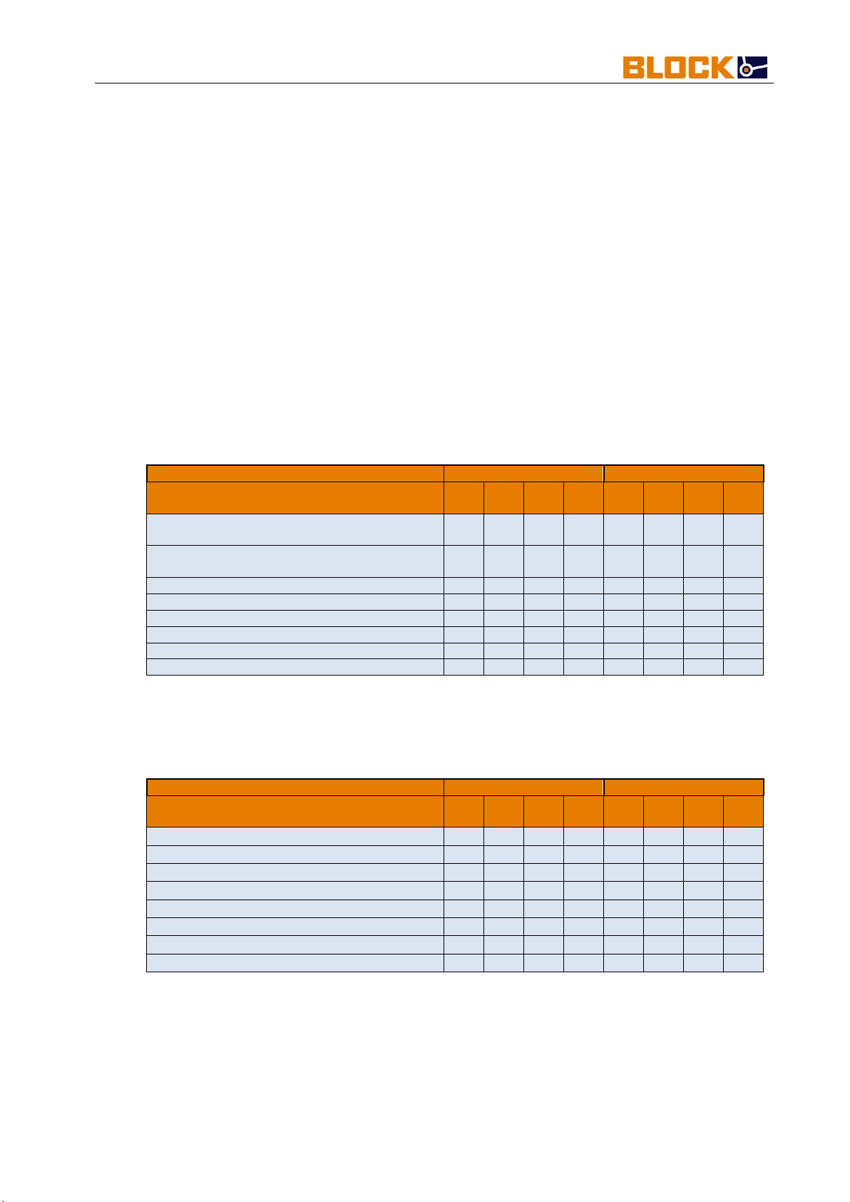
4.1 Process Data .............................................................................................................................................. 10
4.2 Acyclic I/O Data of the Communication Module.......................................................................................12
4.3 Acyclic I/O Data of the Network ................................................................................................................13
4.3.1 Coding of the Circuit Breaker Currents...................................................................................................... 14
4.3.2 Coding of the Circuit Breaker Status.......................................................................................................... 14
4.3.3 Coding of the Circuit Breaker Options....................................................................................................... 15
4.3.4 Coding of the Circuit Breaker Types ..........................................................................................................15
4.3.5 Coding of the Circuit Breaker Commands .................................................................................................16
4.3.6 Coding for Reset of the Circuit breaker Trip Counter................................................................................16

Manual V1.1
EB-IO-LINK
BLOCK Transformatoren-Elektronik GmbH
Max-Planck-Straße 36-46 27283 . Verden, Germany
17-06-20 / Schl
Subject to technical changes
Page: 3
1. General Information
1.1 Safety Instructions
Please read these warnings and safety instructions carefully before operating the
device. The device may only be installed by qualified competent personnel. In the
event of malfunctions or damage, switch off the supply voltage immediately and
send the device to Block to be checked. The device does not contain any service
components. When an internal fuse is triggered, there is most likely an internal
defect in the device. The data provided are for product description purposes only and
should not be construed as legally guaranteed properties.
1.2 Qualified Personnel
The product referred to in this documentation may only be operated by qualified
personnel, in compliance with the specific documentation, pertinent to the respective
task, in particular the safety instructions and warnings contained therein. Qualified
personnel can, as a result of their training and experience, help to ensure that the
use of the described product meets all safety requirements as well as applicable
regulations, provisions, standards, and laws.
1.3 Intended Use
This device is designed for installation within an enclosure and is suitable for use with
general electronic devices, such as industrial controls, office equipment,
communications equipment, and gages. Do not use this device in control systems for
airplanes, trains, or nuclear facilities where a malfunction can result in serious injury
or death.
1.4 Disclaimer
The contents of this publication have been checked with great care for concordance
with the described hardware and software. Nevertheless, there may be differences
between the product and the documentation. Deviations may also arise due to the
further development of the product.
For this reason, we cannot guarantee full concordance. Should this documentation
contain any errors, we reserve the right to make necessary corrections without prior
notice.

Manual V1.1
EB-IO-LINK
BLOCK Transformatoren-Elektronik GmbH
Max-Planck-Straße 36-46 27283 . Verden, Germany
17-06-20 / Schl
Subject to technical changes
Page: 4
2. Product Description
2.1 Description of the Communication Module
The EB-IO-LINK communication module serves as an interface for connection to a
higher-level controller and is compatible with circuit breakers of the variants EB-08,
EB-18, and EB-38.
The communication module supports IO-Link standard V1.1 and works with the COM
3 speed of 230.4 kB. The cyclic data exchange is 2.0 ms and contains 6 bytes of
process data.
To ensure error-free operation, the maximum number of 40 circuit breakers must not
be exceeded.

Manual V1.1
EB-IO-LINK
BLOCK Transformatoren-Elektronik GmbH
Max-Planck-Straße 36-46 27283 . Verden, Germany
17-06-20 / Schl
Subject to technical changes
Page: 5
2.2 System Design
Illustration 1 Establishing a Network with EB-GND4/8
Modules used in the system structure:
X1 EB-IO-LINK
F1 EB-0824-100-0
F2 EB-0824-100-0
F3 EB-0824-100-0
F3.1 EB-PMM
GND4 EB-GND4
GND8 EB-GND8
Note:
Deviations in the wiring can destroy the modules.
The IO-LINK cable must not exceed a maximum length of 20m.

Manual V1.1
EB-IO-LINK
BLOCK Transformatoren-Elektronik GmbH
Max-Planck-Straße 36-46 27283 . Verden, Germany
17-06-20 / Schl
Subject to technical changes
Page: 6
2.3 Dimensions
Illustration 2 Dimensions
2.4 Assembly
Illustration 3 Assembly

Manual V1.1
EB-IO-LINK
BLOCK Transformatoren-Elektronik GmbH
Max-Planck-Straße 36-46 27283 . Verden, Germany
17-06-20 / Schl
Subject to technical changes
Page: 7
2.5 Connections and Signaling
Illustration 4 Overview of Connections and Signaling
1) Mounting EB-BAR cross connector
2) Power terminal up to a max. of 40A
3) C/Q Communication
4) RE reset input
5) Unlocking latch
6) L- Communication
7) L+ Communication
8) LED Indicator
9) Labeling field

Manual V1.1
EB-IO-LINK
BLOCK Transformatoren-Elektronik GmbH
Max-Planck-Straße 36-46 27283 . Verden, Germany
17-06-20 / Schl
Subject to technical changes
Page: 8
3. Initialization
The EB-IO-LINK module initializes itself by applying the supply voltage to terminal IN
+ or by setting up the IO-Link connection.
Functional operation is only made possible by connecting circuit breaker modules and
applying the supply voltage to IN +.
After the supply voltage has been applied, all connected circuit breakers are
addressed one after the other and then selectively switched on, one after the other.
Using the IO-Link module, a maximum of 40 circuit breaker channels can be
addressed and managed.
To simplify initialization and configuration, the associated IODD can be downloaded
from the following via the following link.
Note:
When applying the supply voltage to IN+, it is imperative that a separate GND line is
connected to one of the circuit breaker channels.
Initialization without a series of circuit breaker modules can lead to faulty behavior.
3.1 Operating statuses
The EB-IO-LINK module has an LED to indicate the respective operating status.
Table 1 Operating Statuses
Operating Status
LED Indicator
Comments
Switched on, offline
Flashes green
Network is switched on and
addressed, no IO-Link
communication
Switched on, online
Green
Network is switched on and
addressed, IO-Link
communication is established
Off
Off
No supply voltage or IO-Link
connection

Manual V1.1
EB-IO-LINK
BLOCK Transformatoren-Elektronik GmbH
Max-Planck-Straße 36-46 27283 . Verden, Germany
17-06-20 / Schl
Subject to technical changes
Page: 9
3.2 Communication
The EB-IO-LINK communication module communicates according to the V1.1 IO-
LINK standard and is backwards compatible with the V1.0.1 IO-LINK standard.
For communication with the communication module and the connected network, a
version V1.1 or V1.0 IO-Link Master is required.
The communication module operates in COM 3 mode (230.4 kB) and exchanges 6
bytes of process data with the Master per cycle (2 ms).

Manual V1.1
EB-IO-LINK
BLOCK Transformatoren-Elektronik GmbH
Max-Planck-Straße 36-46 27283 . Verden, Germany
17-06-20 / Schl
Subject to technical changes
Page: 10
4. Process Data and Parameters
The EB-IO-LINK module has 6 bytes of process data which are exchanged with the
Master every 2 ms. The structure and arrangement of these data is discussed in
detail in Chapter 4.1.
The parameters and diagnostic data of each individual circuit breaker channel are
transmitted in addition to the process data, see chapter 4.2 and chapter 4.3.
4.1 Process Data
The process data is exchanged with the IO-Link Master in a cycle of 2ms with
230400 baud. The process data consists of a total of 6 bytes. The coding of the
individual bytes can be found in Tables 2-8.
Table 2 Process Data Collective Message Byte 1
Byte 1
MSB
LSB
Description
Bit
7
Bit
6
Bit
5
Bit
4
Bit
3
Bit
2
Bit
1
Bit
0
00 Collective Message Channel Tripped /
Switched Off
0
0
0
0
0
0
0
1
01 Collective Message Current >90%
Nominal
0
0
0
0
0
0
1
0
02 Group Reset
0
0
0
0
0
1
0
0
03 Internal Communication Failure*
0
0
0
0
1
0
0
0
04 Reserved
0
0
0
1
0
0
0
0
05 Reserved
0
0
1
0
0
0
0
0
06 Reserved
0
1
0
0
0
0
0
0
07 Input Voltage Alarm
1
0
0
0
0
0
0
0
*Bit will be set when the addressing was unsuccessful.
System restart required.
Table 3 Process Data eBreaker Tripped Byte 2
Byte 2
MSB
LSB
Description
Bit
7
Bit
6
Bit
5
Bit
4
Bit
3
Bit
2
Bit
1
Bit
0
08 eBreaker 01 Tripped
0
0
0
0
0
0
0
1
09 eBreaker 02 Tripped
0
0
0
0
0
0
1
0
10 eBreaker 03 Tripped
0
0
0
0
0
1
0
0
11 eBreaker 04 Tripped
0
0
0
0
1
0
0
0
12 eBreaker 05 Tripped
0
0
0
1
0
0
0
0
13 eBreaker 06 Tripped
0
0
1
0
0
0
0
0
14 eBreaker 07 Tripped
0
1
0
0
0
0
0
0
15 eBreaker 08 Tripped
1
0
0
0
0
0
0
0

Manual V1.1
EB-IO-LINK
BLOCK Transformatoren-Elektronik GmbH
Max-Planck-Straße 36-46 27283 . Verden, Germany
17-06-20 / Schl
Subject to technical changes
Page: 11
Table 4 Process Data eBreaker Tripped Byte 3
Byte 3
MSB
LSB
Description
Bit
7
Bit
6
Bit
5
Bit
4
Bit
3
Bit
2
Bit
1
Bit
0
16 eBreaker 09 Tripped
0
0
0
0
0
0
0
1
17 eBreaker 10 Tripped
0
0
0
0
0
0
1
0
18 eBreaker 11 Tripped
0
0
0
0
0
1
0
0
19 eBreaker 12 Tripped
0
0
0
0
1
0
0
0
20 eBreaker 13 Tripped
0
0
0
1
0
0
0
0
21 eBreaker 14 Tripped
0
0
1
0
0
0
0
0
22 eBreaker 15 Tripped
0
1
0
0
0
0
0
0
23 eBreaker 16 Tripped
1
0
0
0
0
0
0
0
Table 5 Process Data eBreaker Tripped Byte 4
Byte 4
MSB
LSB
Description
Bit
7
Bit
6
Bit
5
Bit
4
Bit
3
Bit
2
Bit
1
Bit
0
24 eBreaker 17 Tripped
0
0
0
0
0
0
0
1
25 eBreaker 18 Tripped
0
0
0
0
0
0
1
0
26 eBreaker 19 Tripped
0
0
0
0
0
1
0
0
27 eBreaker 20 Tripped
0
0
0
0
1
0
0
0
28 eBreaker 21 Tripped
0
0
0
1
0
0
0
0
29 eBreaker 22 Tripped
0
0
1
0
0
0
0
0
30 eBreaker 23 Tripped
0
1
0
0
0
0
0
0
31 eBreaker 24 Tripped
1
0
0
0
0
0
0
0
Table 6 Process Data eBreaker Tripped Byte 5
Byte 5
MSB
LSB
Description
Bit
7
Bit
6
Bit
5
Bit
4
Bit
3
Bit
2
Bit
1
Bit
0
32 eBreaker 25 Tripped
0
0
0
0
0
0
0
1
33 eBreaker 26 Tripped
0
0
0
0
0
0
1
0
34 eBreaker 27 Tripped
0
0
0
0
0
1
0
0
35 eBreaker 28 Tripped
0
0
0
0
1
0
0
0
36 eBreaker 29 Tripped
0
0
0
1
0
0
0
0
37 eBreaker 30 Tripped
0
0
1
0
0
0
0
0
38 eBreaker 31 Tripped
0
1
0
0
0
0
0
0
39 eBreaker 32 Tripped
1
0
0
0
0
0
0
0
Table 7 Process Data eBreaker Tripped Byte 6
Byte 6
MSB
LSB
Description
Bit
7
Bit
6
Bit
5
Bit
4
Bit
3
Bit
2
Bit
1
Bit
0
40 eBreaker 33 Tripped
0
0
0
0
0
0
0
1
41 eBreaker 34 Tripped
0
0
0
0
0
0
1
0
42 eBreaker 35 Tripped
0
0
0
0
0
1
0
0
43 eBreaker 36 Tripped
0
0
0
0
1
0
0
0
44 eBreaker 37 Tripped
0
0
0
1
0
0
0
0
45 eBreaker 38 Tripped
0
0
1
0
0
0
0
0
46 eBreaker 39 Tripped
0
1
0
0
0
0
0
0
47 eBreaker 40 Tripped
1
0
0
0
0
0
0
0

Manual V1.1
EB-IO-LINK
BLOCK Transformatoren-Elektronik GmbH
Max-Planck-Straße 36-46 27283 . Verden, Germany
17-06-20 / Schl
Subject to technical changes
Page: 12
4.2 Acyclic I/O Data of the Communication Module
The acyclic I/O data is information that can be queried directly by the EB-IO-LINK
communication module. The query is made using a function block provided by the
IO-LINK Master manufacturer.
In addition to the standard information (up to index 37), parameters can be specified
and retrieved here, as shown below in Table 8:
Table 8 Acyclic I/O Data
Index dec
Functions
Data
Type
Attribute
Comments
16
Vendor Name
String
RO
IO-Link Interface and
System Specification V1.1.2
17
Vendor Text
String
RO
IO-Link Interface and
System Specification V1.1.2
18
Product Name
String
RO
IO-Link Interface and
System Specification V1.1.2
19
Product ID
String
RO
IO-Link Interface and
System Specification V1.1.2
20
Product Text
String
RO
IO-Link Interface and
System Specification V1.1.2
21
Product Serial Number
String
RO
IO-Link Interface and
System Specification V1.1.2
22
Hardware Revision
String
RO
IO-Link Interface and
System Specification V1.1.2
23
Firmware Revision
String
RO
IO-Link Interface and
System Specification V1.1.2
24
Application Specific Tag
String
R/W
IO-Link Interface and
System Specification V1.1.2
32
Error Count
16 Bit
RO
IO-Link Interface and
System Specification V1.1.2
36
Device Status
8 Bit
RO
IO-Link Interface and
System Specification V1.1.2
37
Detailed Device Status
String
RO
IO-Link Interface and
System Specification V1.1.2
81
Gateway Options
8 Bit
R/W
Options of the
communication module
90
Input Voltage
16 Bit
RO
Input voltage level at the
power terminal
91
Number of Nodes
8 Bit
RO
Number of addressed
circuit breakers
100
ThresholdCriticalInputVoltageMax
16 Bit
R/W
Upper limit for input
voltage alarm
101
ThresholdCriticalInputVoltageMin
16 Bit
R/W
Lower limit for input
voltage alarm
102
Enable Events
8 to
R/W
Events for the first process
data byte

Manual V1.1
EB-IO-LINK
BLOCK Transformatoren-Elektronik GmbH
Max-Planck-Straße 36-46 27283 . Verden, Germany
17-06-20 / Schl
Subject to technical changes
Page: 13
4.3 Acyclic I/O Data of the Network
Acyclic I/O data is information that can be obtained directly from the circuit breaker
channels, shown below in Table 9.
The different codes for the data are shown below.
Table 9 Acyclic I/O Data Composite
Index dec
Functions
Data Type
Attribute
Comments
70
eBreaker RC_Status 1-8
8 Bit
RO
Check bit for the setting of
the current
71
eBreaker RC_Status 9-16
8 Bit
RO
Check bit for the setting of
the current
72
eBreaker RC_Status 17-24
8 Bit
RO
Check bit for the setting of
the current
73
eBreaker RC_Status 25-32
8 Bit
RO
Check bit for the setting of
the current
74
eBreaker RC_Status 33-40
8 Bit
RO
Check bit for the setting of
the current
80
eBreaker Command(ON/OFF/RESET)
8 Bit
WO
Switching on / Switching
off / Resetting the
individual circuit breakers
82
eBreaker Set Options to ALL
8 Bit
WO
Transfer the first circuit
breaker options to all
modules
83
eBreaker Reset Trip Counter 1-40
8 Bit
WO
Reset the trip counter.
Automatically 0 after
restart
201 – 240
eBreaker Trip Counter
8 Bit
RO
Trip counter of the circuit
breaker
301 – 340
eBreaker Current
16 Bit
RO
Actual current
401 – 440
eBreaker Trip Current
8 Bit
RW
Tripping current
501 – 540
eBreaker Status
8 Bit
RO
Status of the circuit
breaker (see Table 10)
601 – 640
eBreaker Software Version
16 Bit
RO
Software version of the
circuit breaker
701 – 740
eBreaker Options
16 Bit
RW
Options of the circuit
breaker
801 – 840
eBreaker Production Number
String
RO
Production number of the
circuit breaker
901 – 940
eBreaker Type
8 Bit
RO
Type designation of the
circuit breaker

Manual V1.1
EB-IO-LINK
BLOCK Transformatoren-Elektronik GmbH
Max-Planck-Straße 36-46 27283 . Verden, Germany
17-06-20 / Schl
Subject to technical changes
Page: 14
4.3.1 Coding of the Circuit Breaker Currents
Coding of the tripping currents (Index 401-416) is shown in Table 10:
Table 10 Coding of the Currents
Dec. value
Functions
Comments
0
Default
IODD DEFAULT
5
0.5
Tripping current 0.5A
10
1
Tripping current 1A
20
2
Tripping current 2A
30
3
Tripping current 3A
40
4
Tripping current 4A
50
5
Tripping current 5A
60
6
Tripping current 6A
80
8
Tripping current 8A
100
10
Tripping current 10A
4.3.2 Coding of the Circuit Breaker Status
Coding of the status (Index 501-540) is shown in Table 11:
Table 11 Coding of the Status
Dec. value
Functions
Comments
0
N.C.
Not connected
1
Switched Off
Switched off via interface
2
Switched On
Switched on
3
Tripped
Tripped
6
Current >90% Nominal
14
Current >100% Nominal
18
Tripped, Hardware Error
Hardware error
20
Tripped, thermal release
Thermal release
50
Switched Off, local
Switched off locally
Note:
If a circuit breaker was switched off locally, it can only be switched back on locally.
This functionality is used for safety purposes when working on the system.

Manual V1.1
EB-IO-LINK
BLOCK Transformatoren-Elektronik GmbH
Max-Planck-Straße 36-46 27283 . Verden, Germany
17-06-20 / Schl
Subject to technical changes
Page: 15
4.3.3 Coding of the Circuit Breaker Options
Coding of the options (Index 701 - 740) is shown in Table 12:
Table 12 Coding of Options
MSB1
LSB1
MSB0
LSB0
Description
Bit7
Bit6
Bit5
Bit4
Bit
3
Bit
2
Bit
1
Bit
0
Bit7
Bit6
Bit5
Bit4
Bit3
Bit2
Bit1
Bit0
Tripped /
Tripped OFF
0
0
0
0
0
0
0
0
0
0
0
0
0
0
0
1
OK inverted /
non inverted
0
0
0
0
0
0
0
0
0
0
0
0
0
0
1
0
Auto Addr On /
Off
0
0
0
0
0
0
0
0
0
0
0
0
0
1
0
0
Note:
The circuit breaker options correspond to delivery condition 3 (dec.) – i.e., the first
two options are set.
The "Auto Addr On / Off" option is only available as of the circuit breaker firmware
version 1.12 (RO) and indicates whether automatic address assignment is switched
on or off.
4.3.4 Coding of the Circuit Breaker Types
Coding of the types (Index 901-940) is shown in Table 13:
Table 13 Coding of Types
Dec. Value
Name
Type
Tripping Currents
170
EB-3824-100-0
Circuit breakers
Tripping currents can only be set via the
interface (0.5 - 10A)
138
EB-0824-100-0
Circuit breakers
Tripping currents adjustable via
interface or at the circuit breaker
(0.5 - 10A)
145
EB-1824-010-0
Circuit breakers
Fixed value 1A nominal
146
EB-1824-020-0
Circuit breakers
Fixed value 2A nominal
147
EB-1824-030-0
Circuit breakers
Fixed value 3A nominal
148
EB-1824-040-0
Circuit breakers
Fixed value 4A nominal
150
EB-1824-060-0
Circuit breakers
Fixed value 6A nominal
152
EB-1824-080-0
Circuit breakers
Fixed value 8A nominal
154
EB-1824-100-0
Circuit breakers
Fixed value 10A nominal

Manual V1.1
EB-IO-LINK
BLOCK Transformatoren-Elektronik GmbH
Max-Planck-Straße 36-46 27283 . Verden, Germany
17-06-20 / Schl
Subject to technical changes
Page: 16
4.3.5 Coding of the Circuit Breaker Commands
Coding of commands (Index 80) is shown in Table 30:
Table 14 Coding of Commands
Dec. Value
Name
Comments
1
ON
Channel 1 On
2
OFF
Channel 1 Off
3
RESET
Channel 1 Reset
6
ON
Channel 2 On
7
OFF
Channel 2 Off
8
RESET
Channel 2 Reset
11
ON
Channel 3 On
12
OFF
Channel 3 Off
13
RESET
Channel 3 Reset
…
…
…
Note:
The addresses of the channels are formed using an offset of decimal 5.
4.3.6 Coding for Reset of the Circuit breaker Trip Counter
The coding of the reset function (Index 83) for the trip counter is shown in
Table 30:
Table 15 Coding of the Reset
Dec. value
Functions
Comments
1
RESET
Channel 1 Reset Trip Counter
2
RESET
Channel 2 Reset Trip Counter
3
RESET
Channel 3 Reset Trip Counter
4
RESET
Channel 4 Reset Trip Counter
5
RESET
Channel 5 Reset Trip Counter
6
RESET
Channel 6 Reset Trip Counter
…
…
…
Note:
The addresses of the channels are formed using the channel numbers.
Table of contents
Other Block Control Unit manuals