Block EB-MODBUS-RTU User manual

Manual
EB-MODBUS-RTU
BLOCK Transformatoren-Elektronik GmbH
Max-Planck-Straße 36-46 27283 . Verden, Germany
10-23-17 / KRUT
Subject to technical changes
Page: 0
EB-MODBUS-RTU
Communication Module Between PLC/PC and EasyB
Single-Channel Circuit Breaker System
Collective Reset Input
2 Potential-Free
Collective Signaling
RS 485/RS 422
Interface

Manual
EB-MODBUS-RTU
BLOCK Transformatoren-Elektronik GmbH
Max-Planck-Straße 36-46 27283 . Verden, Germany
10-23-17 / KRUT
Subject to technical changes
Page: 1
Table of Contents
1. General Information .................................................................................................................2
1.1. Safety Instructions ................................................................................................................ 2
1.2. Qualified Personnel ..............................................................................................................2
1.3. Intended Use.........................................................................................................................2
1.4. Disclaimer ............................................................................................................................2
2. Product Description ................................................................................................................. 3
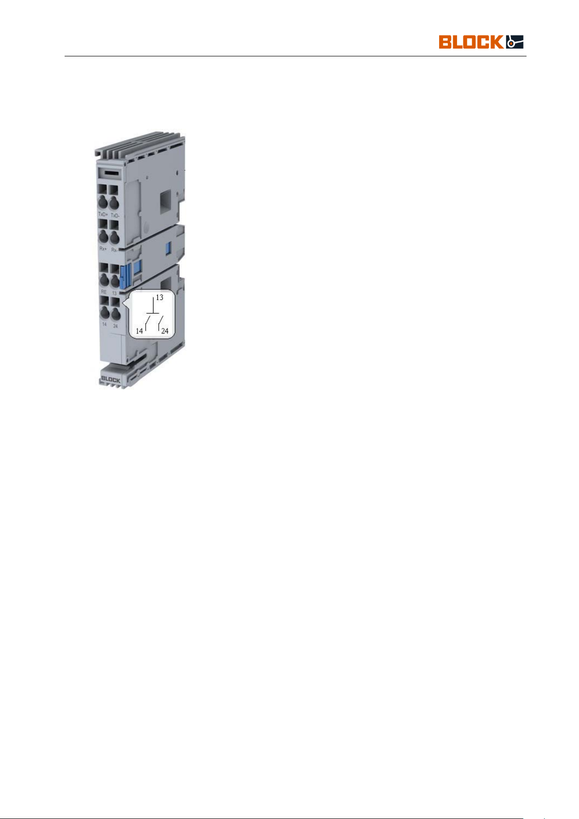
2.1. Description of the Communication Module.........................................................................3
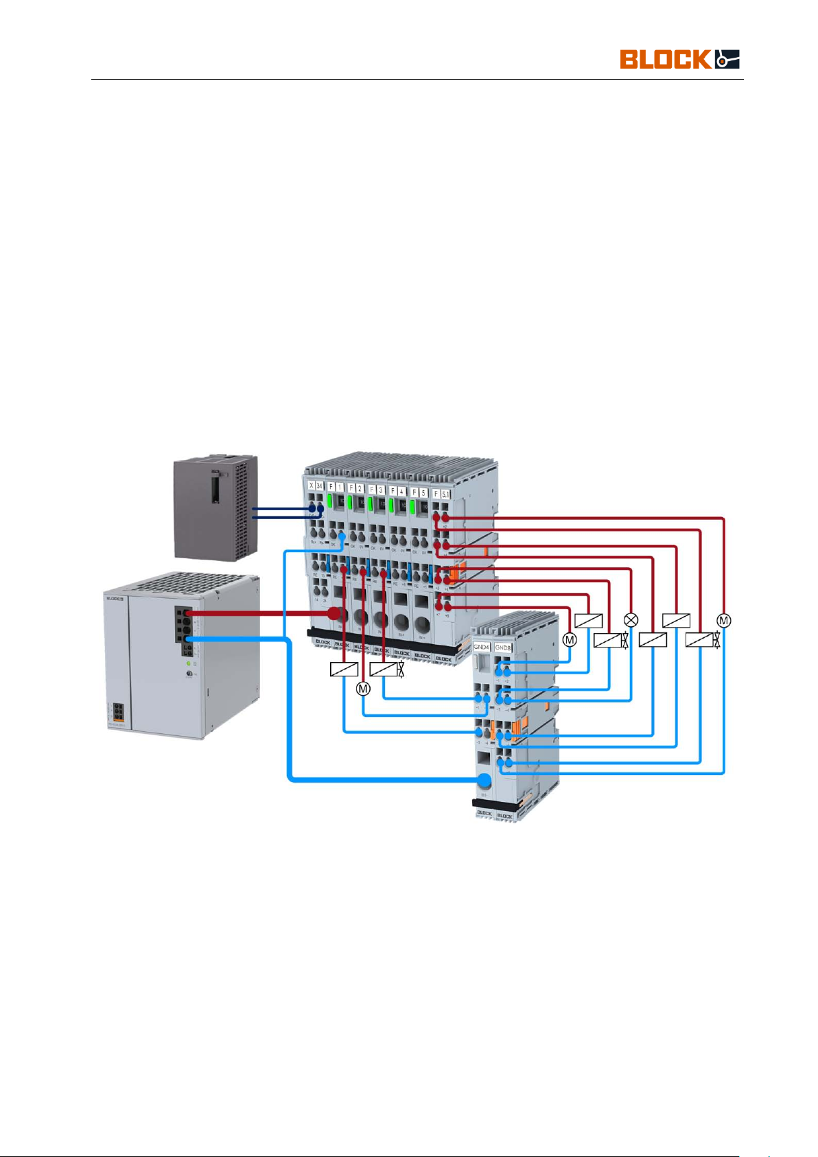
2.2. Functional Sketch.................................................................................................................3
2.3. Terminals.............................................................................................................................. 4
3. Initialization .............................................................................................................................4
4. Configuration ...........................................................................................................................5
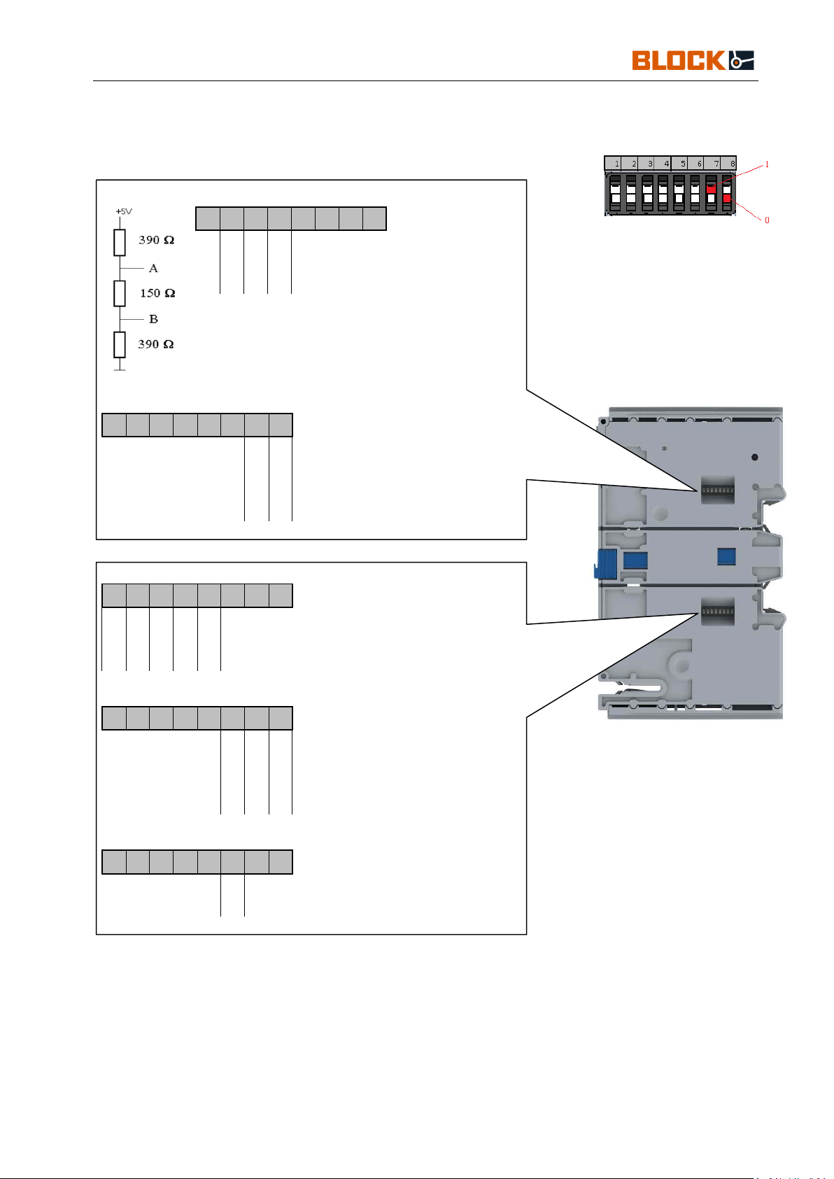
4.1. Dip switch ............................................................................................................................5
4.2. Byte Information ..................................................................................................................6
4.3. Configuration Example 2-Wire............................................................................................ 6
4.4. Configuration Example 4-Wire............................................................................................ 7
5. Communication and Examples ................................................................................................8
5.1. Loopback Diagnostic Test....................................................................................................8
5.2. Status Check.........................................................................................................................8
5.3. Error Message....................................................................................................................... 9
6. Register Overview..................................................................................................................10
6.1. EB-MODBUS-RTU ...........................................................................................................10
6.2. EB Single Channel Circuit Breaker....................................................................................11
6.3. EB Status Byte....................................................................................................................12
6.4. Coding of the Circuit Breaker Currents .............................................................................13
6.5. EB Variants ........................................................................................................................ 13
6.6. Options ...............................................................................................................................14
Please note, as of firmware 1.10 the status
byte has changed
Please note, as of firmware 1.10 the status
byte has changed

Manual
EB-MODBUS-RTU
BLOCK Transformatoren-Elektronik GmbH
Max-Planck-Straße 36-46 27283 . Verden, Germany
10-23-17 / KRUT
Subject to technical changes
Page: 2
1.General Information
1.1. Safety Instructions
Please read these warnings and safety instructions carefully before operating the device.
The device may only be installed by qualified competent personnel. In the event of
malfunctions or damage, switch off the supply voltage immediately and send the device to
Block to be checked. The device does not contain any service components. When an internal
fuse is triggered, there is most likely an internal defect in the device. The data provided are
for product description purposes only and should not be construed as legally guaranteed
properties.
1.2. Qualified Personnel
The product referred to in this documentation may only be operated by qualified personnel,
in compliance with the specific documentation pertinent to the respective task, in particular
the safety instructions and warnings contained therein. Qualified personnel can, as a result
of their training and experience, help to ensure that the use of the described product meets
all safety requirements as well as applicable regulations, provisions, standards, and laws.
1.3. Intended Use
This device is designed for installation within an enclosure and is suitable for use with
general electronic devices, such as industrial controls, office equipment, communications
equipment, and gages. Do not use this device in control systems for airplanes, trains, or
nuclear facilities where a malfunction can result in serious injury or death.
1.4. Disclaimer
The contents of this publication have been checked with great care for concordance with the
described hardware and software. Nevertheless, there may be differences between the
product and the documentation. Deviations may also arise due to the further development
of the product.
For this reason, we cannot guarantee full concordance. Should this documentation contain
any errors, we reserve the right to make necessary corrections without prior notice.

Manual
EB-MODBUS-RTU
BLOCK Transformatoren-Elektronik GmbH
Max-Planck-Straße 36-46 27283 . Verden, Germany
10-23-17 / KRUT
Subject to technical changes
Page: 3
2.Product Description
2.1. Description of the Communication Module
The EB-MODBUS-RTU communication module serves as an interface for connection to a
higher-level controller and is compatible with circuit breakers of the variants EB-08, EB-18,
and EB-38.
To ensure error-free operation, the maximum number of 40 circuit breakers must not be
exceeded.
2.2. Functional Sketch
Note:
•Deviations in the wiring can destroy the modules.

Manual
EB-MODBUS-RTU
BLOCK Transformatoren-Elektronik GmbH
Max-Planck-Straße 36-46 27283 . Verden, Germany
10-23-17 / KRUT
Subject to technical changes
Page: 4
2.3. Terminals
Communication
TxD+, TxD-, Rx+, Rx- 2/4-wire connections
Signal input
RE 24V collective reset input
Signal Contacts
13 Potential-free input
14 Channel triggered and/or switched off
24 Rated current at 90%
Care
IN+ supply voltage input +24VDC (18 - 30V)
3.Initialization
In order for the EB-MODBUS-RTU to communicate with the PLC, the appropriate dip-
switch configuration must be made.
The MODBUS module initializes itself by applying the supply voltage to terminal IN+.
Functional operation is only made possible by connecting circuit breaker modules and
then applying the supply voltage to IN+.
After the supply voltage has been applied, all connected circuit breakers are
addressed one after the other and then selectively switched on one after the other.
Using the EB-MODBUS-RTU module, a maximum of 40 circuit breaker channels can
be addressed and managed.
Note:
•When applying the supply voltage to IN+, it is imperative that a separate GND line is
connected to one of the circuit breaker channels.
•Initialization without a series of circuit breaker modules can lead to faulty behavior.

Manual
EB-MODBUS-RTU
BLOCK Transformatoren-Elektronik GmbH
Max-Planck-Straße 36-46 27283 . Verden, Germany
10-23-17 / KRUT
Subject to technical changes
Page: 5
4.Configuration
4.1. Dip switch
Connection: Receive 2/4-wire
1
2
3
4
5
6
7
8
1
0
Rx 2-Wire
0
1
Rx 4-Wire
Connection: Send 2/4-wire
End of frame time
1 2 3 4 5 6 7 8
0 0 3.5 Byte
0 1 10 ms
1 0 50 ms
1 1 500 ms
1 2 3 4 5 6 7 8
0
0
0
0
Term.+PullUp off
1
1
0
0
RS485 Term.+PullUp/Dn
1
1
1
1
RS422 Term.+PullUp/Dn
ModBus address
1 2 3 4 5 6 7 8
0 0 0 0 1
ModBus addr. 1
x x x x x
ModBus addr. X
1 1 1 1 1
ModBus addr. 31
Baud rate
1 2 3 4 5 6 7 8
0 0 9600 Bd
0 1 4800 Bd
1 0 19200 Bd
1 1 38400 Bd
Parity / stop bits
1
2
3
4
5
6
7
8
0
2 stop, no parity
1
1 stop, parity even

Manual
EB-MODBUS-RTU
BLOCK Transformatoren-Elektronik GmbH
Max-Planck-Straße 36-46 27283 . Verden, Germany
10-23-17 / KRUT
Subject to technical changes
Page: 6
4.2. Byte Information
•1 Start bit
The information byte consists of:
•8 Information bits
•2 stop bits without parity bit or 1 stop, parity bit even
4.3. Configuration Example 2-Wire
2-wire send / receive
EOF = 10 ms
ModBus addr. 1
19200 Bd
1
2
3
4
5
6
7
8
1
2
3
4
5
6
7
8
1
1
0
0
1
0
0
1
0
0
0
0
1
0
1
0
Slave
EB-MODBUS-RTU
Rx+
Rx- Tx+ Tx-
Rx-
Master
Tx+
Tx-
Rx+

Manual
EB-MODBUS-RTU
BLOCK Transformatoren-Elektronik GmbH
Max-Planck-Straße 36-46 27283 . Verden, Germany
10-23-17 / KRUT
Subject to technical changes
Page: 7
4.4. Configuration Example 4-Wire
2-wire send / receive
EOF = 10 ms
ModBus addr. 1
19200 Bd
1
2
3
4
5
6
7
8
1
2
3
4
5
6
7
8
1
1
1
1
0
1
0
1
0
0
0
0
1
0
1
0
Slave
EB-MODBUS-RTU
Rx+
Rx- Tx+ Tx-
Rx-
Master
Tx+
Tx-
Rx+

Manual
EB-MODBUS-RTU
BLOCK Transformatoren-Elektronik GmbH
Max-Planck-Straße 36-46 27283 . Verden, Germany
10-23-17 / KRUT
Subject to technical changes
Page: 8
5.Communication and Examples
5.1. Loopback Diagnostic Test
MODBUS
DATA
MODBUS
Addr. Function CRC-L CRC-H Telegram: Master ->
Slave
1
8
0
0
AA
55
5E
94
MODBUS
DATA
MODBUS
Addr. Function CRC-L CRC-H Telegram: Slave ->
Master
1
8
0
0
AA
55
5E
94
5.2. Status Check
Interrogate circuit breaker 1 via EB-MODBUS-RTU
MODBUS
DATA
MODBUS
Addr. Function r/w Start Addr.
Number of
States
CRC
Telegram:
Master -> Slave
Byte
Byte
h-byte
l-byte
h-byte
l-byte
l-byte
h-byte
1
1
1
245
0
1
150
122
CRC
Number of selected circuit breakers
(devices/register addresses always 1)
Circuit breaker 1, status (register address 501)
See: "Overview of Single Channel Circuit Breaker Functions"
Reading the Outputs
MODBUS RTU Address

Manual
EB-MODBUS-RTU
BLOCK Transformatoren-Elektronik GmbH
Max-Planck-Straße 36-46 27283 . Verden, Germany
10-23-17 / KRUT
Subject to technical changes
Page: 9
5.3. Error Message
Addr.
Function
Data
Description
X Func. + 0x80 1 Use of an unsupported short code
2 Use of an unauthorized memory register
3 Wrong value
6
Device cannot process request at the
moment. Repeat request later
8 Field is read-only

Manual
EB-MODBUS-RTU
BLOCK Transformatoren-Elektronik GmbH
Max-Planck-Straße 36-46 27283 . Verden, Germany
10-23-17 / KRUT
Subject to technical changes
Page: 10
6.Register Overview
The following data can be set or retrieved via EB-MODBUS-RTU.
6.1. EB-MODBUS-RTU
Table 1: EB-MODBUS-RTU Register Overview
Query Response
Function
Starting
Address Value Description
Query status output 14 1
READ_COIL_Status 1
0x00 Off
0x01 Switched off by circuit breaker function (tripped)
Query status output 24 2
READ_COIL_Status 1
0x00 Off
0x01 Switched on, current above warning threshold (90% nominal
current)
Query device ID
4
READ_HOLDING_REGISTERS 3
1-2. byte Firmware version
3-6. byte Production order
7-10. byte Serial number
11-12. byte Variant (see
EB variants)
Query options
5
READ_HOLDING_REGISTERS 3
high byte Options (see Options)
low byte Options (see Options)
high byte Options Complement (see Options)
low byte Options Complement (see Options)
Query supply voltage 6
READ_HOLDING_REGISTERS 3
high byte Voltage in mV
low byte Voltage in mV
Set options
5
For all devices in the network
WRITE_MULTIPLE_REGISTERS
16
high byte
Options (see Options)
low byte Options (see Options)
high byte Options Complement (see Options)
low byte Options Complement (see Options)

Manual
EB-MODBUS-RTU
BLOCK Transformatoren-Elektronik GmbH
Max-Planck-Straße 36-46 27283 . Verden, Germany
10-23-17 / KRUT
Subject to technical changes
Page: 11
6.2. EB Single Channel Circuit Breaker
Table 2: Register overview for EB-0824-100-0, EB-1824-xxx-0 and EB-3824-100-0
Query Response
Function
Circuit Breakers
Starting Address
Value
Description
Query status output OK
1
-
40
101
-
140
READ_COIL_Status 1 Off
On
Query status only
1
40
201
-
240
READ_HOLDING_REGISTERS
3
high byte
see EB status byte
Query actual current 1 40 301 - 340
READ_HOLDING_REGISTERS 3 high byte in mA
low byte in mA
Query nominal current
1
-
40
401
-
440
READ_HOLDING_REGISTERS
3
high byte
in mA
low byte in mA
Query combination status 1 - 40 501 - 540
READ_HOLDING_REGISTERS
3
1. byte
Status of EB-MODBUS-RTU signaling contacts
0x00
No events
0x01 Signal contact 14 (off / tripped)
0x02 Signal contact 24 (nominal current> = 90%)
2. byte EB circuit breaker status
See EB status byte
3-4. byte
EB circuit breaker actual current
high byte in mA
low byte in mA
5-6. byte EB circuit breaker nominal current
high byte
in mA
low byte
in mA
7-8. byte EB-MODBUS-RTU Power Supply
high byte in mV
low byte in mV
Query device ID 1 - 40 601 - 640
READ_HOLDING_REGISTERS 3 1-2. byte Firmware version
3-6. byte Production order
7-10. byte Serial number
11-12. byte Variant (see
EB variants)
Query options
1
-
40
701
-
740
READ_HOLDING_REGISTERS 3 high byte Options (see Options)
low byte Options (see Options)
high byte Options Complement (see Options)
low byte Options Complement (see Options)
Set status 1 - 40 501 - 540
WRITE_SINGLE_REGISTER 6 0x01 Off
0x02 On
0x04 Reset
Set status
All
500
For all devices in the network
WRITE_SINGLE_REGISTER
6
0x01
Off
0x02 On
0x04 Reset
Set nominal current 1 - 40 401 - 440
WRITE_SINGLE_REGISTER 6 high byte Nominal current in mA
low byte
Nominal current in mA
Set options 1 - 40 701 - 740 Only for one device
WRITE_MULTIPLE_REGISTERS 16 high byte Options (see Options)
low byte Options (see Options)
high byte Options Complement (see Options)
low byte
Options Complement (see Options)

Manual
EB-MODBUS-RTU
BLOCK Transformatoren-Elektronik GmbH
Max-Planck-Straße 36-46 27283 . Verden, Germany
10-23-17 / KRUT
Subject to technical changes
Page: 12
6.3. EB Status Byte
Coding of the status (Index 501 - 540) is shown in Table 2
Table 3: Coding of the Status (as of protection switch version 1.10)
7 6 5 4 3 2 1 0 Meaning LED
No communication
off
off (by user/ PLC) lights up
R
on
lights up
E Switched off by circuit breaker function (tripped) flashes
S
Switched on, current above warning threshold (90% nominal current)
flashes
E Switched on, current above warning threshold (100% nominal current) flashes
R
off, hardware error (fuse)
flashes
V off, thermal release flashes
E
off locally, (by key) as of circuit breaker version 1.12
lights up
RC (rotary wheel position)
Note:
•If a circuit breaker was switched off locally, it can only be switched back on locally.
This functionality is used for safety purposes when working on the system.
•As of protection switch version 1.10, the status byte has changed!
Bits 7 and 6 occur separately in the status byte. For this reason, all bits in the status
byte must be evaluated individually.

Manual
EB-MODBUS-RTU
BLOCK Transformatoren-Elektronik GmbH
Max-Planck-Straße 36-46 27283 . Verden, Germany
10-23-17 / KRUT
Subject to technical changes
Page: 13
6.4. Coding of the Circuit Breaker Currents
Coding of the tripping currents (registers 401 - 440) is shown in Table 2
Table 4: Coding of the Tripping Currents
Value Meaning
500 Tripping current 0.5 A
1000 Tripping current 1 A
2000 Tripping current 2 A
3000 Tripping current 3 A
4000 Tripping current 4 A
5000 Tripping current 5 A
6000 Tripping current 6 A
8000 Tripping current 8 A
10000 Tripping current 10 A
6.5. EB Variants
Coding of the options (registers 601-640) is shown in Table 2
Table 5: Coding of the Types
Name Value Description
EB-MODBUS-RTU 0xCC10 MODBUS-RTU Communication Module
EB-IO-LINK 0xCC20 IO-LINK Communication Module
EB-3824-100-0 0xCBAA Tripping currents can only be set via the interface (0.5 - 10A)
EB-0824-100-0 0xCB8A Tripping currents adjustable via interface or at the circuit breaker (0.5 -0A)
EB-1824-010-0 0xCB91 Fixed value 1A nominal
EB-1824-020-0 0xCB92 Fixed value 2A nominal
EB-1824-030-0 0xCB93 Fixed value 3A nominal
EB-1824-040-0 0xCB94 Fixed value 4A nominal
EB-1824-060-0 0xCB96 Fixed value 6A nominal
EB-1824-080-0 0xCB98 Fixed value 8A nominal
EB-1824-100-0 0xCB9A Fixed value 10A nominal

Manual
EB-MODBUS-RTU
BLOCK Transformatoren-Elektronik GmbH
Max-Planck-Straße 36-46 27283 . Verden, Germany
10-23-17 / KRUT
Subject to technical changes
Page: 14
6.6. Options
Coding of the options (registers 701-740) is shown in Table 2
Table 6: Coding of Options
H-Byte L-Byte
NR Bit Value 7 6 5 4 3 2 1 0 7 6 5 4 3 2 1 0 Meaning
1 1 Switched off or signaled as tripped
0 Signal as tripped only
2 1 OK signal inverted
0
Do not invert OK signal
3 1
Switch Automatic Addressing off
0
Switch Automatic Addressing on
Note:
•The circuit breaker options correspond to delivery condition 3 (dec.) – i.e., the first
two options are set.
•The "Automatic Addressing on/off" option is only available with protection switch
version 1.10 and enables the automatic address assignment of an already addressed
group when the supply voltage is switched off.

Manual
EB-MODBUS-RTU
BLOCK Transformatoren-Elektronik GmbH
Max-Planck-Straße 36-46 27283 . Verden, Germany
10-23-17 / KRUT
Subject to technical changes
Page: 15
Option Example
Bit-No.
15
14
13
12
11
10
9
8
7
6
5
4
3
2
1
0
Options
set
delete everything
Options Complement
reset
Bit-No.
15
14
13
12
11
10
9
8
7
6
5
4
3
2
1
0
Options
set
no change
Options Complement
1
1
1
1
1
1
1
1
1
1
1
1
1
1
1
1
reset
Switched off or signaled as tripped
Bit-No.
15
14
13
12
11
10
9
8
7
6
5
4
3
2
1
0
Options
1
set
activate only,
the rest remain unchanged
Options Complement
1
1
1
1
1
1
1
1
1
1
1
1
1
1
1
1
reset
Invert OK signal
Bit-No.
15
14
13
12
11
10
9
8
7
6
5
4
3
2
1
0
Options
1
set
activate only,
the rest remain unchanged
Options Complement
1
1
1
1
1
1
1
1
1
1
1
1
1
1
1
1
reset
Activate: Invert OK signal
Activate: Signal as tripped only
Bit-No.
15
14
13
12
11
10
9 8 7 6 5 4 3 2 1 0
Options
1
set
activate,deactivate,
the rest remain unchanged
Options Complement
1
1
1
1
1
1
1
1
1
1
1
1
1
1
1
reset
Table of contents
Other Block Control Unit manuals
Popular Control Unit manuals by other brands

Afag
Afag LM 12/30 Assembly and operating instructions

Boge
Boge base control operating instructions

schmersal
schmersal AES 9107 operating instructions

Pfeiffer Vacuum
Pfeiffer Vacuum TPG 500 operating instructions

Samson
Samson 3351 Mounting and operating instructions

LIFE home integration
LIFE home integration VISIO manual

V2
V2 KIT EASY LUX manual

Sanken
Sanken SLA7070MMPR Series Application Information

Whelen Engineering Company
Whelen Engineering Company E-2010 Operation & installation manual

Sierra Wireless
Sierra Wireless AirPrime SL8080 Hardware integration guide

WAGO
WAGO 750-8212/040-010 manual

SSS Siedle
SSS Siedle FPM 611-02 Product information