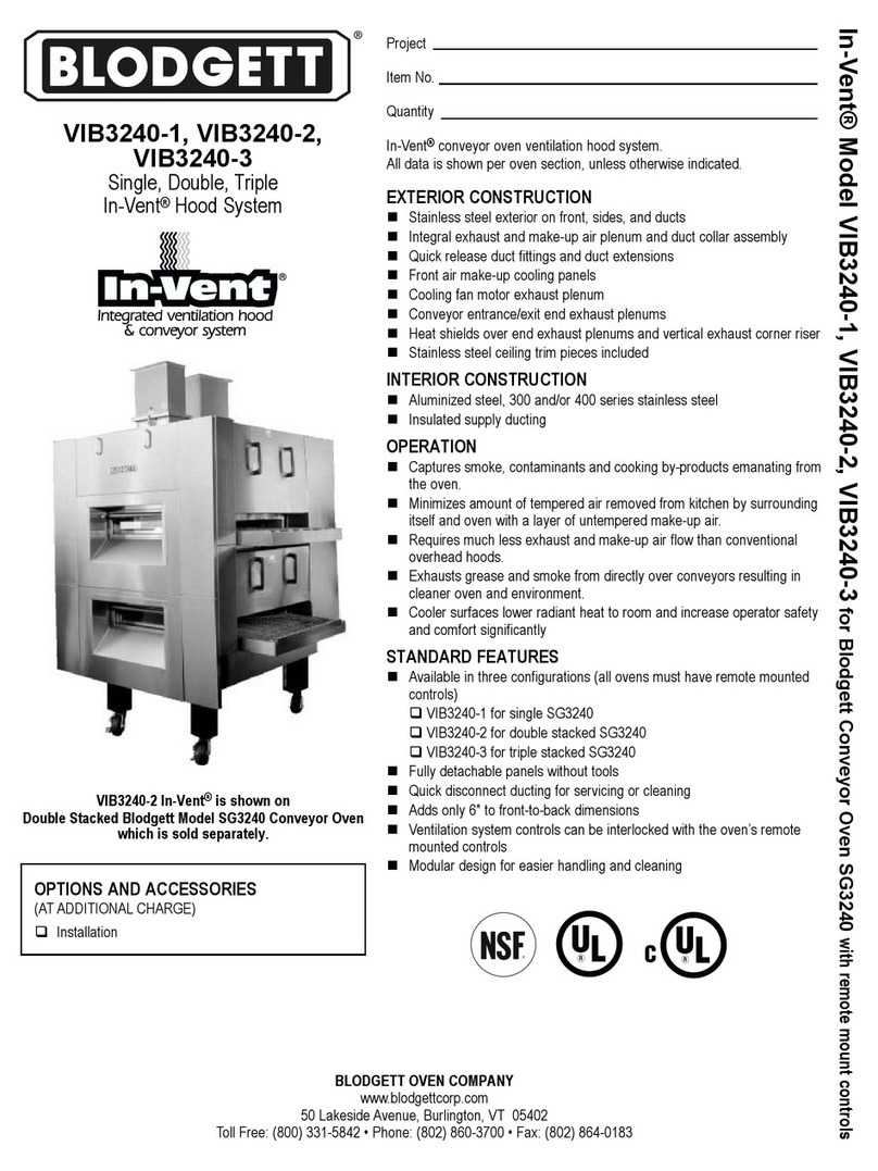
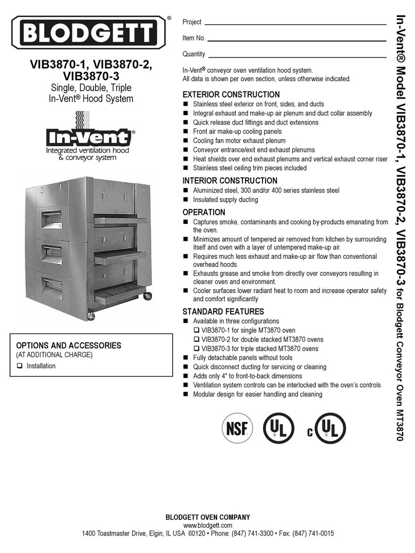
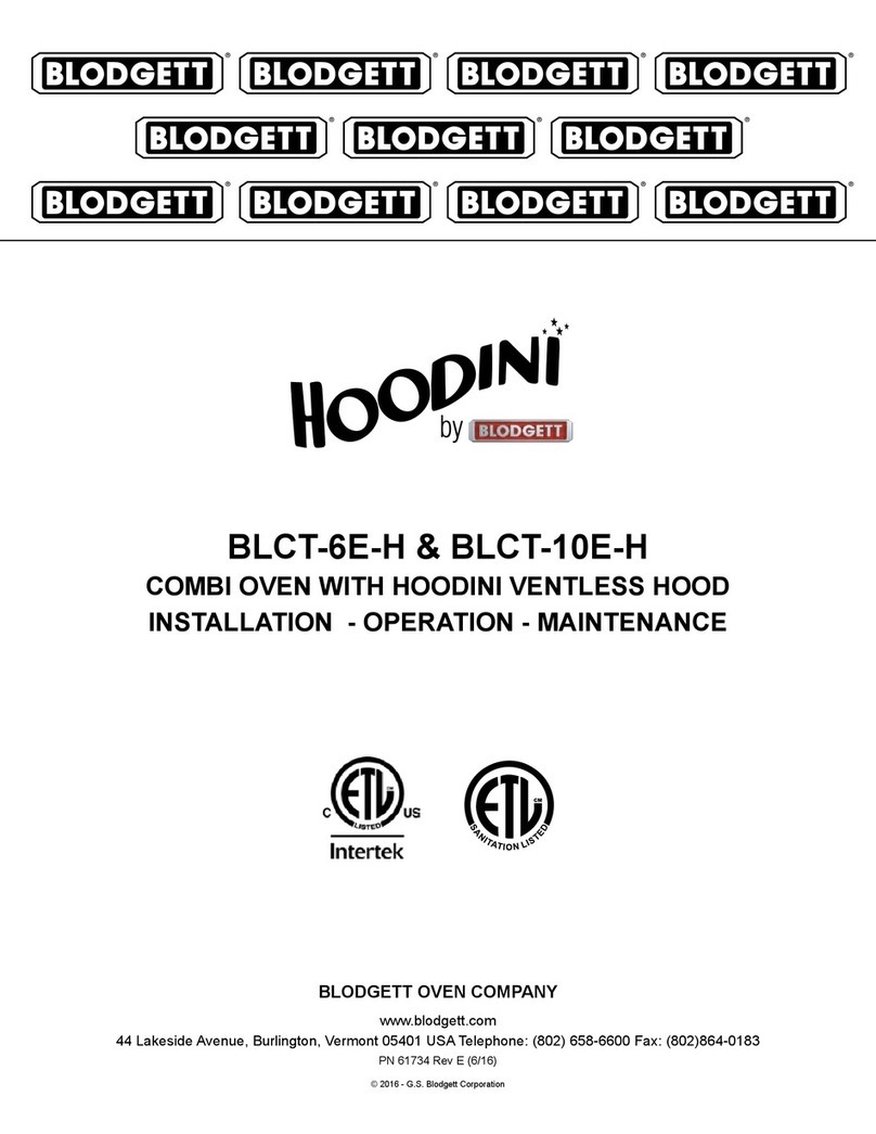
Blodgett VLF Owner's manual

VLF
VENTLESS HOOD FOR
FULL SIZE ELECTRIC CONVECTION OVENS
INSTALLATION - OPERATION - MAINTENANCE
BLODGETT OVEN COMPANY
www.blodgett.com
42 Allen Martin Drive, Essex Junction, Vermont 05452 USA Telephone: (802) 658-6600 Fax: (802)864-0183
PN 100825 Rev A (12/19)
© 2019 - G.S. Blodgett Corporation
UL
KNLZ
LISTED
E499012

TABLE OF CONTENTS
INSTALLATION
Utility Connections - Standards and Codes ......................................................................1
Delivery & Inspection ..........................................................................................2
Connection to Electric Convection Oven.........................................................................3
OPERATION
Ventless Hood Control Panel ...................................................................................7
Sequence of Operation ....................................................................................... 8
MAINTENANCE
Filter Replacement ............................................................................................9
Cleaning ....................................................................................................10

1
Installation
Utility Connections - Standards and Codes
THE INSTALLATION INSTRUCTIONS CONTAINED
HEREIN ARE FOR THE USE OF QUALIFIED INSTAL-
LATION AND SERVICE PERSONNEL ONLY. INSTAL-
LATION OR SERVICE BY OTHER THAN QUALIFIED
PERSONNEL MAY RESULT IN DAMAGE TO THE
BLODGETT EQUIPMENT AND/OR INJURY TO THE
OPERATOR.
Qualied installation personnel are individuals, a rm,
a corporation, or a company which either in person or
through a representative are engaged in, and responsible
for:
• the installation of electrical wiring from the electric
meter, main control box or service outlet to the elec-
tric appliance.
Qualied installation personnel must be experienced in
such work, familiar with all precautions required, and have
complied with all requirements of state or local authorities
having jurisdiction.
EPA 202 Test Method
Using EPA test method 202, emissions of grease laden
vapors were measured at 0.6 mg/m3 for bone-in, skin on,
quartered chickens. Results are less than the established
5 mg/m3 standard.
U.S. and Canadian installations
Installation must conform with local codes, or in the ab-
sence of local codes, with the National Electrical Code,
ANSI/NFPA 70-Latest Edition and/or Canadian National
Electric Code C22.1 as applicable.
Australia and general export installations
Installation must conform with Local and National instal-
lation standards. Local installation codes and/or require-
ments may vary. If you have any questions regarding
the proper installation and/or operation of your Blodgett
equipment, please contact your local distributor. If you do
not have a local distributor, please call the Blodgett Oven
Company at 0011-802-658-6600.
WARNING!!
This device can ONLY be placed on Blodgett
ELECTRIC convection ovens. DO NOT install
onto gas ovens.
UL
KNLZ
LISTED
E499012

2
Installation
Delivery & Inspection
DESCRIPTION AND SPECIFICATIONS
The VLF ventless hood provides all of the cooking capa-
bilities of the best in class Blodgett convection oven with-
out the need for a kitchen ventilation hood. Please refer
to the owner’s manual of your Blodgett convection oven
for detailed instruction on the operation of the oven.
DELIVERY AND LOCATION
All Blodgett equipment is shipped in containers to prevent
damage. Upon delivery of your new equipment:
• Inspect the shipping container for external damage.
Any evidence of damage should be noted on the
delivery receipt which must be signed by the driver.
• Uncrate the equipment and check for internal dam-
age. Carriers will accept claims for concealed dam-
age if notied within fteen days of delivery and the
shipping container is retained for inspection.
The Blodgett Oven Company cannot assume responsibil-
ity for loss or damage suered in transit. The carrier as-
sumed full responsibility for delivery in good order when
the shipment was accepted. We are, however, prepared
to assist you if ling a claim is necessary.

3
Installation
Connection to Electric Convection Oven
Complete the setup procedure for the single or double
stack convection oven as described in the oven owner’s
manual prior to installing the VLF on top of the oven.
The following instructions describe the installation of
the VLF onto the convection oven:
UNCRATING AND STACKING
1. Carefully uncrate the VLF.
2. Place the VLF hood onto the convection oven’s body-
top. This may require two people.
Figure 1
INSTALLING THE VENT EXIT
Move the vent exit on the rear of the hood from its ship-
ping location to the operation location as follows.
1. Loosen the screws and lift the vent exit to remove it.
2. Reinstall it over the large rectangular hole on the rear
of the hood.
3. Tighten the screws.
Shipping Location
Operating Location
Figure 2

4
Installation
Connection to Electric Convection Oven
INSTALLING THE DUCTING TO THE OVEN
1. There are 4 unique ducting kits based on oven con-
guration.
100 standard depth ovens single & double stack 200 bakery depth ovens single & double stack
Figure 3
2. Install the ducting using the hardware provided.
• For single stack units the opening on the right
will be covered with a blocking plate.
• For double stack units the vent riser will be con-
nected to the opening on the right.
Connect to single or top oven Blocked for single, connect to
vent riser for double stack
Figure 4

5
Installation
WIRING THE VLF HOOD
The VLF ventless hood is prewired. All electrical connec-
tions are made to the 4 or 6 conductor cables coming out
of the ventless hood.
• The hood draws power from a single oven or the top
oven of a double stack and uses the 6 conductor
cable.
• The bottom oven of a double stack uses the 4 con-
ductor cable.
• All electrical connections are made in the oven(s).
The VLF has one 6 conductor cable running out of the
upper strain relief on the back. This will be connected to
either a top oven of a double stack or a single oven.
1. Remove the nut from the strain relief and loosen the
strain relief’s grip on the 6 conductor cable.
2. A hole adjacent to the motor connection cable strain
relief on the back of the oven has a plastic plug. Re-
move this plug.
3. Install the strain relief into the hole with the nut.
4. Wiring for Mark-V and Zephaire-E ovens are dier-
ent. Make the connections to the oven’s lever nuts
according to the following table.
NOTE: The green wire from the 6 conductor cable
goes into the oven’s copper ground lug.
VLF
Blue BL-40 BL-40
Black BR-40 BR-40
Green Ground Lug Ground Lug
White Gray (to Motor) Gray (to Motor)
White w/
Black Stripe
Gray (to Motor) Gray (to Motor)
Red GY-1 Y-1
Red w/
Black Stripe
GY-2 Y-2
Before Making Wiring Connections
After Making Wiring Connections
Figure 5
Connection to Electric Convection Oven

6
Installation
Connection to Electric Convection Oven
5. If the oven is a double stack, connect the 4 conduc-
tor cable coming out of the back of the VLF’s bottom
strain relief to the bottom oven of the double stack
oven following the bottom table below.
VLF
White Gray (to Motor) Gray (to Motor)
White w/
Black Stripe
Gray (to Motor) Gray (to Motor)
Red GY-1 Y-1
Red w/
Black Stripe
GY-2 Y-2
6. After the electrical connections are made tighten the
grip on the newly installed strain reliefs on the back
of the oven.
7. Route and secure the cable(s) with the supplied jiy
clip(s) to the back of the oven(s) as shown.
Figure 6

7
Operation
Ventless Hood Control Panel
Figure 7
1
2
3
4
CONTROL DESCRIPTION
1. Hood is on and operating properly.
2. Filter is beginning to clog. Order and replace lter.
The oven remains operational.
3. Filter is completely clogged. Oven will not heat until
4. CIRCUIT BREAKER - Must be in the ON position for
hood to run.
OPERATION
1. Ensure circuit breaker is in the ON position. The hood
will run with the oven’s convection fan(s).
WARNING!!
If the red indicator light on the hood is illumi-
nated the oven/ovens will not heat. All func-
tions of the oven will continue to work except

8
Operation
Sequence of Operation
1. The VLF ventless hood receives power from the eld
wiring block of a single, or top of a double stack, vent-
less ready oven. This received power runs to the
front panel circuit breaker of the VLF and must be in
the ON position in order for the hood to operate.
2. The VLF has an interlock switch that engages when
the hood’s lter is properly installed. The lter inter-
lock switch must also be engaged in order for the
hood to operate.
3. Provided 1 and 2 above are satised, turning on ei-
ther the top or bottom ventless ready oven of a double
stack or the single ventless ready oven will start the
oven’s convection blower motor, closing the motor’s
proof of rotation switch which will turn on the hood’s
blower motor.
4. When the VLF blower turns on it creates a pressure
dierential between the plenum above and the ple-
num below the hood’s lter. The upper and lower
plenum pressure taps are connected to two pressure
switches, one has a pressure setpoint of 0.40”W.C.
and the other has a pressure setpoint of 0.25”W.C.
The 0.40”W.C. pressure switch is interlocked with the
oven’s call for heat. For a new lter, the dierential
pressure is low because airow is nearly uninhibited.
This very low pressure will cause no change in either
switch, which will allow the oven to heat and operate
normally.
5. As the VLF’s lter becomes obstructed through use,
the dierential pressure across the lter will rise.
When this dierential pressure reaches 0.25”W.C.,
the orange indicator light, labeled “Order New Filter”,
will illuminate on the front panel of the hood
6. As the VLF’s lter becomes further obstructed from
usage, the dierential pressure will continue to rise.
When this dierential pressure reaches 0.40”W.C.,
the red indicator light, labeled “Change Filter To Use
Oven”, will illuminate on the front panel of the hood.
Once the red indicator is illuminated the oven’s/ov-
ens’ call for heat will disengage. The oven(s) will still
operate but will not heat.

9
Maintenance
Filter Replacement
The lter on the VLF needs to be replaced as it becomes
clogged with grease and particulates given o by the
cooking process. -
pending on the amount and types of foods cooked in
an oven.
The indicator lights will tell you when it is time to replace
your lter.
• When the ORANGE indicator lights it is time to order
a new lter. Both the orange and green indicator
remain lit and the oven will continue to function.
Replace the lter as soon as possible.
• If the lter is not changed, eventually the RED indi-
cator light with illuminate. This indicates that the lter
is too clogged to eectively remove particulates and
grease laden vapor from the cooking exhaust. If the
red indicator light is illuminated the oven/ovens
will not heat.
HOW TO REPLACE THE FILTER
1. Turn o the oven/ovens and the breaker on the front
of the VLF.
2. Remove the front panel of the hood using the han-
dles. Lift straight up until the retaining hooks are free.
Next, pull the panel away from the oven.
Figure 8
3. The lter will spring out for easy removal.
NOTE: Ifthelterisseverlycloggedwithexcessive
greasebuildup,itmaynotspringout.Inthis
case,atoolmayberequiredtoremoveit.
4. Discard the used lter. DO NOT try to clean and re-
It will not function properly.
5. Install the new lter.
a. Make sure the arrows on the edge of the lter are
pointing up.
b. Push the lter all the way in. It is spring loaded
and will stick out approximately 1” from the face
of the hood.
Be sure the arrows on the edge of the lter
are pointing up
Figure 9
6. Reinstall the front panel by aligning the hooks on the
back of the panel with the notches in the hood. Pull
down to secure.
Notch in Hood
Hook on Cover
Figure 10
7. Turn on the oven(s) and the breaker on the front of
the VLF. The green indicator light should illuminate
indicating that the hood is back up and running.

10
Maintenance
Cleaning
It is critical to keep the oven cavities clean when operating with a ventless hood. The ventless hood is intended to capture
grease laden vapor, not smoke. An oven cavity that is not properly cleaned, free of debris, and charred food scraps, will
produce smoke. Ensure that your oven is cleaned regularly.
Figure 11
Table of contents
Other Blodgett Ventilation Hood manuals
Popular Ventilation Hood manuals by other brands

German pool
German pool 2100 operating instructions

German pool
German pool GPR-GY900L user manual

Air King
Air King Advantage Series ProHood operating manual

VentAHood
VentAHood PYH302266 installation instructions

Air King
Air King ESVAL30 Important instructions & operating manual

Universal Blue
Universal Blue Campana T 60 instruction manual