Blonder tongue BT QAM PRO User manual

CATV Analyzer
INSTRUCTION MANUAL
BT QAM PROBT QAM PRO
ww
w.blondertongue.com

2
3 – FRONT PANEL & KEYS
4 – NAVIGATION
4 – CONFIGURATIONS
6 – “PLAN” SCREEN AND NAVIGATION
7 – QUALITY MEASUREMENT SCREEN
8 – ANALOG TV MEASUREMENT SCREEN
8 – DIGITAL CATV MEASUREMENT SCREEN
9 – INGRESS & LEAKAGE MEASUREMENT SCREENS
10 – SPECTRUM ANALYZER SCREENS
11 – TV: BARSCAN LEVEL/POWER OF ALL CHANNELS
12 – SCAN: CHANNEL PLANS AND LOG FILES
12 – TV: AUTOMEMORY TV
13 – TV: MANUAL MEMORY
15 – LOGGER SAVE & RECALL
16 – BATTERY TEST & BATTERY REGENERATION
17 – LI-ION POLYMER BATTERIES
17 – WARNINGS
18 – POWER SUPPLY & BATTERY CHARGE LED STATUS
18 – METER MAINTENANCE
18 DISPOSAL of ELECTRONIC EQUIPMENT
19 – LIMITED WARRANTY
Index
______________________________________________________________________________

3
N. Name Function
1 HOME Key Press to turn on. Keep pressed to turn off.
2 MAINS
LED on when the meter is connected to the USB power supply
3 SPECT Key Press to display spectrum
4 DC@RF LED DC@RF indicator
5 BAT. CHRG LED on during battery charge
6 QUALITY Key Press to display signal quality
7 RF TV Input TV/CATV input connector 5-1,000 MHz
8 Arrow keys Press to select and adjust values/fields
9 ENTER Press to select/confirm
10 USB/Power Supply 5 V power supply connector via MICRO-USB
and for PC connection
Front Panel & Keys
_____________________________________________________
NOTE :
This meter can be charged and used directly from a PC via the USB socket, or using any
MICRO-USB, 5V, 1A power supply.
7
6
4
5
2
3
9 8
1
10

4
• ENTER
• ARROW KEYS
Navigation ____________________________________________________________________________
Press to
select a menu
or to confirm.
Press the arrow
keys to select the
menu required or
to adjust the value
in a selected field
(number/menu).
• POWER
To turn on
press the
‘HOME’ key.
To turn off, press and
hold the ‘HOME’ key.
• RESET HARDWARE • RESET SOFTWARE
With the meter
turned on keep the
‘HOME’ key pressed
for 10 seconds and
then turn on again.
With the meter turned
off, turn the instrument on
keeping the “ENTER” key
pressed and only release
when the boot has been
completed.
Press the ‘HOME’ key, use the arrow keys to select “CONFIG”, then press “ENTER”.
Use the arrow keys to select and adjust the settings/values in the various menus.
Configurations_________________________________________________________________________

5
Discovery variables are QAMB Only, QAMA Only (N/A for USA), VSB (8VSB for Broadcast/
OTA) and All Mod..
All Mod. includes all prior digital modulation schemes.
All schemes include Analog. Using All Mod. will make the discovery time take longer as the
meter searches through more modulation possibilities to find a match.
The typical setting when using the meter on a CATV feed is USACAB and QAMB.
NOTE: This setting also populates the Master TV Plan parameter on page 8.
CONFIGURATION OF THE INSTRUMENT’S PARAMETERS:
COUNTRY CONFIGURATION & DISCOVERY MODE:
LEAKAGE PARAMETERS CONFIGURATION:
INGRESS PARAMETERS CONFIGURATION:
BARSCAN PARAMETERS CONFIGURATION:

6
“PLAN” Screen and Navigation
___________________________________________
Press the “HOME” key, use the arrow keys to select “PLAN”, then press “ENTER”.
Use the UP/DOWN arrow keys to select the TV MASTER (Tv MASTER PLAN) memory
plans you wish to use, manual (MANUAL MEMORY) or automatic (AUTOtv MEMORY).
Use the TvMaster Plan when the formats of channels to be measured are not known.
The meter will “auto discover” based on settings done under Country Configurations and
Discovery Mode set up on page 5.
MASTER TV PLAN SELECTION:
MANUAL MEMORY SELECTION:
AUTO MEMORY SELECTION:

7
QUALITY measurement screen
____________________________________________
Measure the quality and power of up to 140 channels in blocks of 8 channels.
Press the arrow keys to scroll the channel list.
Select the manual
memory plan required
(MANU XX).
Select the automatic
memory plan required
(AUTO XX).
or
DIGITAL CHANNEL: ANALOG CHANNEL:
POWER
QUALITY
LEVEL
A/V

8
TV
__________________________________________________________________________________
TV SIGNAL ANALYSIS
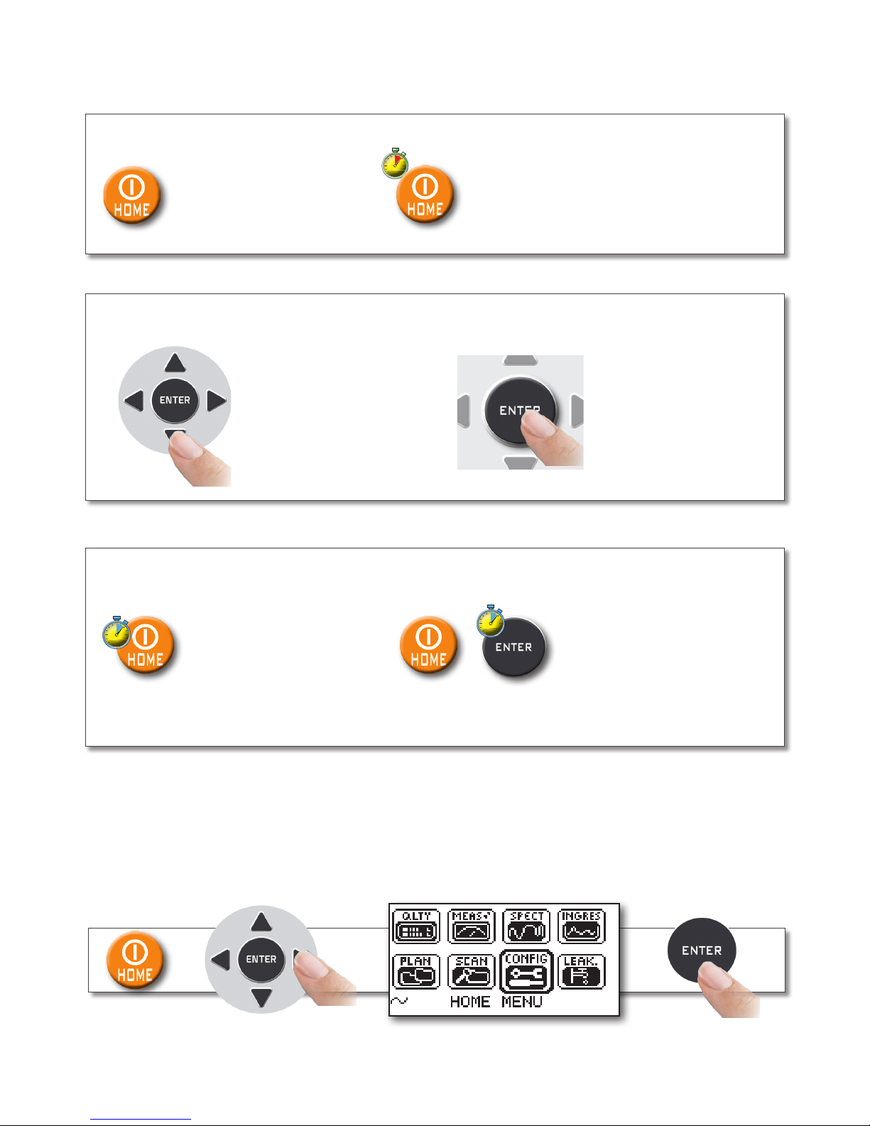
Press the “HOME” key, use the arrow keys to select “MEAS”, then press “ENTER”.
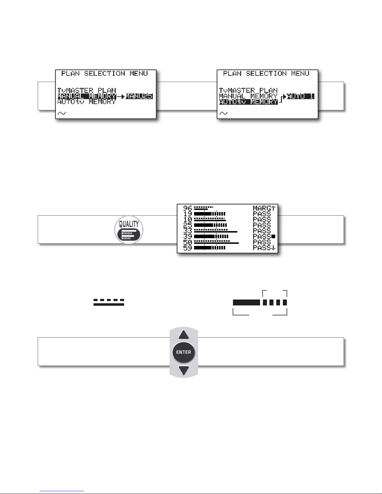
Or press the “QUALITY” key
for 2 seconds and release.
Analog TV Measurement screen
_______________________________
Use the “LEFT” and “RIGHT” keys to select the field required.
Use the “UP” and “DOWN” arrow keys to adjust the value. Keep pressed to rapidly adjust.
Signal Level (LEV) Report
carrier VIDEO-AUDIO (V/A)
Digital CATV Measurement screen
___________________________
Repeatedly press the “ENTER” key to navigate in the TV measurement screens.
Use the “LEFT” & “RIGHT” keys to select the field required.
Use the “UP” & “DOWN” arrow keys to adjust the value.
Keep pressed to rapidly adjust.
Digital Average Power (PWR)
Noise Margin (N.MAR)
Quality (QLY)
MER
BER before Viterbi (bBER)
BER after Viterbi (aBER)
QAM Constellation
Press to navigate
in the TV
measurements

9
INGRESS MEASUREMENT SCREEN
___________________________
LEAKAGE MEASUREMENT SCREEN
___________________________
Press the “HOME” key, use the arrow keys to select “INGRESS”, then press “ENTER”.
Press the “HOME” key, use the arrow keys to select “LEAK”, then press “ENTER”.

10
SPECT
___________________________________________________________________________
Or press the “HOME” key, use the arrow keys to select “SPECT”, then press “ENTER”.
Press the “SPECT” key to go to Spectrum mode
Spectrum analyzer
SPECTRUM ANALYZER SCREENS
______________________________
DIGITAL TV SIGNALS
SPECTRUM
ANALOG TV SIGNALS
SPECTRUM
Press to cycle through
spectrum analyzer
screens
Use the arrow keys to select and adjust the spectrum’s
numerical values: SPAN (SP) - CHANNEL - FREQUENCY (F) -
REFERENCE LEVEL
Fast spectrum
(PEAK SPECTRUM)
Fast spectrum
(PEAK SPECTRUM)
Fast spectrum with memory
peak (HOLD SPECTRUM)
Fast spectrum with memory
peak (HOLD SPECTRUM)

11
TV: BARSCAN level/power of all channels
_______________
Barscan (level bar chart)
Use the arrow keys to select and change the
barchart’s numerical values:
SPAN (SP) - CHANNEL - FREQUENCY (F) -
RESOLUTION (dB/D) - REFERENCE LEVEL
In the TV standard channelization the meter displays the level/power of all TV channels.
In MANUAL MEMORY or AUTOMATIC TV MEMORY (AUTOtv MEMORY) the meter displays
the memorized channels and distinguishes analog and digital signals using two different
bars.
ANALOG
CHANNELS
DIGITAL
CHANNELS
Press the “SPECT” key for 2
seconds to visualize the Barchart

12
Use the arrow keys to
select and change the
required parameters
select
“AUTOMEMORY TV”
Fig 2
Memorization in progress
Fig 3
Memorization complete
Select “DESTINAT” and select the destination file “AUTO” where the search must be saved
(f i g 1).
Select “DISCOVERY” and set search mode (fig 1),
Select “LEVEL” and set the minimum level threshold of the analog channels searched (fig 1).
Select “POWER” and set the minimum power level of the digital channels searched (fig 1).
Select “START” to create a new channel plan and to activate the search (fig 1).
NOTE:
If the word “OVERWRITE” appears, the selected file will be overwritten.
Wait a few minutes (fig 2), the meter indicates the recorded ANALOG & DIGITAL CHannels
(fig 3).
To automatically store all the existing channels in a city or building.
Press the “HOME” key, using the arrow keys select “SCAN”, then press ENTER.
Fig 1
Set the desired parameters
and select “START”
TV: AUTOMEMORY TV
_________________________________________________
SCAN: channel plans and log files
____________________________

13
TV: MANUAL MEMORY
______________________________________________
Use the “UP” and “DOWN’” keys and
choose the channel required
(for example “07”)
Use the “LEFT” and “RIGHT” keys and
select the item “PLAN”
(in the example “CblQAM”)
Use the “LEFT” and “RIGHT” keys
and select the item “CHANNEL”
(in the example “T7”)
Use the “UP” and “DOWN’” keys and
choose the manual plan required
(for example “MANU 6”)
User must select MANUAL MEMORY in the PLAN menu (page 6) before changes can be
made here.
“THIS PLAN IS NOT MODIFIABLE” message will be displayed if the PLAN is not Manual.
How to create/edit a manual memory plan:
Select “MANUAL MEMORY” and press “ENTER”
Press the “HOME” key, use the arrow keys to select “SCAN”, then press “ENTER”.

14
Channel “07” now is memorized in
memory position “P 1”/”MANU 6”
Use the “LEFT” and “RIGHT” keys and
select “STORE”, then press “ENTER”
to memorize
Use the “UP” and “DOWN’” keys and
choose the value of constellation
required (for example “QAM64”)
Use the “LEFT” and “RIGHT” keys and select the item “SR” (Symbol Rate)
(in the example “SR5.057”).
Use the “UP” and “DOWN’” keys to choose the value of symbol rate required
(selectable only in QAM-A mode)
Use the “LEFT” and “RIGHT” keys and
select the item “CONSTELLATION”
(in the example “QAM256”)
NOTE: When the memorization of a channel has finished, follow the steps described above
to add other channels in the same memory plan, or in a new one.
The instrument automatically suggests the zone “MEM ..: Pxx: ___”, the memory position
where you can save or overwrite the new channel.
Use the “LEFT” and “RIGHT” keys and select
the item “MODULATION” (in the example
“TV QAM-B”). Use the “UP” and “DOWN’” keys
and select the type of modulation required
Use the “LEFT” and “RIGHT” keys
and select the item “FREQUENCY”
(in the example “F177.00”).
Use the “UP” and “DOWN’” keys
and select the frequancy required

15
LOGGER
_________________________________________________________________________
LOGGER SAVE
______________________________________________________________
LOGGER RECALL
__________________________________________________________
Use the arrow keys to select and change the items/values in the various menus.
Press the “HOME” key, use the arrow keys to select “SCAN”, then press “ENTER”.
Set the desired parameters and select
“STORE?” to create a new LOG file.
“DATA LOGGER” in progress.
Select the “LOG” (LOG NUM) number
to be recalled and select “RECALL”.
Select “Logger RECALL”
and press “ENTER”.
Press the arrow keys to select the
measurement of the required signal.
Select LOGGER SAVE
and press “ENTER”.
NOTE:
If the word “OVERWRITE” appears, the selected log will be overwritten.
Wait a few minutes for the Datalogger to complete.

16
THIS PROCEDURE EXPLAINS HOW TO REGENERATE/CHECK YOUR BATTERIES AND CALIBRATE THE
BATTERY CHARGE INDICATOR
USEFUL ADVICE:
•CHARGETHEBATTERIESEVERYNIGHTAFTERUSE,EVENIFTHEYARENOTCOMPLETELY
DISCHARGED;
•ALWAYS USE THE “BATTERY SAVE” & “TIMER OFF” FUNCTIONS TO INCREASE YOUR METER’S
AUTONOMY;
•THEMAXIMUMCAPACITYOFTHEBATTERIESANDBATTERYCHARGEINDICATOR’SACCURACY
IMPROVES BY UP TO 20% IF YOU CARRY OUT MANY BATTERY TEST CYCLES;
•DONOTREPLACETHEBATTERIES:FIRSTCARRYOUT3TO5BATTERYTESTCYCLESUNTILYOU
RECOVER THE MAXIMUM CAPACITY OF THE BATTERIES.
“BATTERY TEST” INSTRUCTIONS & PROCEDURE:
1. Before carrying out the test, connect the meter to the battery charger:
• Turn on the meter;
• Press the Home key (fig. 1);
• Select the word “CONFIG” and press “ENTER” to confirm (fig. 1);
• Select “METER SETUP” and press “ENTER” (fig. 2);
• Select the word “BATT. TEST” and press the “RIGHT” keys to select “ON”;
• Press “ENTER” to confirm.
• Carefully read the various screens, pressing “ENTER” in succession;
• In the last instructions window, select “START” and press “ENTER” to start the test.
WARNING: the procedure will be cancelled if you select “exit” on any screen.
Battery Test & Battery Regeneration
______________________
FIG. 2*F I G . 1* FIG. 3*
220 BBLY
IMPORTANT ADVICE:
• Do not connect any type of load to the “F” input connector (LNB, TV head-end, amplifiers, etc.).
2. The battery test takes approx. 12 hours (charging/discharging/recharging activities and
measurement of the battery autonomy), during this time the meter must not be used. At the end of
the test the meter will turn off automatically. In order to make sure that the test has been carried
out correctly, all the meter’s commands are blocked except for the reset function, which remains
active so that the meter can be turned off if necessary.
3. The batteries will be completely charged at the end of the test.
4. To check the battery test results, enter “METER SETUP” (fig. 2), select “BATTERY TEST” function
and read the results: for example 220BBLY (fig. 3) = 220 minutes. The “Y” of YES confirms that the
battery is still good enough, whereas an “N” for NO indicates that it could be faulty, too deteriorated
or that the cycle was interrupted.
IMPORTANT NOTES:
If the test is interrupted using “reset”, the battery charge indicator may provide incorrect indications,
therefore repeat the battery test procedure.
This device contains a built-in Li-Po (Lithium polymer) battery that can be recharged many times.
The battery contains chemicals that might wear with time even if not used. Please dispose of
batteries properly.
Do not take the battery pack apart or expose it to extreme temperatures (over 50°C). If the device
has been exposed to very low or high temperatures, let it rest at room temperature before use.
The Battery must be recharged at room temperature (about 20°C) with the device turned off. To
avoid premature failure of the battery never leave the device with an empty battery for prolonged
periods.
RECHARGEABLE BATTERY _______________________________
RECHARGING THE BATTERY______________________________
WARNINGS
______________________________________________________

17
This device contains a built-in Li-Po (Lithium polymer) battery that can be recharged many times.
The battery contains chemicals that might wear with time even if not used. Please dispose of
batteries properly.
Do not take the battery pack apart or expose it to extreme temperatures (over 50°C). If the device
has been exposed to very low or high temperatures, let it rest at room temperature before use.
The Battery must be recharged at room temperature (about 20°C) with the device turned off. To
avoid premature failure of the battery never leave the device with an empty battery for prolonged
periods.
RECHARGEABLE BATTERY _______________________________
RECHARGING THE BATTERY______________________________
WARNINGS
______________________________________________________
IMPORTANT:
• ALWAYS TURN THE INSTRUMENT OFF BEFORE CONNECTING THE BATTERY CHARGER;
• DO NOT LEAVE THE BATTERIES DISCHARGED FOR LONG PERIODS;
• ALWAYS CHARGE THE BATTERIES AT NIGHT FOR AT LEAST 7 HOURS, EVEN IF THEY ARE
NOT COMPLETELY DISCHARGED.
USEFUL INFORMATION:
1. The batteries supplied are high quality and tested individually, their autonomy depends on the
following conditions:
– the external temperature: with temperatures of less than 10°C, 20% of the capacity is lost;
– the age of the batteries: a 10% loss in efficiency each year;
– Remember that the TIMER OFF function, that automatically turns off the Meter after
5 o 10 minutes of inactivity, saves up to 30%.
2. The battery indicator has a tolerance (like all battery powered electronic devices) according to
the following factors:
- the battery’s charging percentage;
- external temperatures;
- battery wear and tear;
• +/– 2%.
ICONS SHOWING THE BATTERY CHARGE STATUS:
FULLFULL <80%<80% <30%<30% <10%<10%<50%<50%
LI-ION Polymer Batteries
____________________________________________
BATTERY AUTONOMY:
The battery
autonomy is about 3 hours.

CLEANING THE METER
Keeping the meter clean from dust and dirt is easy and helps maintain optimum working conditions over the
years. The cleaning procedure is quick and simple and requires only minor attention.
Never use strong, chemical products (diluent) and/or abrasive materials, which may damage plastics and
displays.
Always use a soft cloth, dampened with a solution of water and alcohol or a de-greasing, non-abrasive liquid soap.
The keyboard and display should be gently cleaned. Rubbing the keyboard and/or the display(s) may seriously
damage their functions.
MAINTENANCE AND CARE OF THE METER
This meter has been designed to withstand severe conditions of use. Even so, its life can be prolonged by
respecting some simple and effective rules:
• Themeterhasnotbeendesignedtowithstandhightemperatures(over60°Cor140°F).Thesetemperatures
can be easily reached when the meter is left in a car, especially behind the windshield, or in a trunk. The LCD
display and/or other details could easily be damaged by extreme temperatures.
• Theinternalbatterycouldrapidlylooseitsefficiencyifexposedtohighorlowtemperatures.
This may result in reduced meter autonomy when powered by its internal battery.
• Whenrechargingtheinternalbattery,allowgoodaircirculationaroundthemeterandtheadapter:donot
cover it with clothes and do not recharge the battery when the meter is in its transport case.
• Themeterisnotwaterproof,evenifitisprotectedagainstincidentalwaterdrops.Ifitcomesintocontactwith
water electronic circuits may be damaged. Allow the meter to dry thoroughly before trying to turn it on. Do
not use hairdryers or other strong heating sources, just leave the meter at room temperature. If necessary,
contact Rover Laboratories S.p.A. for technical assistance.
Meter Maintenance
____________________________________________________
Disposal of electric / electronic equipment (applicable in all CEE countries and wherever a separate
waste collection system is applied).
This symbol on the packaging indicates that the product should not be considered
domestic waste. The product, at the moment of disposal, should be brought to
a waste collection point with the proper facilities to manage electrical/electronic
appliances. Electric/electronical appliances, if not disposed of correctly, may have
negative consequences on your health and the enivironment.
Furthermore, a proper recycling procedure helps mantain natural resources. For
more information about the correct disposal of this product, please refer to your
local waste disposal management offices or the shop where this product was bought.
Disposal of Electronic Equipment
_____________________________
Power Supply (mains) and Battery Charge (chrg)
LED status
____________________________________________________________________
INSTRUMENT
CONNECTED
TO THE MAINS
POWER SUPPLY
LED MAINS LED BATT CHRG NOTES
OFF YES ON ON Batteries in fast charge
OFF YES ON OFF Battery charge completed
OFF YES ON
Flashing
0.5 SECONDS OFF
0.5 SECONDS ON
Abnormal battery temperature.
The recharge cycle has been suspended
automatically and will automatically reset.

19
Limited Warranty
_________________________________________________________
Seller will at its sole option, either repair or replace (with a new or factory reconditioned product, as Seller may determine) any product
manufactured or sold (or in the case of software, licensed) by Seller which is defective in materials or workmanship or fails to meet the
applicable specifications that are in effect on the date of shipment or such other specifications as may have been expressly agreed upon
in writing: (i) for a period of three (3) years from the date of original purchase for all stock hardware products (other than those specifically
referenced herein below having a shorter warranty period); (ii) for a period of one (1) year from the date of original purchase, with respect to all
MegaPort™, IPTV products, test equipment and fiber optics receivers, transmitters, couplers and integrated receiver/distribution amplifiers; (iii) for
a period of one (1) year from the date of original purchase (or such shorter period of time as may be set forth in the license agreement specific
to the particular software being licensed from Seller) with respect to all software products licensed from Seller (other than Core Product Software)
that is (a) developed for a specific function or application, (b) complimentary to and does not function without the Core Product Software, and
(c) listed with a specific model number and stock number in Seller’s Price List (“Non-Core Software”); (iv) for a period of ninety (90) days from the
date of original purchase, with respect to non-serialized products and accessories, such as parts, sub-assemblies, splitters and all other products
sold by Seller (other than Core Product Software and Refurbished/Closeout Products) not otherwise referred to in clauses (i) through (iii) above.
The warranty period for computer programs in machine-readable form included in a hardware product, which are essential for the functionality
thereof as specifically stated in the published product specifications (“Core Product Software”) will be coincident with the warranty period of the
applicable hardware product within which such Core Product Software is installed.
Software patches, bug fixes, updates or workarounds do not extend the original warranty period of any Core Product Software or Non-Core
Software. Notwithstanding anything herein to the contrary,
(i) Seller’s sole obligation for software that when properly installed and used does not substantially conform to the published specifications in
effect when the software is first shipped by Seller, is to use commercially reasonable efforts to correct any reproducible material non-conformity
(as determined by Seller in its sole discretion) by providing the customer with: (a) telephone or e-mail access to report non-conformance so
that Seller can verify reproducibility, (b) a software patch or bug fix, if available or a workaround to bypass the issue if available, and (c) where
applicable, replacement or damaged or defective external media, such as CD-ROM disk, on which the software was originally delivered;
(ii) Seller does not warrant that the use of any software will be uninterrupted, error-free, free of security vulnerabilities or that the software will meet
the customer’s particular requirements; and the customer’s sole and exclusive remedy for breach of this warranty is, at Seller’s option, to receive
(a) suitably modified software, or part thereof, or (b) comparable replacement software or part thereof;
(iii) Seller retains all right, title and interest in and to and ownership of all software (including all Core Product Software and Non-Core Software)
including any and all enhancements, modifications and updates to the same; and
(iv) in some cases, the warranty on certain proprietary sub-assembly modules manufactured by third-party vendors and contained in Seller’s
products, third party software installed in certain of Seller’s products, and on certain private–label products manufactured by third-parties for
resale by Seller, will be of shorter duration or otherwise more limited than the standard Seller limited warranty.
In such cases, Seller’s warranty with respect to such third-party proprietary sub-assembly modules, third-party software and private-label
products will be limited to the duration and other terms of such third-party vendor’s warranty, if any. In addition, certain products, that are not
manufactured by Seller, but are resold by Seller, may carry the original OEM warranty for such products, if any.
The limited warranty set forth above does not apply to any product sold by Seller, which at the time of sale constituted a Refurbished/Closeout
Product, the limited warranty for which is provided in the following paragraph.
Seller will at its sole option, either repair or replace (with a new or factory-reconditioned product, as Seller may determine) any product sold by
Seller which at the time of sale constituted a refurbished or closeout item (“Refurbished/Closeout Product”), which is defective in materials or
workmanship or fails to meet the applicable specifications that are in effect on the date of shipment of that product or fails to meet such other
specifications as may have been expressly agreed upon in writing between the parties, for a period of ninety (90) days from the date of original
purchase.
Notwithstanding the foregoing, in some cases the warranty on certain proprietary sub-assembly modules manufactured by third-party
vendors and contained in Seller products, third party software installed in certain of Seller’s products, and on certain private–label products
manufactured by third-parties for resale by Seller will be of shorter duration or otherwise more limited than Seller limited warranty for Refurbished/
Closeout Products.
In such cases, Seller’s warranty for Refurbished/Closeout Products constituting such third party proprietary sub-assembly modules, third party
software, and private-label products will be limited to the duration and other terms of such third-party vendor’s warranty, if any. In addition,
notwithstanding the foregoing, (i) certain Refurbished/Closeout Products that are not manufactured (but are resold) by Seller, may carry the
original OEM warranty for such products, if any, which may be longer or shorter than Seller’s limited warranty for Refurbished/Closeout Products.
All sales of Refurbished/Closeout Products are final.
To obtain service under this warranty, the defective product, together with a copy of the sales receipt, serial number if applicable, or other
satisfactory proof of purchase and a brief description of the defect, must be shipped freight prepaid to Seller at the following address: One Jake
Brown Road, Old Bridge, New Jersey 08857.
This warranty does not cover failure of performance or damage resulting from (i) use or installation other than in strict accordance with
manufacturer’s written instructions, (ii) disassembly or repair by someone other than the manufacturer or a manufacturer-authorized repair
center, (iii) misuse, misapplication or abuse, (iv) alteration, (v) exposure to unusual physical or electrical stress, abuse or accident or forces or
exposure beyond normal use within specified operational or environmental parameters set forth in applicable product specifications, (vi) lack of
reasonable care or (vii) wind, ice, snow, rain, lightning, or any other weather conditions or acts of God.
OTHER THAN THE WARRANTIES SET FORTH ABOVE, SELLER MAKES NO OTHER WARRANTIES OR REPRESENTATIONS OF ANY KIND, EXPRESS OR IMPLIED, AS
TO THE CONDITION, DESCRIPTION, FITNESS FOR A PARTICULAR PURPOSE, MERCHANTABILITY, OR AS TO ANY OTHER MATTER, AND SUCH WARRANTIES SET
FORTH ABOVE SUPERSEDE ANY ORAL OR WRITTEN WARRANTIES OR REPRESENTATIONS MADE OR IMPLIED BY SELLER OR BY ANY OF SELLER’S EMPLOYEES
OR REPRESENTATIVES, OR IN ANY OF SELLER’S BROCHURES MANUALS, CATALOGS, LITERATURE OR OTHER MATERIALS. IN ALL CASES, BUYER’S SOLE AND
EXCLUSIVE REMEDY AND SELLER’S SOLE OBLIGATION FOR ANY BREACH OF THE WARRANTIES CONTAINED HEREIN SHALL BE LIMITED TO THE REPAIR OR
REPLACEMENT OF THE DEFECTIVE PRODUCT F.O.B. SHIPPING POINT, AS SELLER IN ITS SOLE DISCRETION SHALL DETERMINE.
SELLER SHALL IN NO EVENT AND UNDER NO CIRCUMSTANCES BE LIABLE OR RESPONSIBLE FOR ANY CONSEQUENTIAL, INDIRECT, INCIDENTAL, PUNITIVE,
DIRECT OR SPECIAL DAMAGES BASED UPON BREACH OF WARRANTY, BREACH OF CONTRACT, NEGLIGENCE, STRICT TORT LIABILITY OR OTHERWISE OR ANY
OTHER LEGAL THEORY, ARISING DIRECTLY OR INDIRECTLY FROM THE SALE, USE, INSTALLATION OR FAILURE OF ANY PRODUCT ACQUIRED BY BUYER FROM
SELLER.
All claims for shortages, defects, and non-conforming goods must be made by the customer in writing within five (5) days of receipt of
merchandise, which writing shall state with particularity all material facts concerning the claim then known to the customer.
Upon any such claim, the customer shall hold the goods complained of intact and duly protected, for a period of up to sixty (60) days. Upon the
request of Seller, the customer shall ship such allegedly non-conforming or defective goods, freight prepaid to Seller for examination by Seller’s
inspection department and verification of the defect. Seller, at its option, will either repair, replace or issue a credit for products determined to be
defective.
Seller’s liability and responsibility for defective products is specifically limited to the defective item or to credit towards the original billing.
All such replacements by Seller shall be made free of charge f.o.b. the delivery point called for in the original order.
Products for which replacement has been made under the provisions of this clause shall become the property of Seller.
Under no circumstances are products to be returned to Seller without Seller’s prior written authorization. Seller reserves the right to scrap any
unauthorized returns on a no-credit basis.
Any actions for breach of a contract of sale between Seller and a customer must be commenced by the customer within thirteen (13) months
after the cause of action has accrued.
A copy of Seller’s standard terms and conditions of sale, including the limited warranty, is available from Seller upon request.
Copies of the limited warranties covering third-party proprietary sub-assembly modules and private-label products manufactured by third-
parties may also be available from Seller on request. (Rev 0713) .

Designed in Europe, Assembled in Europe
Product specification are subject to change without notice . All trademarks used are properties of their respective owners.
UG-BTQAMPRO-EN-V1 13-7-2017
ww
w.blondertongue.com
Table of contents
Other Blonder tongue Measuring Instrument manuals
Popular Measuring Instrument manuals by other brands

GE Wiring Devices & Specialty Products
GE Wiring Devices & Specialty Products GE5805WS6 user manual

MADDALENA
MADDALENA ElecTo Bulk installation instructions

Dwyer Instruments
Dwyer Instruments 160S series operating instructions

London Electronics
London Electronics Fusion-L 6 digit Connection details, scaling and general information

GREISINGER
GREISINGER GMH 3830 operating manual

Thermometer
Thermometer 8000 operating instructions