7HDE-8C-QAM
Instruction Manual
Description:
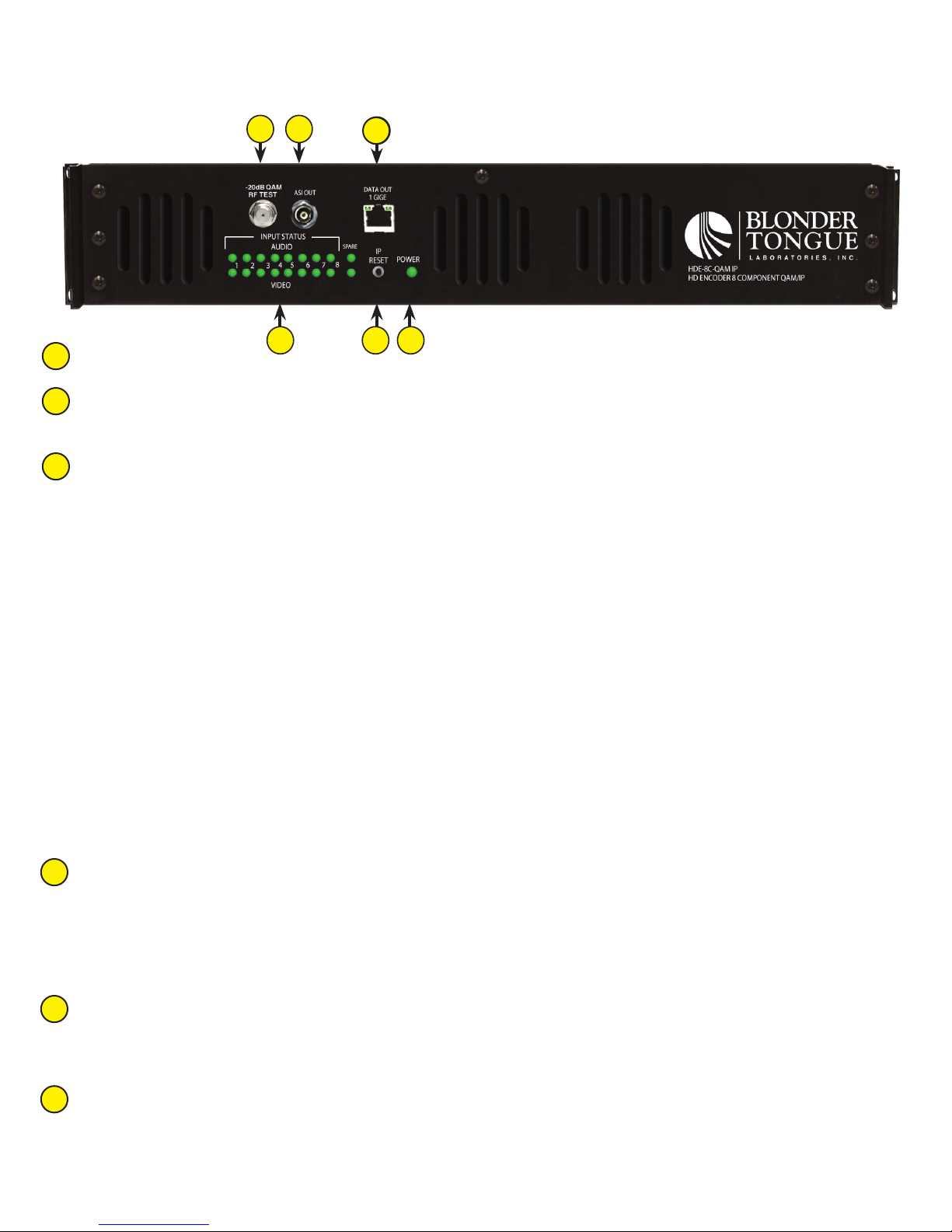
-20dB QAM RF TEST:
ASI OUT:
The “ASI OUT” BNC connector delivers any one (1) of the four (4) QAM output and is typically used as input to an
external modulator.
INPUT STATUS LEDs:
Audio LED
Green = Audio input is detected and has no errors
Red = Audio input with error
Video LED
Green = Video input is detected and has no errors
Red = Video input with error
Audio and Video LED’s in Spare Mode
When the Spare Mode is enabled, both audio and video LEDs on the spare input (#9) and its user assigned
replacement input will blink green. The LED indicators will return to their previous states when the mode is
disabled.
Audio and Video LED’s in EAS Mode
IP RESET:
IP address = 172.16.70.1
POwER:
LED is Green = AC power is detected.
3 54
1 2
1
2
3
4
5
7HDE-8C-QAM
Instruction Manual
Description:
-20dB QAM RF TEST:
ASI OUT:
The “ASI OUT” BNC connector delivers any one (1) of the four (4) QAM output and is typically used as input to an
external modulator.
INPUT STATUS LEDs:
Audio LED
Green = Audio input is detected and has no errors
Red = Audio input with error
Video LED
Green = Video input is detected and has no errors
Red = Video input with error
Audio and Video LED’s in Spare Mode
When the Spare Mode is enabled, both audio and video LEDs on the spare input (#9) and its user assigned
replacement input will blink green. The LED indicators will return to their previous states when the mode is
disabled.
Audio and Video LED’s in EAS Mode
IP RESET:
IP address = 172.16.70.1
POwER:
LED is Green = AC power is detected.
3 54
1 2
1
2
3
4
5
1
6
-20dB QAM RF TEST:
“F” connector for RF testing @ 20dB below the main QAM RF output.
ASI OUT:
The “ASI OUT” BNC connector delivers any one (1) of the four (4) QAM output and is typically used as input to an
external modulator.
INPUT STATUS LEDs:
LEDs indicate the status of audio and video of each of the eight (8) inputs plus the spare input as follows:
Audio LED
Green = Audio input is detected and has no errors
Red = Audio input with error
O=Audioinputnotdetected
Video LED
Green = Video input is detected and has no errors
Red = Video input with error
O=Videoinputnotdetected
Audio and Video LED’s in Spare Mode
When the Spare Mode is enabled, both audio and video LEDs on the spare input and its user assigned replacement input
will blink green. THe LED indicators will return to their previous states when the mode is disabled.
Audio and Video LED’s in EAS Mode
WhenEASisacvated,theAudioLEDswillchangeonatametoredstarngfromInput#1andmovingrighttoward
Input#8.ThesequenceconnuesontheVideoLEDrow,againstarngatinput#1andmovingright.AerallLEDs
haveturnedredtheyallsimultaneouslyswitchbacktogreenandthecyclebeginsagain,connuingunlEAShasbeen
deacvated.
IP RESET:
Whenpushedandheldforabout10seconds,thepowerLEDwillblinkoncetoconrmresetoperaon.Theencoder
defaults to the original address, Usernames, and Passwords as shipped from the Factory (shown below).
IP address = 172.16.70.1
Username=Admin(case-sensive)
Password=pass(case-sensive)
POWER:
LED is Green = AC power is detected.
LEDiso=indicates(i)ACpowerisnotconnected,or(ii)ACpowerisconnectedbutthepowersupplyisdefecve.
TheunitmustbesenttoBlonderTongueforrepairforcondion(ii).
DATA OUT 1 GIGE:
RJ45 connector for GigE (1000Base-T Ethernet) interface for SPTS or MPTS output streams.
OnlystacIPaddresscanbeassignedtothisinterface.Thefactorydefaultvalueis192.168.252.1.
2
3
4
5
6


