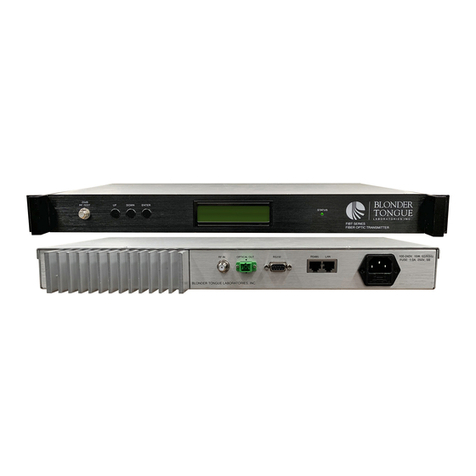
Blonder tongue FIBER Series User manual

BLONDER TONGUE LABORATORIES, INC. |ISO 9001:2015 CERTIFIED |WWW.BLONDERTONGUE.COM
Rev: 063023 P/N: 651247900A
USER MANUAL
FIBER SERIES
All Rights Reserved. All trademarks are property of their respective owners.
Specifications and Manual information subject to change without notice.
FIBT-1310 SERIES
1310nm FIBER OPTIC TRANSMITTERS
STOCK # MODEL NAME DESCRIPTION
7603 06 FIBT-1310-06 6 dBm Output, 1310 nm; Single-Mode; DFB Laser; SNMP
7603 10 FIBT-1310-10 10 dBm Output, 1310 nm; Single-Mode; DFB Laser; SNMP
7603 135 FIBT-1310-135 13.5 dBm Output, 1310 nm; Single-Mode; DFB Laser; SNMP
7603 15 FIBT-1310-15 15 dBm Output, 1310 nm; Single-Mode; DFB Laser; SNMP

2FIBT-1310 SERIES
User Manual
RETURNING PRODUCT FOR REPAIR (OR CREDIT)
A Return Material Authorization (RMA) Number is required on all products returned to Blonder Tongue,
regardless if the product is being returned for repair or credit. Before returning product, please review our
return policies or contact our service department for further information.
CROSS-REFERENCE & HYPERLINKING USAGE
This guide makes use of hyperlinks for the Table of Contents, some cross-reference linking between sections,
and external hyperlinking to web addresses. This has been done to assist the reader in nding the information
they are seeking in a much quicker way. In addition to hyperlinking, the Table of Contents also makes use of
the bookmarking feature present in the Adobe Reader application.
PRODUCT AND DOCUMENTATION UPDATES
The latest user documentation (PDF) and Firmware Updates can be obtained by visiting our website. Navigate
to the product page by entering the full Model Name in the search eld. Firmware Updates can also be directly
accessed under the “Support” section of the website. If you cannot nd your product model on the website,
please reach out to Tech Support through our support request form.
We recommend that you write the following information in the spaces provided below.
The information contained herein is subject to change without notice. Revisions may be issued to
advise of such changes and/or additions.
Correspondence regarding this publication should be addressed directly to:
Blonder Tongue Laboratories, Inc.
One Jake Brown Road
Old Bridge, NJ 08857 USA
Document Number: 651247600A
Printed in the United States of America.
All product names, trade names, or corporate names mentioned in this document are acknowledged to
be the proprietary property of the registered owners.
This product incorporates copyright protection technology that is protected by U.S. patents and other
intellectual property rights. Reverse engineering or disassembly is prohibited.
Purchase Location Name:
Purchase Location Telephone Number:
FIBT-1310 Series Serial Number(s):

3FIBT-1310 SERIES
User Manual
TABLE OF CONTENTS
SECTION 1 – GENERAL & SAFETY INSTRUCTIONS............................................................ 4
1.1 SAFETY PRECAUTIONS ...................................................................................................................................4
1.2 LASER SAFETY PROCEDURES .........................................................................................................................4
SECTION 2 – PRODUCT SUMMARY ...................................................................................... 5
2.1 PRODUCT APPLICATION & FEATURES ..............................................................................................................5
2.2 PRODUCT DESCRIPTION .................................................................................................................................6
SECTION 3 – SPECIFICATIONS .............................................................................................. 7
3.1 LINK TEST CONDITION....................................................................................................................................7
3.2 PRODUCT SPECIFICATIONS .............................................................................................................................7
3.2 PRODUCT SPECIFICATIONS (CONTINUED).........................................................................................................8
3.3 OPTICAL LINK C/N TABLE ...............................................................................................................................8
SECTION 4 – INSTALLATION & POWER-UP .......................................................................... 9
4.1 UNPACKING & PREPARATION ..........................................................................................................................9
4.2 INSTALLATION ...............................................................................................................................................9
SECTION 5 - FRONT PANEL CONFIGURATION ................................................................... 10
5.1 LCD PARAMETER FUNCTIONS ........................................................................................................................ 10
5.2 ALARM INDICATORS ......................................................................................................................................12
6.2 WEB PAGE SETUP (RECOMMENDED)............................................................................................................ 13
SECTION 6 - SYSTEM & SNMP MANAGEMENT ................................................................... 13
6.1 AGENT SETTINGS AND CONSOLE MANAGEMENT .............................................................................................13
6.3 SETTING PRIVATE IP ADDRESS ...................................................................................................................... 14
6.4 OPTICAL SETTING PAGES ...........................................................................................................................15
6.5 CONSOLE MANAGEMENT (RS232) ...............................................................................................................16
6.6 PARAMETERS IN SNMP .................................................................................................................................16
SECTION 7 – CLEANING AND MAINTENANCE .................................................................... 19
7.1 CLEANING THE UNIT(S).................................................................................................................................. 19
7. 2 CLEANING THE CONNECTOR(S) ......................................................................................................................19
7.3 CONNECTOR HANDLING................................................................................................................................. 19
SECTION 8 – TROUBLESHOOTING ...................................................................................... 20
8.1 TROUBLESHOOTING: LCD AND ALARMS..........................................................................................................20
8.2 TROUBLESHOOTING: TECHNICAL SUPPORT ....................................................................................................20
LIMITED WARRANTY ............................................................................................................. 23

4FIBT-1310 SERIES
User Manual
SECTION 1 – GENERAL & SAFETY INSTRUCTIONS
This product is designated for use in restricted locations. It is strongly advised that you always follow these safety
instructions to help ensure against injury to yourself and damage to your equipment.
åALWAYS read the product data sheet and the laser safety label before
powering the product. Note the operating wavelength, optical output power,
and safety classifications.
åIf safety goggles or other eye protection are used, be certain that the protection
is effective at the wavelength(s) emitted by the device under test BEFORE
applying power.
åALWAYS connect a fiber to the output of the device BEFORE power is applied.
Power should never be applied without an attached fiber output. If the device
has a fiber output, a connector should be attached that is connected to a
fiber. This ensures that all light is confined within the fiber waveguide, virtually
eliminating all potential hazard.
åNEVER look in the end of a fiber to see if light is coming out. NEVER! Most
fiber optic laser wavelengths (1310 nm and 1550 nm) are totally invisible to the
unaided eye and will cause permanent damage. Shorter wavelength lasers (e.g.
780 nm) are visible and are very damaging. Always use instruments, such as an
optical power meter, to verify light output.
åNEVER, NEVER, NEVER look into the end of a fiber on a power device with
1.2 LASER SAFETY PROCEDURES
ANY sort of magnifying device. This includes microscopes, eye loupes, and
magnifying glasses. This WILL cause permanent, irreversible burn on your
retina.
åALWAYS double check that power is disconnected before using such devices. If
possible, completely disconnect the unit from any power source.
åIf you have questions about laser safety procedures, please call Blonder Tongue
before powering your product.
åDo not attempt to service the unit yourself, as opening or removing covers may
expose you to dangerous voltage and will void the warranty. Refer all servicing
to authorized service personnel.
åUnplug the unit from the wall outlet and refer servicing to authorized service
personnel whenever the following occurs:
oThe power supply cord or plug is damaged;
oLiquid has been spilled, or objects have fallen into the unit;
oThe unit has been exposed to rain or water;
oThe unit has been dropped or the chassis has been damaged;
oThe unit exhibits a distinct change in performance.
1.1 SAFETY PRECAUTIONS
åThe optical emissions from the units are laser-based Class IIIb, and may present eye hazards if improperly used. NEVER USE ANY KIND OF OPTICAL INSTRUMENT
TO VIEW THE OPTICAL OUTPUT OF THE UNIT.
åAs always, be careful when working with optical fibers. Fibers can cause painful injury if they penetrate the skin.
Class 1 Laser Product IEC 60825-1: 2014
Wavelength: 1.31µm Max Output: 31mW
WARNING
INVISIBLE LASER RADIATION
AVOID DIRECT EYE EXPOSURE TO BEAM
ATTENTION
LASER RADIATION INVISIBLE EVITER
UNE EXPOSITION DIRECTE DES YEUX AU FAISCEAU
HAZARD
LEVEL 1
IEC 60825-2:2004
The STOP sign symbol is intended to alert you to the
presence of REQUIRED operating and maintenance
(servicing) instructions that if not followed, may result in
product failure or destruction.
The YIELD sign symbol is intended to alert you to the
presence of RECOMMENDED operating and maintenance
(servicing) instructions.
The LIGHTNING flash symbol is intended to alert you
to the presence of uninsulated “dangerous voltage”
within the product's enclosure that may be of sufficient
magnitude to constitute a risk of electrical shock.
TO REDUCE THE RISK OF ELECTRICAL SHOCK, DO NOT REMOVE COVER
FROM THIS UNIT.
NO USER-SERVICEABLE PARTS INSIDE. REFER SERVICING TO QUALIFIED
SERVICE PERSONNEL.
WARNING: TO PREVENT FIRE OR SHOCK HAZARD, DO NOT EXPOSE THIS
UNITTO RAIN OR MOISTURE
NOTE TO CATV SYSTEM INSTALLER
This reminder is provided to call the CATV System Installer’s attention to
Article 820-40 of the NEC that provides guidelines for proper grounding and, in
particular, species that the cable ground shall be connected to the grounding
system of the building, as close to the point of cable entry as practical.
WARNING:
Use of controls or adjustments or performance of procedures other than those specified herein may result in
hazardous radiation exposure. The optical emissions from the units are laser-based and present eye hazards.
Avoid Exposure and follow all safety precautions.

5FIBT-1310 SERIES
User Manual
SECTION 2 – PRODUCT SUMMARY
2.1 PRODUCT APPLICATION & FEATURES
APPLICATION
The FIBT-1310 (Fiber Optic Transmitter) is an ideal solution to seamlessly transport extremely high speed digital
data over single mode optical ber. The product is specically designed to transport data streams which maintain
conformance with the DOCSIS 3.1 standards and/or were generated utilizing high order quantization techniques,
such as QAM 1024, 8PSK, and COFDM.
The FIBT-1310 is built with a directly modulated DFB laser, providing low noise and high linearity performance.
The RF AGC and pre-distortion circuit ensures the optimum laser drive level for the best overall CNR, CSO, and
CTB operation. The transmitter is available in power output levels ranging from +3 dBm (2 mW) to +15 dBm (31
mW) to satisfy various system topologies and supports an increased band-edge to 1218 MHz for DOCSIS 3.1
applications.
Laser output power, unit temperature, and RF input level are accurately monitored by a built-in microprocessor
and shown on the front panel LCD display, in addition to the unit function messages. Remote status monitoring
is provided through SNMP network management.
KEY FEATURES
▶47 to 1218 MHz RF bandwidth for DOCSIS 3.1 compatibility
▶High performance and low power consumption GaAs technology
▶1310nm DFB laser in 5 output power levels (3, 6, 10, 12, 15 dBm)
▶RF AGC for optimum laser performance
▶LCD front panel status display with built-in microprocessor
▶SNMP network management for remote monitoring
▶ETL certied
FUNCTION BLOCK DIAGRAM:
Predistortion Board
ATC APCRF Power DetectAGC/MGC
Network
Management Micro Processor LCD Display Switching
Power Supply
Preamplifier
Power
Amplifier
-20dB Test
Optical
Output
DFB
Laser
AC Input
RF Input
Attenuation

6FIBT-1310 SERIES
User Manual
FRONT PANEL:
-20dB RF Test: “F” connector for RF testing @ 20dB lower than the actual RF drive level to the laser.
(MOD Level Setting)
UP: scrolls the LCD display UP, or increases the setting value. See Section 5.1 for more information.
DOWN: scrolls the LCD display DOWN, or decreases the setting value. See Section 5.1 for more information.
ENTER: MGC/AGC mode and MGC Attenuation select. See Sec tion 5.1 for more information.
LCD MONITOR: Displays status parameters, product model, serial number and other information about the
transmitter. See Section 5.1 for parameters.
Status LED: Indicates the status of the unit for troubleshooting, as follows:
▶OFF = indicates the unit is not correctly connected or receiving power.
▶GREEN = Normal Operation; indicates the unit is operating normally and is running without errors.
▶AMBER = The RF Input Level is too low. See Section 5.2 for more information.
▶
RED = Warning; indicates that one or more errors have been detected. Check the LCD message to
troubleshoot the problem. See Section 5.2 for more information.
A
B
C
D
E
F
BACK PANEL:
Case Grounding Nut: Provided for optionally connecting the transmitter to the ground.
RF IN: “F” connector (75Ω). RF input signal level range should be between 15 dBmV and 25 dBmV for AGC
operation.
G
H
2.2 PRODUCT DESCRIPTION
A B C ED F
GH I KJ L M
CAUTION: There are invisible laser emissions from Fiber output when the laser is active! It would be dangerous
to point this port toward the human body, especially eyes, when equipment has power running through it!

7FIBT-1310 SERIES
User Manual
2.2 PRODUCT DESCRIPTION (CONTINUED)
OPTICAL OUT: Optical signal output port, SC/APC.
RS232: this standard network management port is used for connecting equipment with RS-232 port in
network management server. See Section 6 for more information.
LAN network management port: Use for connecting transmitter with Ethernet-basing SNMP network
management server. Default IP address is “10.10.10.254“
WAN network management port: Use for connecting transmitter with Ethernet-basing SNMP network
management server. See Section 6 for more information. Default setting is Static IP.
INPUT POWER: IEC 14 power inlet plug - rated 100/240 VAC, 15W, 50/60 Hz; equipped with Slo-Blo, 1.0A,
250 V fuse.
I
J
K
L
M
3.1 LINK TEST CONDITION
Test link consists of FIBT transmitter, 10Km single mode ber, optical attenuator and FTTB Blonder Tongue
optical receiver. Input RF channels are 77 CW carriers (50~550 MHz) and digital channels (550 MHz~1218 MHz,
RF level 10 dB lower) at -1 dBm optical input.
SECTION 3 – SPECIFICATIONS
3.2 PRODUCT SPECIFICATIONS
OPTICAL
Operating
Wavelength
1310 nm ± 20 nm
Optical Power
Output
3 dBm (2 mW), 6 dBm (4 mW), 10 dBm
(10 mW), 12 dBm (16 mW) & 15 dBm
(31 mW)
Laser Type
Class 1 DFB (directly modulated; Hazard
Level 1). The 3 dBm model is built
with an uncooled laser. The 6 & 10
dBm models are available with either
a cooled or uncooled laser. The 12 &
15 dBm models employ only cooled
lasers.
Beam Divergence
Angle:
8˚ max
Connector
SC/APC (a FC/APC connection adapter is
sold separately for applications requiring it)
Model: FC Adapter;
Stock# 7607
Description:
SC/APC Male to FC/APC Female
LINK PERFORMANCE*
CNR
≥ 51 dB (see table below)
CSO
< -62 dBc
Operating Humidity
< -65 dBc
* 77 CW carriers (50-550 MHz) and digital channels (550 - 1218 MHz, RF
level 10 dB lower) at -1 dBm optical input into a Blonder Tongue FTTB receiver.
RF
Connector
“F” Female
Frequency Range
47-1218 MHz
Input Level
15-25 dBmV
Flatness
±1.0 dB
Impedance
75 Ω
Return Loss
≥ 16 dB
AGC Range
0-15 dB
MGC Range
0-15 dB

8FIBT-1310 SERIES
User Manual
ALARMS & MONITORING
Local Monitoring
1x Status Tri-Color LED
(Red, Green, Amber)
Local Control
Display: LCD
Navigation: 3 Buttons for LCD
(Up/Down/Enter)
Remote Monitor/Control
SNMP: RJ45 Connector @
100/1G
GENERAL
Dimensions
(W x H x D)
19.0 x 1.75 x 15.31 in
(483 x 44 x 369 mm)
Weight
7.0 lbs (3.18 kg)
POWER
Power Supply
100-240 VAC 50/60 Hz
Power Consumption
15 W
ENVIRONMENTAL
Operating
Temperature Range
32 to 113 °F (0 to 45 °C)
Relative Humidity
0 to 95%, non-condensing
3.2 PRODUCT SPECIFICATIONS (CONTINUED)
3.3 OPTICAL LINK C/N TABLE
OPTICAL LOSS (dB)6 7 8 9 10 11 12 13 14 15 16 17
FIBT-1310-06 52.0 51.0 50.1 49.1 48.1
FIBT-1310-10 51.9 51.0 50.1 49.1 48.2
FIBT-1310-13.5 52.3 51.3 50.4 49.5
FIBT-1310-15 51.9 50.9 49.9

9FIBT-1310 SERIES
User Manual
SECTION 4 – INSTALLATION & POWER-UP
4.2 INSTALLATION
The FIBT-1310 Series transmitters are designed to be installed into any standard 1RU 19" rack. Verify that the
power source to the rack is turned OFF before installing the unit into the rack.
Mount and secure the unit’s front panel to the rack by inserting four (4) machine screws, with cup washers,
through the four (4) mounting holes in the front panel. Ground the case immediately afterward.
Check input voltage using a digital multimeter in accordance with power requirement. After you are satised
with the results, plug in the power cable.
NOTE: When the unit is rst plugged in, it will briey beep one time. This indicates that the transmitter
has successfully initialized.
Check the message on the LCD and the status of the front panel LED indicator. Push the UP and DOWN
buttons to check each parameter, insuring that the transmitter is operating normally.
NOTE: If there is no RF input, the status LED will be a steady orange and the LCD will display “INPUT
RF IS LOW” at Section 5.1, .
Connect standard ber test cable to the transmitter's optical output. Measure the optical output power and
conrm that it is approximately the same as the value displayed on the LCD.
When measuring the optical power, make sure that the optical power meter is set for the 1310nm
wavelength and that the ber test connector is clean.
Measure the input RF level with an RF signal meter or a spectrum analyzer, making sure the RF signal is in the
AGC range of the transmitter. At this time, you can connect the RF signals to the RF IN port of the FIBT. The
front panel Status LED should be Green and the LCD will display the RF input level as “INPUT RF=XXdBmV”.
Re-measure the optical output power to ensure that it is normal. Remove the standard ber test jumper and
optical power meter, then connect the FIBT to the network.
You will need the following tools and supplies for installation:
▶An optical power meter
▶A digital multimeter
▶An RF signal meter or spectrum analyzer
▶A standard ber test jumper
▶Denatured or 99% pure isopropyl alcohol and lint-free ber optic cleaning wipes.
1
2
3
4
5
6
6
4.1 UNPACKING & PREPARATION
You will nd the following items in the box:
▶FIBT-1310 Series 1RU transmitter (QTY=1)
▶Power Cord with IEC C13 line socket and 3-pin Type B NEMA 5 plug (QTY=1)
CAUTION: If any of the equipment appears to have been damaged, do NOT connect it to a power source.
This will only cause additional damage to the unit. Contact Technical Support for further instructions.

10 FIBT-1310 SERIES
User Manual
SECTION 5 - FRONT PANEL CONFIGURATION
Start Screen: Upon power-up, “Blonder Tongue” will
appear on the LCD, indicating the top of the LCD menu.
The following screens are in descending order and are
accessed by pressing the DOWN button.
1
AGC Status: AGC/MGC (Automatic/Manual Gain Control):
Pressing ENTER will toggle between AGC and MGC mode.
The menus below will display parameters and allow changes
based on the gain control mode selected.
2
S/N: displays the serial number of the unit.
3
5.1 LCD PARAMETER FUNCTIONS
You must complete the steps described in Section 4 before proceeding. Where UP, DOWN, or ENTER is mentioned,
use the associated buttons on the front panel.
Note: The LCD backlighting is activated for approximately 5 seconds after pressing the UP, DOWN, or ENTER
buttons.
MOD Level=XXdBmV:
If “AGC” is selected in , the LCD displays the modulation
level being applied to the laser. This menu also allows the
user to change the modulation level in 1dB increments
over a range of 30 to 45 dBmV.
To change the value, press ENTER. When the LCD displays “Please Install...” the user can scroll through
the range using the UP/DOWN buttons. When the desired value has been reached, press the ENTER button
to apply the change.
If “MGC” is selected in , the LCD displays the modulation level being applied to the laser and does not
allow changes.
4
2
2
AGC/MGC ATTEN=XXdB:
If “AGC” is selected in , the LCD displays the AGC
attenuation. This is controlled internally and is not user-
adjustable.
If “MGC” is selected in , the LCD displays the MGC attenuation. This is user-adjustable in 1dB increments
over a range of 0 to 15 dB.
NOTE: Changing this attenuator will also change the MOD level described in . Example: A 2dB increase
MGC attenuation will automatically apply a 2dB decrease in MOD level.
The user may adjust the MOD Level by 1 or 2 dB to suit their system. The higher the MOD level, the better the
CNR and the worse the CSO/CTB. The lower the MOD level, the worse the CNR and the better the CSO/CTB.
5
2
2
4

11FIBT-1310 SERIES
User Manual
NOTE: Factory MOD Level is set for optimum CSO/CTB/CNR. It is recommended to record this setting prior to changing
MOD Level.
5.1 LCD PARAMETER FUNCTIONS (CONTINUED)
Warning: On some FIBT models, selecting too low an attenuator value can result in excessive MOD level. When
this happens, the status LED will ash red and an audible alarm will sound until a safe level is established.
Also, the MOD Level screen will display “MOD Level is High”.
Number of Input Carriers
110 77 40
Recommended RF Input
Level
17dBmV 20dBmV 25dBmV
INPUT RF: indicates the RF Input Level in dBmV. Note: the
internal power detector is calibrated for 77 CW carriers,
and accuracy may vary depending on users frequency plan.
The following table is a guideline for the number of input
carriers vs. recommended RF input levels:
6
Bias: indicates the bias current of the laser
7
TEMP: indicates the internal temperature of the laser
in degrees Celsius (°C).
8
Power: indicates the optical output power in milliwatts
(mW).
9
FIBT-1310-XX: indicates the model name, with “XX”
indicating the output power level in dBm.
10
To change the value, press ENTER. When the LCD displays “Please Install...” the user can scroll through
the range using the UP/DOWN buttons. When the desired value has been reached, press the ENTER
button to apply the change.

12 FIBT-1310 SERIES
User Manual
5.2 ALARM INDICATORS
The following chart details system warnings for troubleshooting purposes.
ERROR
CONDITION MODE LCD MESSAGE
D I S P L AY STATUS LED AUDIBLE ALARM
RF Input Level
Too High
ACG MOD Level =
XXdBmV
INPUT RF = XXdBmV
Flashes RED at
≈1sec Intervals
Beeper sounds in-sync
with status LED
MCG MOD Level Is High
INPUT RF = XXdBmV
RF Input is
Too Low
ACG MOD Level =
XXdBmV
INPUT RF IS LOW
Orange
(Red+Green)
Steady On
None
MCG
Excessive MOD
Level
MCG MOD Level Is High Flashes RED at
≈1sec Intervals
Beeper sounds in-sync
with status LED

13FIBT-1310 SERIES
User Manual
SECTION 6 - SYSTEM & SNMP MANAGEMENT
Simple Network Management Protocol (SNMP) is an Internet-standard protocol for collecting and organizing
information about managed devices on IP networks and for modifying that information to change device behavior.
Devices that typically support SNMP include routers, switches, servers, workstations, printers, modem racks and
more.
When the built-in RJ-45 Ethernet adapter is connected to an IP network, operators can remotely access device
settings via Telnet and SNMP for managing and monitoring the FIBT. This can be handled by a command line
interface (CLI). A MIB Browser can be used to access and read the settings and parameters. Readily available
SNMP software can provide a graphical user interface to performing these functions.
FIBT uses SNMP v2 and can be accessed through either the LAN adapter or the WAN adapter.
For best security practices, we recommend not connecting to the SNMP connectors if the operator is not going
to use SNMP to manage the device.
6.1 AGENT SETTINGS AND CONSOLE MANAGEMENT
Before using the SNMP features in FIBT, operators need to ensure it can be accessed. This may require adjusting
the IP network settings.
ADJUSTING THE DEFAULT IP NETWORK AND SNMP AGENT SETTINGS
The FIBT transmitter supports Telnet and web page management. When FIBT is connected with a computer
via RJ-45 (RS485), the computer IP address should be next to “192.168.1.20”. After both units are successfully
linked, the user can enter the IP address 192.168.1.20 into a web brower, such as Chrome.
After successful connection, the default user name and password are required.
Username = admin (case-sensitive)
Password = admin (case-sensitive)
6.2 WEB PAGE SETUP (RECOMMENDED)
1] Enter 192.168.1.20 in the browser address bar.
2] The default user name and password are admin. The successful landing page will have the following Blonder
Tongue header at the top.

14 FIBT-1310 SERIES
User Manual
6.3 SETTING PRIVATE IP ADDRESS
The user can change the FIBT IP address of the LAN network port on the following page:
The user can also change the FIBT IP address of the WAN network port in the same Internet Settings section,
within the following page:

15FIBT-1310 SERIES
User Manual
6.4 OPTICAL SETTING PAGES
Under “Optical setting”, the “Basic Info” page displays the basic parameters of the optical transmitter device
(OTD), including LD parameters, RF parameters, device model, SN, and working mode. The parameters must be
consistent with those displayed on the front panel of the device. The information cannot be modied.
Parameter Settings and SNMP Threshold Settings are the pages through which the manufacturer sets the
parameters for proper operation for the optical signal of the optical transmitter and the SNMP NMS, unless the
user is allowed not to modify these parameters.

16 FIBT-1310 SERIES
User Manual
6.6 PARAMETERS IN SNMP
SNMP software with transmitter MIB can read the parameters from FIBT optical transmitter. The following output
is an example of parameters after loading transmitter MIB.
1
1
1
1
1
1
1
6.5 CONSOLE MANAGEMENT (RS232)
The FIBT transmitter provides console management with RS232 port. When the machine is powered on, the
RS232 port will print out some rmware module loading information and network default information, which can
be used as reference for machine development or maintenance. The RS232 Interface is:
NOTICE:
▶Open the Hyper Terminal of the computer and set the COM port parameter as above.
ITEM VALUE
Interface RS232
Type DB9-Female
Rate 57600bps
Data Bit 8
Stop Bit 1
Parity None
Data Flow Control None

17FIBT-1310 SERIES
User Manual
6.6 PARAMETERS IN SNMP (CONTINUED)
1
1
1
1
1
1
1
1
1
1
1
1
1
1
1
1

18 FIBT-1310 SERIES
User Manual
1
1
1
1
1
1
1
1
1
1
6.6 PARAMETERS IN SNMP (CONTINUED)

19FIBT-1310 SERIES
User Manual
SECTION 7 – CLEANING AND MAINTENANCE
7.1 CLEANING THE UNIT(S)
If the units need to be cleaned, avoid the use of all solvents and use low-pressure clean air to remove loose
dirt. Use low-pressure clean air to clear the connectors of any debris. Dirty or scratched connector end faces
will greatly reduce the unit’s performance. Foam-tipped swabs may be saturated with denatured alcohol* and
inserted into the optical port for cleaning. DO NOT INSERT A DRY SWAB INTO THE OPTICAL PORT AS THIS MAY
DAMAGE THE FIBER END FACE. Many ber optic installations experience degraded performance due to dirty
optical connector end faces. The following procedure should be used to properly clean the optical connector end
faces.
DIRECTIONS FOR CLEANING:
1) Fold the ssue twice so it is four layers thick.
2) Saturate the ssue with alcohol.
3) First clean the sides of the connector ferrule. Place the connector ferrule in the ssue, and apply pressure to the sides
of the ferrule. Rotate the ferrule several mes to remove all contaminaon from the ferrule sides.
4) Now move to a clean part of the ssue. Be sure it is sll saturated with alcohol, and it is sll four layers thick. Put the
ssue against the end of the connector ferrule. Put your ngernail against the ssue so that it is directly over the ferrule.
Now gently scrape the end of the connector unl it squeaks. It will sound like a crystal glass that has been rubbed when
it is wet.
5) Use the magnier to verify the quality of the cleaning. If it isn’t completely clean repeat the steps with a clean ssue.
6) Mate the connector immediately! Don’t let the connector lie around and collect dust before mang.
7) Air can be used to remove lint or loose dust from the port of a transmier or receiver to be mated with the connector.
Never insert any liquid into the ports.
7.2 CLEANING THE CONNECTOR(S)
REQUIRED CLEANING EQUIPMENT:
▶Kimwipes®or any lens-grade, lint-free tissue. The type sold for eyeglasses work quite well.
▶Denatured Alcohol.
NOTE: Use only industrial grade 99% pure isopropyl alcohol. Commercially available isopropyl alcohol is for
medicinal use and is diluted with water and a light mineral oil. Industrial grade isopropyl alcohol should be
used exclusively.
▶30X Magnier.
▶Canned Dry Air.
7.3 CONNECTOR HANDLING
▶NEVER TOUCH THE FIBER END FACE OF THE CONNECTOR.
▶Connectors not in use should be covered over the ferrule by a plastic dust cap. It is important to note that the
inside of the ferrule dust caps contains a sticky gelatinous residue that is the by-product of the making of the
dust cap. This residue will remain on the ferrule end after the cap is removed. Therefore it is critical that the
ferrule end be cleaned thoroughly BEFORE it is mated to the intended unit.

20 FIBT-1310 SERIES
User Manual
SECTION 8 – TROUBLESHOOTING
ERROR CONDITION LCD MESSAGE DISPLAY AUDIBLE ALARM
No LCD or LED display
after turning on the
p o w e r.
No input power or a problem
with the internal switching
power supply.
Check input AC voltage to the
power supply (100-240 VAC), if the
voltage is normal, usually the
cause is the internal switching
power supply. Contact Technical
Support.
After turning on power,
LCD monitor and LED
normal, but optical
output power low.
Check jumper quality Swap to a good test jumper
Contaminated optical active
connector or adapter
Clean contaminated ber active
connector adapter (Section 7)
Damaged ceramic ferrule in
adapter
Swap the damaged adapter
After connecting to
network, all carrier
channels have obvious
noise point.
Low received optical power,
causing poor C/N.
Clean ber active connector or
adapter (Section 7)
RF input level too low for
sufcient laser modulation
Check RF input levels to
transmitter. (15-25 dBmV)
System link path C/N too
low.
Check link loss
Back-reection from bad or
dirty optical connectors
Use only angled (SC/APC) optical
connectors or fusion splice where
necessary.
After connecting to
network, only some
carrier channels have a
degraded SNR
Some channels SNR too low Check the individual channel
signal C/N or SNR
Check the atness of the RF input
After connecting to the
network, some carrier
channels have obvious
ripple, beats, lines, or
distortions.
Optical input power to
receiver is too high
Check input power at optical
receiver and pad, if necessary
RF modulation is too high. Check the optical transmitter
modulation level parameter and
re-adjust if too high.
RF input drive to
transmitter is too high.
Make sure the RF input level is
within the range (15-25 dBmV)
8.2 TROUBLESHOOTING: TECHNICAL SUPPORT
For any additional technical support issues, please send more information to us about your issue via our website
at www.blondertongue.com/support/ or call us toll-free at 1-800-523-6049 between the hours of 8:00 AM and
5:00 PM (EST, UTC -5).
8.1 TROUBLESHOOTING: LCD AND ALARMS
This manual suits for next models
9
Table of contents
Other Blonder tongue Transmitter manuals