Safety Instructions
This product is designated for use in restricted locaons. It is strongly advised that you ALWAYS follow
these safety instrucons to help ensure against injury to yourself and damage to your equipment.
Safety Precauons
åThe optical emissions from the units are laser-based Class IIIb, and may present eye hazards if improperly used. NEVER USE ANY KIND OF OPTICAL INSTRUMENT
TO VIEW THE OPTICAL OUTPUT OF THE UNIT.
åAs always, be careful when working with optical fibers. Fibers can cause painful injury if they penetrate the skin.
TO REDUCE THE RISK OF ELECT RIC AL SHOC K, DO NOT REMOVE COVER FROM THIS
UNIT. NO USER-SERVICEABLE PARTS INSIDE. REFER SERVICING TO QUALIFIED
SERVICE PERSONNEL.
The YIELD sign symbol is intended to alert you to the presence
of RECOMMENDED operating and maintenance (servicing)
instructions. NOTE TO CATV SYSTEM INSTALLER
This reminder is provided to call the CATV System Installer’s aenon to Arcle
820-40 of the NEC that provides guidelines for proper grounding and, in parcular,
species that the cable ground shall be connected to the grounding system of the
building, as close to the point of cable entry as praccal.
WARNING: TO PREVENT FIRE OR SHOCK HAZARD, DO NOT EXPOSE THIS UNIT TO
RAIN OR MOISTURE
P/N: 651249400B | 082019
Blonder Tongue is ISO 9001:2015 Certied
One Jake Brown Road
Old Bridge, NJ 08857-1000 USA
732-679-4000 • Fax 732-679-4353
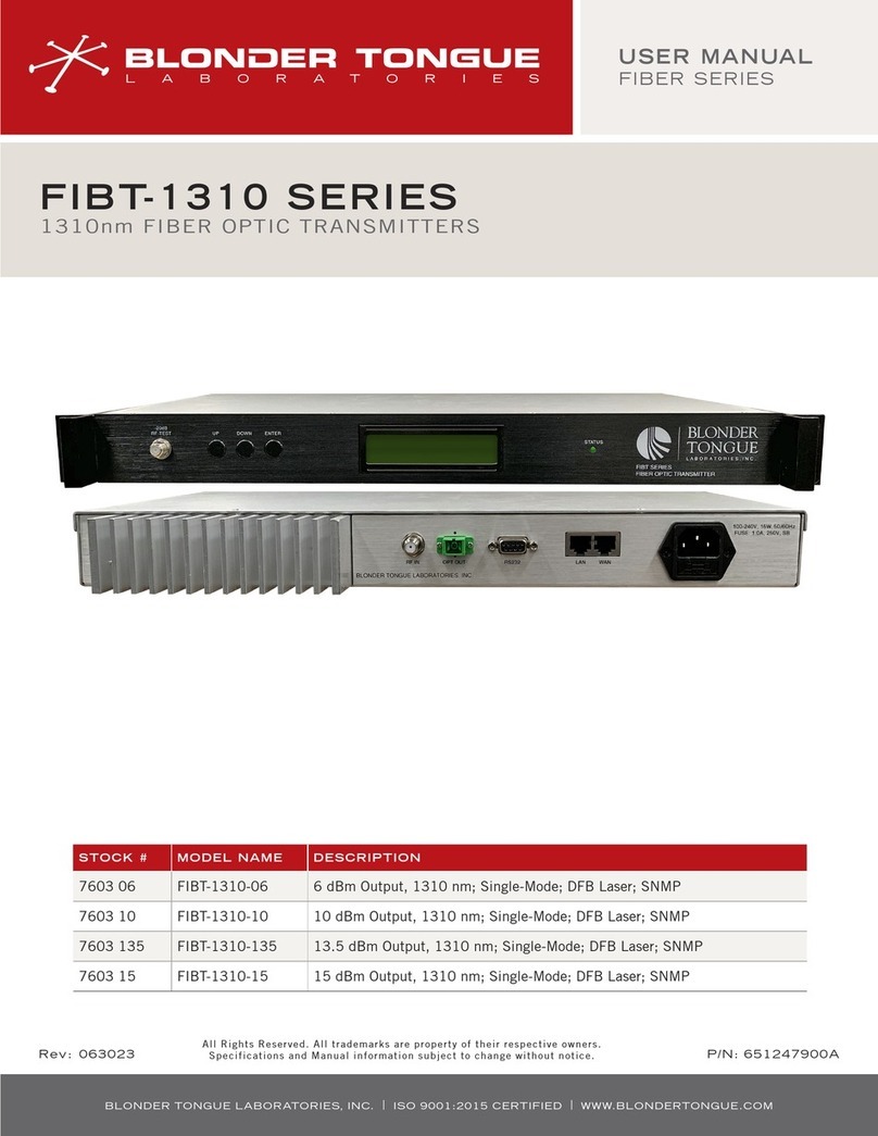
FIBT-1310 Series
1310nm Fiber Optic Transmitters
Stock No. 7603 Series
Laser Safety Procedures
åALWAYS read the product data sheet and the laser safety label before
powering the product. Note the operating wavelength, optical output power,
and safety classifications.
åIf safety goggles or other eye protection are used, be certain that the
protection is effective at the wavelength(s) emitted by the device under test
BEFORE applying power.
åALWAYS connect a fiber to the output of the device BEFORE power is applied.
Power should never be applied without an attached fiber output. If the device
has a fiber output, a connector should be attached that is connected to a
fiber. This ensures that all light is confined within the fiber waveguide, virtually
eliminating all potential hazard.
åNEVER look in the end of a fiber to see if light is coming out. NEVER! Most
fiber optic laser wavelengths (1310 nm and 1550 nm) are totally invisible to
the unaided eye and will cause permanent damage. Shorter wavelength lasers
(e.g. 780 nm) are visible and are very damaging. Always use instruments, such
as an optical power meter, to verify light output.
åNEVER, NEVER, NEVER look into the end of a fiber on a power device with
ANY sort of magnifying device. This includes microscopes, eye loupes, and
magnifying glasses. This WILL cause permanent, irreversible burn on your
retina.
åALWAYS double check that power is disconnected before using such devices. If
possible, completely disconnect the unit from any power source.
åIf you have questions about laser safety procedures, please call Blonder
Tongue before powering your product.
åDo not attempt to service the unit yourself, as opening or removing covers
may expose you to dangerous voltage and will void the warranty. Refer all
servicing to authorized service personnel.
åUnplug the unit from the wall outlet and refer servicing to authorized service
personnel whenever the following occurs:
oThe power supply cord or plug is damaged;
oLiquid has been spilled, or objects have fallen into the unit;
oThe unit has been exposed to rain or water;
oThe unit has been dropped or the chassis has been damaged;
oThe unit exhibits a distinct change in performance.
WARNING: Use of controls or adjustments or performance of procedures other than those specied
herein may result in hazardous radiaon exposure. The opcal emissions from the units are laser-based
and present eye hazards. Avoid Exposure and follow all safety precauons.
Class 1 Laser Product IEC 60825-1: 2014
Wavelength: 1.31µm Max Output: 31mW
WARNING
INVISIBLE LASER RADIATION
AVOID DIRECT EYE EXPOSURE TO BEAM
ATTENTION
LASER RADIATION INVISIBLE EVITER
UNE EXPOSITION DIRECTE DES YEUX AU FAISCEAU
HAZARD
LEVEL 1
IEC 60825-2:2004


