Radionode PT100 User manual

User Manual
PT100 Temp Sensor Transmitter
UA13
Keep this document nearby so that it may be referred to when needed.2021 | Rev. 1.03

02
Introduction Monitoring from your Computer Monitoring from your Smartphone Troubleshooting Customer Service InformationAbout this Manual
CONTENTS
About this Manual 03
Intellectual Property Rights 03
Notational Conventions 03
Introduction 04
Exteria 05
Accessories 06
Specifications 06
Connecting External Sensor 07
3-wired PT100 07
Monitoring from your Computer 08
Installing Software 08
Connecting Sensor to Tapaculo Lite 08
Starting Tapaculo Lite 09
Monitoring from your Smartphone 11
Installing Tapaculo Mobile 11
Starting Tapaculo Mobile 11
Customer Service Information 13
Manufacturer Contact Information 13
Warranty 13
Limit of Liability 13
Certifications 14
Order List 15
UA Sensor 15
Accessories 16

03
Introduction Monitoring from your Computer Monitoring from your Smartphone Troubleshooting Customer Service Information
About
this
Manual
This document contains instructions for usage and installation of
the RADIONODE®UA13. Product specifications and certain features
herein may be subject to change without prior notice. Figures used
in this manual are for explanatory purposes only, and may differ
from your system depending on installation conditions. Software
screenshots may change after software updates.
Intellectual
Property
Rights
© 2021 DEKIST Co., Ltd.
All contents and figures herein are property of DEKIST Co., Ltd.
Reproduction or redistribution of all or part of this document in any
way is not permitted without prior consent from DEKIST.
Notational
Conventions
Failure to follow instructions marked with "Warning" may
result in slight injury to the user.
Failure to follow instructions marked with "Caution" may
result in equipment damage or malfunction.
Additional helpful information is marked with "Note".
About this Manual

04
Monitoring from your Computer Monitoring from your Smartphone Troubleshooting Customer Service InformationAbout this Manual
Introduction
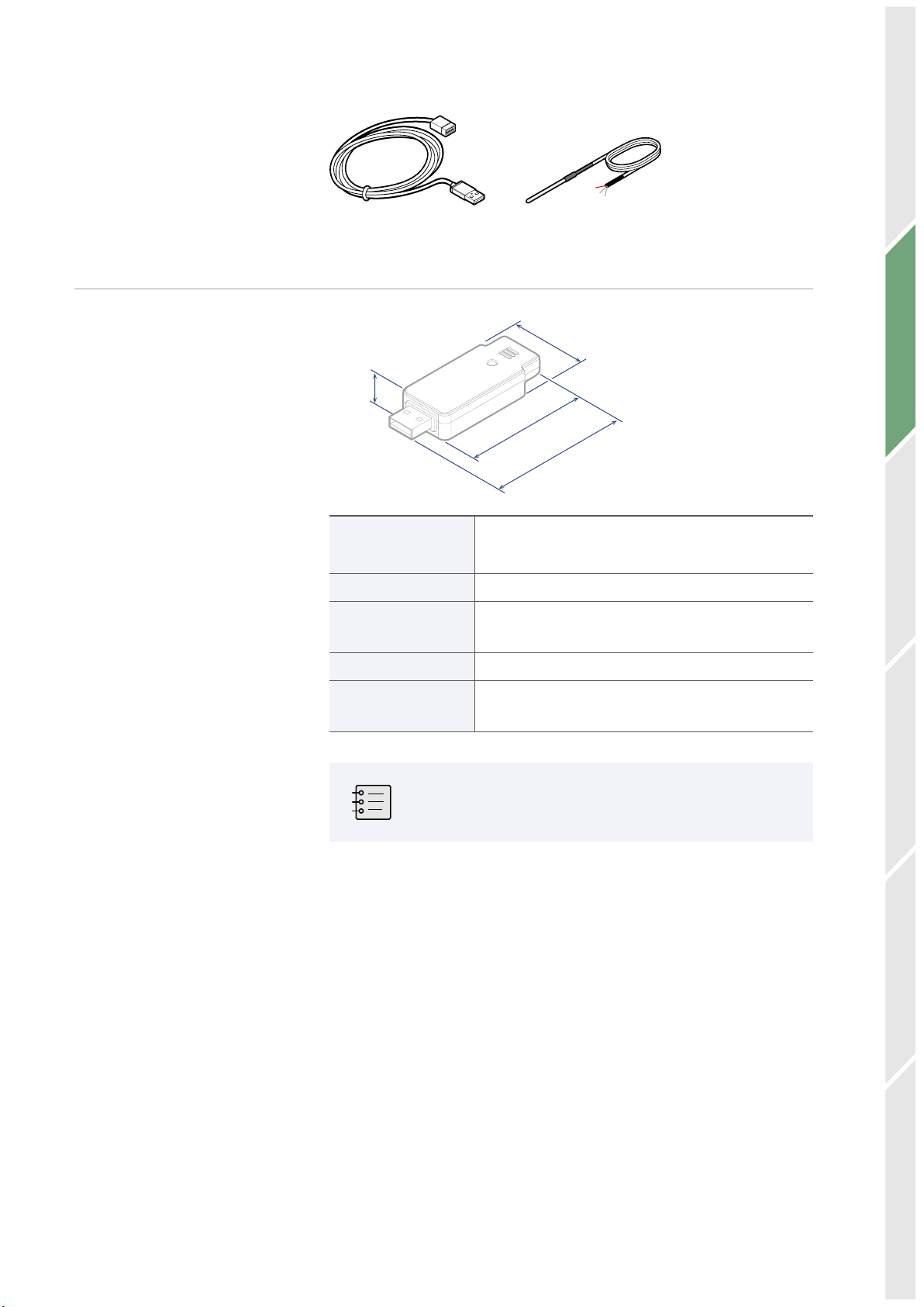
UA13 is a sensor that measures the temperature with a PT100.
Measurements are made by one of two methods:
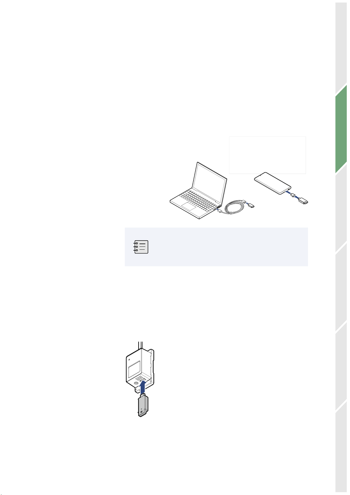
●Connect the UA13 sensor to your computer's USB port to use
the Tapaculo®Lite program.
●Connect the UA13 sensor to your smartphone via the USB
gender to use the Tapaculo®Mobile app.
5BQBDVMPm.PCJMF5BQBDVMPm-JUF
Once power is supplied through the USB port, the
sensor will commence initialization. Initialization takes
approximately 5 minutes to complete. Measurements
may not be accurate until initialization is complete.
Radionode365, the cloud-based remote surveillance service provided
RADIONODE, is available for UA13 users with a RN17x WC series
data transmitter. For information on how to install and use RN17x
WC, see the information provided on the web page below:
https://help.radionode365.com/article-categories/https://help.radionode365.com/article-categories/
RN17x WC-helpRN17x WC-help
Introduction

05
Monitoring from your Computer Monitoring from your Smartphone Troubleshooting Customer Service InformationAbout this Manual Introduction
Exteria
1 1
2
4
5
3
"
#
#
❶ USB 2.0
❹ Screw for terminal
❷ LED
❺ PT100 input terminal
❸ Screw Hole

06
Monitoring from your Computer Monitoring from your Smartphone Troubleshooting Customer Service InformationAbout this Manual
Accessories The UA13 comes with the following accessories:
USB Extension Cable
Specifications
25 mm
68.5 mm
66.2 mm
15 mm
PT100 m.range -200 ~ 300 °C (±0.625°C)
*Bundle Sensor m.range : -200 ~ 200°C
USB Port USB 2.0 Type A Plug
Power
consumption 5 V, max 50 mW
Size 68.5 × 25 × 15 mm
Operating
conditions -20~80°C, 5 〜95% RH (noncondensable)
Note that the performance of the external temperature
sensor separately may differ from when it is connected
to the Data Logger.
Introduction
PT100 (1EA)

07
Introduction Monitoring from your Computer Monitoring from your Smartphone Troubleshooting Customer Service InformationAbout this Manual
Connecting External Sensor
3-wired
PT100
"
#
#
1. Turn over UA13, connect external sensor cable from left to right
2. Loose bolt on connector for connecting external sensor cable
3. Red is +, White is - that connect as a picture
●The UA13 supports 2-wire PT100 temperature sensor.
●The UA13 can measure up to 1CH

08
Introduction Monitoring from your Smartphone Troubleshooting Customer Service InformationAbout this Manual Monitoring from your Computer
Monitoring from your Computer
This chapter outlines how to use Tapaculo Lite. For more information
on Tapaculo Lite, see the information provided on the web page
below:
https://help.radionode365.com/article-categories/https://help.radionode365.com/article-categories/
tapaculo-litetapaculo-lite
Installing
Software
To view sensor measurements on your computer, download and
install the following software package from the RADIONODE website
at www.radionode365.comwww.radionode365.com.
●Tapaculo Lite program (Windows or Mac version)
●USB drivers for Windows for UA products
Connecting
Sensor to
Tapaculo
Lite
The sensor can be connected to Tapaculo Lite via one of the
following methods:
●Insert the sensor into an available USB port on your computer.
●Insert the sensor into an available port on the USB hub that is
connected to your computer.

09
Introduction Monitoring from your Smartphone Troubleshooting Customer Service InformationAbout this Manual Monitoring from your Computer
Starting
Tapaculo
Lite
A new project must be created first before combining Tapaculo Lite
and the sensor. A project may include multiple sensors. Refer to the
following procedure when using Tapaculo Lite:
A project is a file that stores and manages sensor data.
1. Click Create Project and enter a file name. The new file will contain
sensor information.
2. Searched sensors appear in the left panel. Select a dashboard and
sensor, then click Add Device. The sensor will be added to the
dashboard.

10
Introduction Monitoring from your Smartphone Troubleshooting Customer Service InformationAbout this Manual Monitoring from your Computer
3. Click Time Interval and select the measurement interval.
4. Click OK Create Project at the bottom of the menu. The Dashboard
menu will open and display measurements of sensors registered
in the project, and sensor indicators will blink.
5. Click REC at the lower-left corner to start logging data. The REC
button will change to STOP.
6. To exit the program, click STOP. You cannot exit the program until
data logging is stopped.

11
Introduction Monitoring from your Computer Troubleshooting Customer Service InformationAbout this Manual
Monitoring from your Smartphone
This chapter outlines how to use Tapaculo Mobile. For more
information on Tapaculo Mobile, see the information provided on the
web page below:
https://help.radionode365.com/article-categories/https://help.radionode365.com/article-categories/
tpm-manualtpm-manual
Installing
Tapaculo
Mobile
Search for "Tapaculo" on Google Play, or click the link below to install
Tapaculo Mobile app on your Android smartphone.
https://play.google.com/store/apps/details?id=com.https://play.google.com/store/apps/details?id=com.
dekist.mobiledekist.mobile
Tapaculo Mobile does not have an iOS version.
Starting
Tapaculo
Mobile
Refer to the following when using Tapaculo Mobile:
1. Connect the sensor to your smartphone using the USB gender.
2. Tapaculo Mobile will open. Tap START to start logging data.
Monitoring from your Smartphone

12
Introduction Monitoring from your Computer Troubleshooting Customer Service InformationAbout this Manual
3. Swipe right to change sensor settings.
4. Swipe left to view the measurement chart.
5. Tap STORAGE to share your measurement history with others.
Measurement history is saved as a CSV file.
Date measured/tVOC measurement/carbon dioxide equivalent
(or absolute humidity) measurement
Monitoring from your Smartphone

13
Introduction Monitoring from your Computer Monitoring from your Smartphone TroubleshootingAbout this Manual Customer Service Information
Customer Service Information
Manufacturer
Contact
Information
DEKIST Co., Ltd. provides repair service and replacement parts for
RADIONODE products. To request customer service, contact us via
one of the following methods.
●Tel: +(82) 1566-4359
●Fax: (+82) 31-8039-4400
●E-mail: [email protected]
Warranty Repairs are provided free of charge for product failure under normal
operating conditions within one year of the product installation date.
Limit of
Liability
Warranty repairs are not provided in the event of:
●Failure caused by unapproved installation methods;
●Failure caused by user negligence;
●Failure caused after alteration, disassembly, or repair of the
product by a person unauthorized by DEKIST;
●Failure caused by corrosion, falling, submersion, or other
improper storage methods;
●Failure caused by natural disaster or other unforeseen
circumstances, such as storms, floods, earthquakes, lightning, or
abnormal voltage;
●Service requested for actions that the user can take, such as
replacing consumables;
●Alteration of the software through decompilation or the like

14
Introduction Monitoring from your Computer Monitoring from your Smartphone TroubleshootingAbout this Manual Customer Service Information
Certifications
This equipment has been tested and found to comply with the
limits for a Class A digital device, pursuant to part 15 of the FCC
Rules. These limits are designed to provide reasonable protection
against harmful interference when the equipment is operated in
a commercial environment. This equipment generates, uses, and
can radiate radio frequency energy and, if not installed and used
in accordance with the instruction manual, may cause harmful
interference to radio communications. Operation of this equipment
in a residential area is likely to cause harmful interference in which
case the user will be required to correct the interference at his own
expense.
Changes or modifications not expressly approved by the
manufacturer responsible for compliance could void the
user’s authority to operate the equipment.
FCC Class A
Digital Device
KC This equipment has passed conformity testing for use in work
environments, and is likely to cause interference when used in a
household environment.

15
Introduction Monitoring from your Computer Monitoring from your Smartphone TroubleshootingAbout this Manual Customer Service Information
Order List
UA Sensor
Type Order No. External Sensor
Temperature,
Humidity UA10
High Temperature UA11-K PR-K1-3, PR-K1-
15
Normal Temperature UA11-T PR-T1-3, PR-T1-15
Cryogenic Temperature UA13 PR-P1-3, PR-P1-15
4-20mA Transmitter UA20-A
4-20mA Transmitter UA20-B
0-1V Transmitter UA20-C
tVOC, CO2eq,
Absolute Humidity UA50
Oxygen,
Atmospheric pressure,
Temperature
UA52-O2-25
UA52-O2-25-F
Carbon dioxide,
Temperature UA52-CO2-20
Carbon monoxide,
Temperature UA53-CO-1000
Sulfur dioxide, Temperature UA53-SO2-50
Nitrogen dioxide,
Temperature UA53-NO2-50
Ammonia, Temperature
UA54-NH3-100
UA54-NH3-1000
Hydrogen sulfide,
Temperature UA54-H2S-50
Hydrogen chloride,
Temperature UA54-HCL-20
Ethylene oxide,
Temperature UA54-EO-10
Ethylene, Temperature
UA54-C2H4-10
UA54-C2H4-100
Carbon dioxide,
Temperature
UA59-CO2-20-U
UA59-CO2-100-U
UA59-CO2-100-C
Hydrogen, Temperature UA54-H2-4
Oxygen, Temperature UA54-O2-21

16
Introduction Monitoring from your Computer Monitoring from your Smartphone TroubleshootingAbout this Manual Customer Service Information
Accessories
Temperature
Sensor
Type Order No. Cable Length
K Type Thermocouple (TC-K)
-50 ~ 200°C
PR-K1-3 3 m
PR-K1-15 15 m
T Type Thermocouple (TC-T)
-200 ~ 200°C
PR-T1-3 3 m
PR-T1-15 15 m
PT100
-200 ~ 200°C
PR-P1-3 3 m
PR-P1-15 15 m
Sensor Data
Transmitter
Type Order No. Remark
LAN RN171WC Support PoE
WiFi RN172WC Support WiFi ENT

Telephone +82 (0)31-8004-4359
Fax +82 (0)31-8039-4400
Email master@dekist.com
#A1801, 13, Heungdeok 1-ro, Giheung-gu, Yongin-si, Gyeonggi-do, Korea 16954
ⓒ 2021 DEKIST Co., Ltd.
This manual suits for next models
6
Table of contents
Other Radionode Transmitter manuals