manuals.online logo
Brands
  1. Home
  2. •
  3. Brands
  4. •
  5. Bloomfield
  6. •
  7. Cooktop
  8. •
  9. Bloomfield H-336 User manual

Bloomfield H-336 User manual

Other manuals for H-336

1

This manual suits for next models

4

Other Bloomfield Cooktop manuals

Bloomfield H-636 User manual

Bloomfield

Bloomfield H-636 User manual

Bloomfield HC-100 User manual

Bloomfield

Bloomfield HC-100 User manual

Bloomfield H-336 User manual

Bloomfield

Bloomfield H-336 User manual

Bloomfield WV-4HF User manual

Bloomfield

Bloomfield WV-4HF User manual

Popular Cooktop manuals by other brands

Fisher & Paykel CE302CBX2 manual

Fisher & Paykel

Fisher & Paykel CE302CBX2 manual

Whirlpool GJC3634RB00 parts list

Whirlpool

Whirlpool GJC3634RB00 parts list

Whirlpool ACH7324/BLV Use, care and installation guide

Whirlpool

Whirlpool ACH7324/BLV Use, care and installation guide

Frigidaire Professional FPDF4085KF Important safety instructions

Frigidaire

Frigidaire Professional FPDF4085KF Important safety instructions

Bonnet OPTIMUM 700 Technical instructions

Bonnet

Bonnet OPTIMUM 700 Technical instructions

Jenn-Air JGCP430 installation instructions

Jenn-Air

Jenn-Air JGCP430 installation instructions

Bompani BO374AA/E User instructions

Bompani

Bompani BO374AA/E User instructions

Kleenmaid cooking GCTK9011 Instructions for use and warranty details

Kleenmaid

Kleenmaid cooking GCTK9011 Instructions for use and warranty details

Waldorf RN8603E-B Technical data sheet

Waldorf

Waldorf RN8603E-B Technical data sheet

Whirlpool SMP658CNEIXL quick guide

Whirlpool

Whirlpool SMP658CNEIXL quick guide

Electrolux E36IC80ISS - 36" Induction Cooktop Wiring diagram

Electrolux

Electrolux E36IC80ISS - 36" Induction Cooktop Wiring diagram

Wolf CI243C/B Use and care guide

Wolf

Wolf CI243C/B Use and care guide

Fulgor Milano F5PGK305S1 installation instructions

Fulgor Milano

Fulgor Milano F5PGK305S1 installation instructions

Wells WV-2HFG owner's manual

Wells

Wells WV-2HFG owner's manual

Samsung NA36N9755 installation manual

Samsung

Samsung NA36N9755 installation manual

Miele KM 404 operating instructions

Miele

Miele KM 404 operating instructions

Lacor 69562 Instructions for use and maintenance

Lacor

Lacor 69562 Instructions for use and maintenance

Keating Of Chicago MG-2 manual

Keating Of Chicago

Keating Of Chicago MG-2 manual

manuals.online logo
manuals.online logoBrands
  • About & Mission
  • Contact us
  • Privacy Policy
  • Terms and Conditions

Copyright 2025 Manuals.Online. All Rights Reserved.

7/16
(11)
1/16
(2)
9
(229)
10
(254)
5 7/8
(149)
6 1/4
(159)
4 13/16
(122)
1 11/16
(43)
3/4
(19)
3 5/16
(84)
2 13/16
(71)
4 7/8
(124)
4 9/16
(116)
8 7/8
(225)
9
(229)
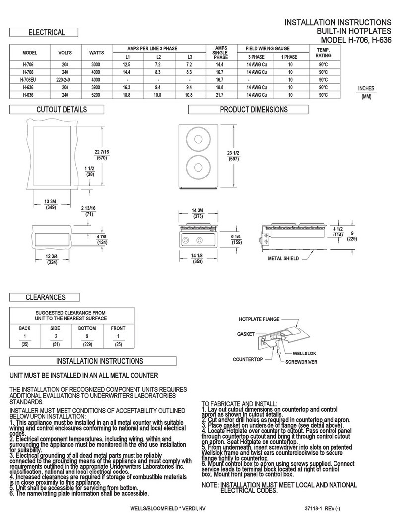
UNIT MUST BE INSTALLED IN AN ALL METAL COUNTER
INSTALLATION INSTRUCTIONS
THE INSTALLATION OF RECOGNIZED COMPONENT UNITS REQUIRES
ADDITIONAL EVALUATIONS TO UNDERWRITERS LABORATORIES
STANDARDS.
INSTALLER MUST MEET CONDITIONS OF ACCEPTABILITY OUTLINED
BELOW UPON INSTALLATION:
1. This appliance must be installed in an all metal counter with suitable
wiring and control enclosures conforming to national and local electrical
codes.
2. Electrical component temperatures, including wiring, within and
surrounding the appliance must be monitored in the end use installation
for suitability.
3. Electrical grounding of all dead metal parts must be reliably
connected to the grounding means of the appliance and must comply with
requirements outlined in the appropriate Underwriters Laboratories Inc.
classification, national and local electrical codes.
4. Increased clearances are required if storage of combustible materials
is in close proximity to this appliance.
5. Unit shall be accessible for servicing from bottom.
6. The name/rating plate information shall be accessible.
TO FABRICATE AND INSTALL:
1. Lay out cutout dimensions on countertop and control
apron as shown in cutout details.
2. Cut and/or drill holes as required in countertop and apron.
3. Removable Drip Tray located directly below heating element
must be installed by fabricator.
4. Lower control panel through countertop opening. Do not
disconnect the lead wires.
5. Snap trim ring and heating element into countertop cutout.
NOTE Orientation. The heating element should be positioned so
that the terminal insulating block is to the left and the front
retaining clip fits into the notch in the cutout.
6. Mount control box to apron using screws supplied. Connect
service leads to terminal block located at right of control box.
NOTE: INSTALLATION MUST MEET LOCAL AND NATIONAL
ELECTRICAL CODES.
MODEL VOLTS WATTS AMPS PHASE WIRING TEMP.
FIELD
GAUGE RATING
H-336
H-336 240
208 2000
2400
9.4
10.8 SINGLE
SINGLE 14 AWB Cu
14 AWB Cu
90°C
UNIT TO THE NEAREST SURFACE*
MINIMUM CLEARANCE REQUIRED
4 1/8
(105)
8
(203)(51)
21
(25)
FRONTBOTTOMSIDEBACK
CLEARANCES
PRODUCT DIMENSIONSCUTOUT DETAILS
ELECTRICAL
WELLS/BLOOMFIELD * VERDI, NV
MODEL H-336
INSTALLATION INSTRUCTIONS
37117-1 REV (-)
BUILT-IN HOTPLATE
SEE DETAIL 'A'
DETAIL 'A'
METAL SHIELD
90°C INCHES
(MM)