Blue Demon TRUE VIEW PANO V2 User manual
Digital Product
TRUE COLOR
180° SIDE VIEW
AUTO DARKENING WELDING HELMET
PANO V2
TRUE VIEW

2
TRUE VIEW PANO V2
3
4
5
7
8
15
16
18
20
*TRUE COLOR vision on the work piece both prior and during welding, which means
improved quality and higher efficiency.
*Overall-process protection against ultraviolet (UV) and infrared (IR ) radiation. TRUE
VIEW PANO V2 is equipped with lithium battery and solar cells that extends the life of the
battery.
*The product is in full conformity with related ANSI, CE. CSA, AS/NZS safety standards.
INDEX
WARNING
CORRECT USE OF THE WELDING HELMET
OPERATING INSTRUCTIONS
ADJUSTMENT INSTRUCTIONS
TECHNICAL SPECIFICATIONS
ILLUSTRATION
DISASSEMBLY AND ASSEMBLY INSTRUCTIONS
TROUBLESHOOTING
21
RELATED PARTS LIST AND WARRANTY
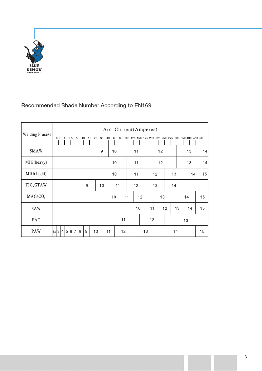
SHADE NUMBER
PAGE
TRUE VIEW PANO V2
Adjust shade pursuant to the field condition.
SHADE NUMBER

4
WARNING
READ CAREFULLY AND UNDERSTAND THESE
INSTRUCTIONS BEFORE USING THE HELMET
If the auto-darkening filter is cracked, stop using the helmet: UV/IR protection may
be compromised, resulting in burns to the eyes and skin.
During the welding process, heat and radiation are released.
• FUMES AND GASES can be dangerous to your health.
• Keep your head out of fumes.
• Use enough ventilation, exhaust at the arc, or both, to keep fumes and gases
away from your breathing zone and general area.
• ARC RAYS can injure eyes and burn skin.
• Before welding, always inspect helmet and filter lens to be sure they are fitted
properly, in good condition and not damaged.
• Check to see that the clear lens is clean and securely attached to the helmet.
• Always wear safety glasses or goggles under the welding helmet and protective
clothing, to protect your skin from radiation, burns and spatter.
• Ensure that optical radiation from other welder’s arcs in the immediate area
does not enter in from behind the helmet and auto-darkening filter.
Welding produces sparks and drops of molten metal that fly in all directions.
• The protective helmet must be worn to avoid potentially serious physical damages.
• Appropriate additional safety clothing must be worn to protect the rest of the body.
TRUE VIEW PANO V2
TRUE VIEW PANO V2 welding helmets are designed to protect the eyes and face
from sparks, spatter and harmful radiation under normal welding conditions. The
welding helmets may only be used for welding and not for other purposes. They
are suitable for use with virtually all welding process, except oxy-acetylene, laser
and gas welding procedures. They will not protect against severe impact hazards,
including fragments from grinding disks, explosive devices or corrosive liquids.
Machine guards and appropriate protection must be used. Avoid work positions
that could expose unprotected areas of the body to sparks spatter, direct and/or
reflected radiation. Use adequate protection if exposure can not be avoided.

5
CORRECT USE OF THE WELDING HELMET
• Before using the helmet, make sure that:
• the front cover lens, and the filter are in the correct position and correctly fixed
in place;
• all the sensors and the cells are not obstructed;
• the protection films on both screens are removed;
• the red light is off, otherwise change the batteries.
•Keep the filter viewing area as close as possible to the eyes during welding.
•When welding for extended periods, occasionally check the helmet and make
sure there are no signs of deformation or deterioration.
•Do not use the helmet without the transparent filter protections (internal and
external): non-observance may cause a safety hazard or irreparable damage to
the filter.
•Subjects with particularly sensitive skin must take extra care: materials that may
come into contact with the skin can cause allergic reactions.
•
MAINTENANCE
•Regularly check the condition of the helmet and change any damaged parts.
•Replace the external/internal transparent filter protection if it is damaged.
•Do not immerse the filter in water or other liquids; do not use solvents to clean the
filter.
•Do not put any heavy tools/objects in or on the helmet in order not to damage the
filter or the protective screens.
• Keep the helmet away from flames.
•Do not drop the helmet.
•Do not place the helmet too close to the welding area.
•Remove batteries when the helmet is not in use for long periods of time.
•Respect the temperature:
• use: -5°C (+23°F) ÷ +55°C (+131°F)
• storage: -20°C (-4°F) ÷ +70°C (+158°F).
TRUE VIEW PANO V2
Check that the protection level matches your welding process. If the helmet
presents operation problems, refer to the “troubleshooting” chapter; if the
problem persists, immediately stop using the helmet and contact the person in
charge or a distributor.

6
•Place the helmet in a way that does not allow its dimension to deform, or the viewing
filter to break.
•Do not allow the filter to come into contact with liquid and dirt.
•Do not open the filter container. Do not use any tools or other sharp objects to remove
any components of filter or helmet.
•
Do not use replacement parts other than those original ones: unauthorized modifications
and replacement parts will void the warranty and expose the operator to the risk of
personal injury.
CLEANING
Keep the filter, the sensor and the solar cell clean.
After using the helmet and before putting it away, it must be checked to verify integrity
and to eliminate any drops of molten metal.
The cartridge and the front cover lens must be cleaned at regular intervals with clean
cotton, a soft cloth or a special rag for lens. Do not use strong cleaning agents or
solvents: clean the inside and the outside of the helmet with a neutral disinfectant
product.
Non-observance of this regulation can expose the operator to health risks
and void warranty.
We will not accept any liability if the welding helmet is used for other
purposes or if these instructions are disregarded.
TRUE VIEW PANO V2

OPERATING INSTRUCTIONS
Check the front cover lens to make sure that they are clean, and that no dirt is covering
the sensors on the front of filter cartridge. Also check the front / rear cover lens and the
front lens retaining snap joint to make sure that they are secure.
7
TRUE VIEW PANO V2
Inspect all operating parts before each use for signs of wear or damage. Any
scratched, cracked, or pitted parts should be replaced immediately before using again
to avoid severe personal injury.
Adjust headband so that the helmet is seated as low as possible on the head and
close to your face. Adjust helmet's angle when in the lowered position by pressing the
side adjustable button.
Do not make any modifications to either the welding lens or helmet, other than those
specified in this manual.
Failure to follow these warnings and/or failure to follow all of the operating instructions
could result in severe personal injury.

8
ADJUSTMENT INSTRUCTIONS
Basic Functional Parameters
GRIND
WELD
SHADE
Parameter
SENS DELAY
3 0 No Display
No Display
10 1~4
Mode
Note:
Note:
Table 2 PANO V2 Side window function parameters of two operation modes
PANO V2 has one main window and two side windows.
The main window and two side windows have independent working modes to
choose from.
The main window has three operating modes: GRIND, WELD and CUT. The
specific function of the three operation modes parameters are shown in table 1.
The side window has two operating modes: GRIND and WELD. The specific function
of the two operation modes parameters are shown in table 2.
1、0 to 9 of the delay time corresponds to 0.06s to 1.0s, 0 is suitable for TAC
welding;
2、In the function of Welding and Cutting modes, sensitivity and delay time
can be set differently.
1、The two side windows have separate modes and parameter settings.
2、In welding mode when sensitivity set to 1, the side window will be
darkening follow the main window. When sensitivity set to 2, the side window
darkening follows the main window with low sensitivity. When sensitivity set to
GRIND
WELD
CUT
SHADE
Parameter
SENS DELAY
3 0 No Display
8~13 1~8
1~8
0~9
0~94~8
Mode
Table 1 PANO V2 Main window function parameters of three operation modes
TRUE VIEW PANO V2

9
Table 3 PANO V2 Main window Optional features of three operation modes
Main window Advanced Function
3, the side window darkening follows the main window with high sensitivity.
When sensitivity set to 4, the side window will stay dark.
PANO V2 in order to improve the convenience and comfort of users, add 4 optional
features and one-button grinding outside: Automatic Shade Number Adjust,
Automatic Sensitivity Adjust, Automatic Delay Time Adjust and Gradual Return. The
optional features of three operation modes of the main window are shown in table 3.
The outside grinding button is a self-recovery button, which can quickly switch the
working mode of the main window to grinding and press it again to return back the
previous working mode. When grinding button switches the working mode of the
main window to grinding, the main window will flash twice, and when the working
modes switches to the previous working mode, the main window will flash once.
GRIND
WELD
CUT
No
No
Yes
No
No
Yes
No
No
Yes
No
Yes
Yes
Automatic Shade
Number Adjust Sensitivity Adjust Delay Time Adjust Return
Automatic Automatic Gradual
Optional
Features
Mode
Function Definition Of The Display Area
Figure 1 is the display area, it has 10 function buttons, LCD display and LED lights,
which is explained next.
Figure 1 Display Area
TRUE VIEW PANO V2

10
(1)Main window Function Buttons
HIGH
HOLD: AUTO
1.Short Press -Increase the sensitivity.
2.Long Press - In the cut or weld mode,
set sensitivity automatically. (In the
process of automatic set sensitivity,
SENS area will be shown“AUTO”,
sensitivity numbers increase from 0
to 8 in turn)
1. Short Press-Press 0.1s to increase
the sensitivity. Release the button and
press again to increase the sensitivity
again.
2.Long Press-Press over 1.5s to set
sensitivity automatically for one time.
MIN
HOLD: AUTO
1.Short Press-Decrease the delay time.
2.Long Press-Enter or exit automatic
delay time function(When automatic
delay time function is enabled, the
screen of DELAY area will show“AUTO”)
1. Short Press-Press 0.1s to decrease
the delay time. Release the button and
press again to decrease the delay time
again.
2. Long Press-Press over 1.5s to enter
automatic delay time function and press
over 1.5s again to exit automatic delay
time function.
Function The usage the ButtonsButtons
MODE
A/M
HOLD: TEST
1.Short Press-Switching Mode:
GRIND—WELD—CUT—GRIND.
1.Short Press-Press 0.1s to switch the
mode. Release the button and press
again to switch mode again.
1.Short Press-In the welding mode
switch automatic or manual setting
the shade number.
2. Long Press-Test Function: Screen
Flashes—Grind—Cut—Weld.
1. Short Press-Short press to switch
automatic or manual setting the shade
number.
2.Long Press-Press over 1.5s to start
the TEST for one time.
LTR
DKR
LOW
1.Short Press-Decrease the shade
number.
2.Long Press-In the welding and
automatic shade number mode,
main window quickly decreases
the shade number.
1.Short Press-Short press to decrease
the shade number. Release the button
and press again to decrease the shade
number again.
2.Long Press-Press over 1.5s to decrease
the shade number quickly.
1.Short Press-Increase the shade
number.
2.2.Long Press-In the welding and
automatic shade number mode,
main window quickly increases the
shade number.
1.Short Press-Short press to increase
the shade number. Release the button
and press again to increase the shade
number again.
2.Long Press-Press over 1.5s to increase
the shade number quickly.
1.Short Press-Decrease the sensitivity.
2.Long Press- Anti-light interference
mode on/off. When Anti-light interference
is on, the sensitivity area displays a bulb
icon.
1.Short Press-Press 0.1s to decrease
the sensitivity. Release the button and
press again to decrease the sensitivity
again.
2.Long Press- Press over 1.5s to turn
on/off the Anti-light interference mode.
TRUE VIEW PANO V2

11
1.Short Press-Increase the delay time.
2.Long Press- In the weld mode, enter
or exit automatic shade number gradual
return.( When gradual return function
is enabled, the screen of DELAY
area will show “G” )
1、Short Press-Press 0.1s to increase
the delay time. Release the button and
press again to increase the delay time
again.
2、Long Press-Press over 1.5s to enter
automatic shade number gradual return
and press over 1.5s again to exit gradual
return.
MAX
HOLD: Gradual
(3)LCD Display
(2)Side window Function Buttons
Function The usage the ButtonsButtons
L
FILTER
R
FILTER
1、Short Press-Setting the left window
and press the button once to increase
the sensitivity. When enter the setting
of left window, the sensitivity area of
screen will display ”L” and left window
will flash. After setting the parameters,
if there is no keystroke, the LCD
screen will be automatically return to
the parameter interface of the main
window after 8 seconds.
2、Long Press-Quickly back to the
main window parameter display
screen.
1、Short Press-Press 0.1s to
increase the sensitivity. Release the
button and press again to increase
the sensitivity again.
2、Long Press- Press over 1.5s to
main window parameter display
screen.
1.Short Press- Setting the left window
and press the button once to increase
the sensitivity. When enter the setting
of right window, the sensitivity area of
screen will display” R” and right
window will flash. After setting the
parameters, if there is no keystroke,
the LCD screen will be automatically
return to the parameter interface of the
main window after 8 seconds.
2.Long Press-Quickly back to the main
window parameter display screen.
1.Short Press-Press 0.1s to increase
the sensitivity. Release the button
and press again to increase the
sensitivity again.
2.Long Press-Press over 1.5s to
main window parameter display
screen.
LCD Display have four parts: Mode, Shade, Sensitivity and Delay time.
1)GRIND, WELD, CUT indicates the current work mode.
TRUE VIEW PANO V2

12
(4)LCD Display
Sleep and wake up
2)Sensitivity: In the WELD or CUT mode, SENS area will be shown the number. 0 for
the grinding. For main window, 1 is the minimum sensitivity, and 8 for the maximum
sensitivity. For side window, 1 is the minimum sensitivity, and 4 for the maximum
sensitivity. The main window has Anti-light interference mode. When working in a strong
light environment turn the Anti-light interference mode on, the bulb icon will be displayed
in the SENS area on the screen. When automatic sensitivity function is enabled, SENS
area will be shown“AUTO”. The sensitivity numbers will increase from 1 to 8 in turn, and
stop at the gear number which is automatically set. Then the system will quit the
automatic sensitivity setting mode.
3)Delay time: DELAY area will be shown current number. When automatic delay time
function is enabled, DELAY area will be shown“AUTO”. The numbers on the screen can
adjust from -9 to +9 . In the weld mode, When gradual return function is enabled, the
screen of DELAY area will show“G”.
4)Low battery : When the battery is low, the screen will display low battery, indicating
that the batteries need to be charged.
There are two kinds of LED Light mode: Flash and always light. Different LED light
indicators are shown in table 4.
Table 4 Different LED light indicators
Note: The main window in the grind mode when the battery is not enough, the LED will
indicate lack of battery.
Operation Condition LED Indicator
Grind
Lack of battery (empty)
Red light for 2s and flash for 0.3s
Red light always on and the
display flashes a low-power icon
every 5s
In order to extend the service life of the battery, auto darkening welding filter under the
condition of environmental light intensity is less than 1lx and without arc for a long time,
need to enter a dormant state and work in low power mode. In a dormant mode, when
TRUE VIEW PANO V2
13
Basic function of the headlamp
the environmental light intensity is more than 1lx, auto darkening welding filter will be
working normally in 10s.
For different welding environments, the lens is integrated with a built-in headlamp.
Headlamps have two levels of brightness, high (100lm) and low (50lm).
1)Function
Headlamp has two working modes: manual and automatic. The headlamp manual mode
is continuously lit at a fixed brightness. In the automatic mode, the headlamp will be
automatically extinguished after the welding arc, and the headlamp will be lit immediately
after the welding arc is extinguished. The main advantage of automatic mode is to extend
the use time of the headlamp.
① Short press to switch the brightness in the manual mode:
Highlight → low light → Off → high light
②Long press to enter the automatic mode, the light will blink twice quickly. Short press at
any time to return to the manual mode. The brightness of the automatic mode is
determined by the brightness of the current manual mode, as shown in the following
table:
2)Charging
When the Low BAT indicator is steady red and the display displays the low charge, the
battery needs to be charged. You can use the standard TYPE-C charging interface to
plug into the TYPE-C interface on the upper part of the lens. When the lens is charging,
the charging indicator will light up. The red light indicates that the lens is charging and the
green light indicates that the charging is completed.
3)Low battery protection
When the battery is low, the headlamp will be forced to automatically turn off to save
power, so as to ensure that the auto darkening welding lens can still work normally for
more than 7 days.
In Manual Mode Highlight Low light Off
Brightness after long press
to enter the automatic mode Highlight Low light Highlight
TRUE VIEW PANO V2

14
The helmet should be adjusted to cover the eyes and face effectively while welding.
The position of the forehead band and rear headband can be manually adjusted to
fit securely. Rotate the gear to adjust the tightness until it feels comfortable.The front
and rear headbands should be adjusted to tightly cover the forehead and the backside
of head. See figure 2a.
Headgear adjustment:
Headgear depth:
The depth of the headgear can be adjusted to the position that the headgear sits above
your brow.Tighten/loosen the two slotted straps to fit the top of your head. See figure 2b.
The distance from the lens can be adjusted by pressing side pins and move sliders
simultaneously. There are 5 distance positions available for adjustment. See figure 2c.
Distance between lens and face:
The ideal helmet position is where your eyes are at 90°angle behind the lens.There
are 7 angle limitation positions available for adjustment. Press side buttons and move
the sliders simultaneously to make the helmet obtain the required angle limitation
position.See figure 2d.
Angle limitation position:
FIGURE 2
ab
cd
As a result of above mechanism action, the welder surely feels more
comfortable than before and are in working with more high proficiency
at any time.
Headgear
TRUE VIEW PANO V2

15
TECHNICAL SPECIFICATIONS
Main Window:
Light state: DIN3
Dark state: DIN 4-8/8-13
Main window viewing area: 114.5x85.5 mm (4.50” x 3.36”)
Side Window:
Light state: DIN3
Dark state: DIN 10
Side window viewing area: 2(pcs)x36.2(Top)/81.8(Bottom)x68.6(Height) mm
(2(pcs)x1.42(Top)” /3.22(Bottom) x2.70(Height)”)
Sensors: 7
Optical class: 1/1/1/1
True color: YES
Tig capability: >2A
Control: Digital
Shade control: Auto / Manual
Shade deviation of auto shade: -2.0 - +2.0
Sensitivity: 1-8, Automatic
Delay: 0.06 - 1.0S
Manual: YES
Auto mode: YES ( -/+9 steps adjustment )
Gradual: YES
TAC welding: YES
Gradual shade return to clear state: YES
Switch time: 1/10000S
Mode: CUT/WELD/GRIND
Power supply:
Auto ON / OFF: YES
Power backup: Solar panel & battery 2*CR2032
Test: YES
UV & IR protection: Up to shade 16
TRUE VIEW PANO V2
16
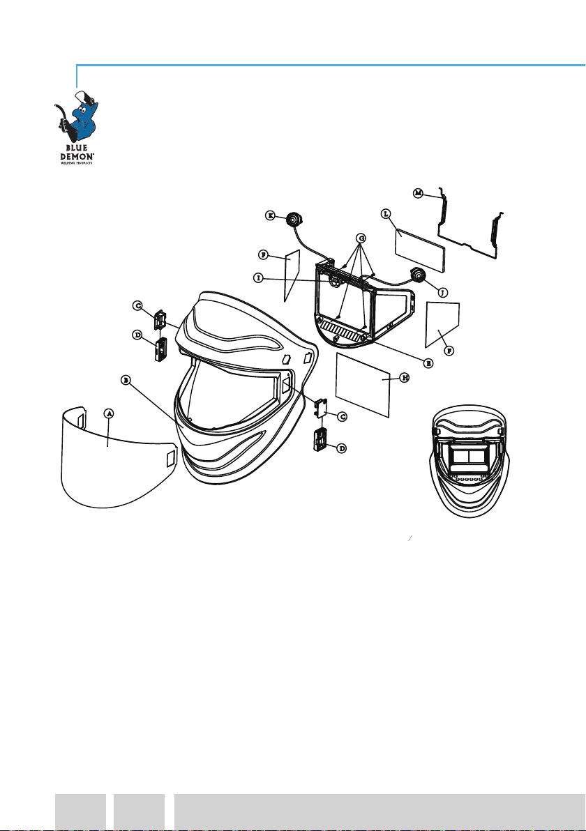
Main Part
ILLUSTRATION
E
A
G
B
Front protection plate
Snap joint for protection plate
Lock for snap joint of protection plate
Helmet shell
C
D
Rear protection plate 01
Auto darkening lens
F
Screw
L
H
I
Rear protection plate 02
Grinding button
Light switch button
light
J
K
Magnifying giass
Magnifying giass
M
Side Window Light Barrier
TRUE VIEW PANO V2
17
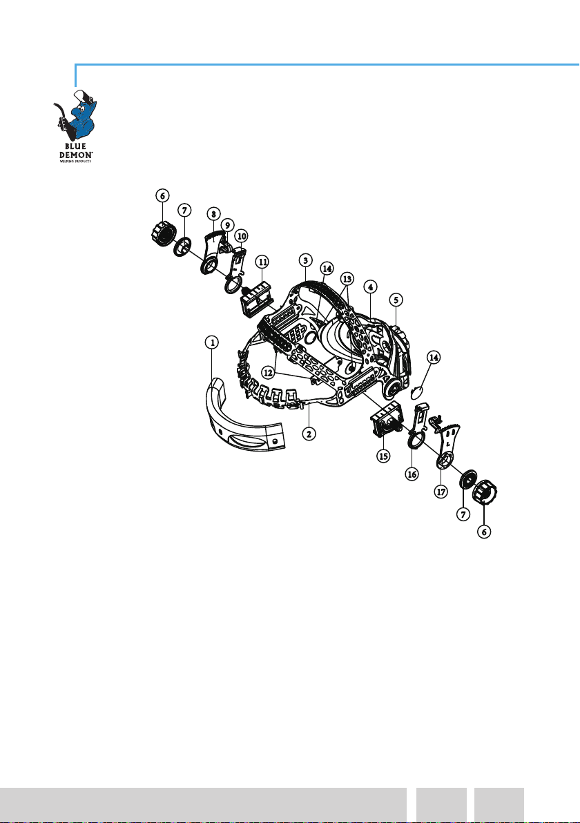
Headgear
5.Occipital pad
7.Washer
8.Right limitation washer
9.Angle pin
10.Right adjustable washer
11.Right slider
12.Side trim
13.Rotating shaft inside trim
14.Rotating shaft outside trim
6.Headband adjusting nut 15.Left slider
16.Left adjustable washer
17.Left limitation washer
1.Sweatband
4.Left belt
3.Right belt
2.Forehead band
TRUE VIEW PANO V2

18
DISASSEMBLY AND ASSEMBLY
INSTRUCTIONS
Protection Plate
1. Unlock the snap joint of protection plate if it is locked (A).
Press the snap joint for protection plate and then take out
the plate (A).
2. Change another protection plate and insert the snap joint
(make sure “a” side close to the helmet) and then lock it
(B).
3. Insert a finger into the semicircular hole and pull out the
inner protection lens (C). Remove protection film from
lens.
Place inside protection lens (C) back into the front of the
helmet by inserting one side of the lens into either side
slot and then bend the lens just enough that it will slip
into the other side slot.
Lock
Insertion
1
A
2
B
Unlock
Press
C
3
a
b
TRUE VIEW PANO V2

I
7
19
DISASSEMBLY AND ASSEMBLY
INSTRUCTIONS
Battery
7. Paste the control panel (I).
5. Peel off the control panel (E).
6. Loose the screw (F) and take out the filter (G) assembly from
the shell.
Tighten the screws (H).
6
4. Using the battery remover to take out the battery (D).
Change the battery and then put them back.
E
F
5
H
G
Filter
D
4
TRUE VIEW PANO V2

The filter does not darken or is
unstable when switching from
light to dark and viceversa
The external transparent protection of the filter is
dirty or damaged
Change the external transparent
protection
The sensors are dirty Clean the sensor surface
The level of the welding current level (sensitivity)
is too low
Increase sensitivity
The batteries are not in good condition or not
properly inserted
Replace the batteries or remove them
and re-insert them properly
Battery terminals and the contact surfaces of the
filter are dirty or oxidized
Clean both
The switch “WELD-GRIND” on the filter is in
position “GRIND”
Place the switch in the “WELD”
Slow switching The operating temperature is too low Do not use at temperatures
under -5°C (+23°F).
The external or/and internal protection of the filter
is/are dirty or damaged
Clean the dirty components and
replace the damaged ones
Not enough light in the surrounding area
The scale number is not set correctly, or the fixed
scale number is not suitable
Where possible, select the correct
number
Filter darkening without arc
being struck
Sensitivity is too high Adjust sensitivity to the right level
Filter remains dark after
completing a weld
Delay set too high
Ambient light is too bright
Adjust delay.
Reduce light level
Weld spatter is damaging
the filter
Missed, damaged, broken, distorted front cover Replace front cover lens
Some common problems listed below, together with their possible solutions, can
arise when using the helmet:
TROUBLESHOOTING
PROBLEM POSSIBLE CAUSE SOLUTION
ATTENTION! If the described malfunctions cannot be solved, stop using the
helmet immediately and contact Blue Demon Welding Products
Poor visibility
20
TRUE VIEW PANO V2
Table of contents
Other Blue Demon Welding Accessories manuals


