Blue I HYDROGUARD HG-702 User manual

HYDROGUARD®HG-702
Water Quality Analyzer
User Manual
March 2015
Document ID HG702UM1.36

2218 Ha'melacha St., Rosh Ha'ayin 4809148, Israel * Tel: 972-9-7680004 * Fax 972-9-7652331
www.blueitechnologies.com
ii
No part of this publication may be reproduced, transmitted,
transcribed, stored in a retrieval system, or translated into
any language or any computer language, in any form or by
any third party, without the prior written permission of Blue
I Water Technologies Ltd.
Disclaimer
Blue I Water Technologies Ltd. does not accept any
responsibility for any damage caused to its products by
unauthorized personnel. Use of non-Blue I Water
Technologies’ reagents and/or replacement parts will void
all warranties.
Trademark Acknowledgements
HG-702 is a registered trademark of Blue I Water
Technologies Ltd.
Copyright © 2014 by Blue I Water Technologies Ltd.

2218 Ha'melacha St., Rosh Ha'ayin 4809148, Israel * Tel: 972-9-7680004 * Fax 972-9-7652331
www.blueitechnologies.com
iii
Table of Contents
1. General Safety Precautions ............................................................................................... 7
2. Preface............................................................................................................................... 9
2.1 Intended Use ............................................................................................................. 9
2.2 Safety Precautions..................................................................................................... 9
3. Overview............................................................................................................................. 9
3.1 The HYDROGUARD Solution ................................................................................... 9
3.2 Measurements and Features................................................................................... 10
3.2.1 Wireless Management Package* ........................................................................ 10
3.3 System Components ............................................................................................... 10
4. Installation ........................................................................................................................ 13
4.1 Working Environment .............................................................................................. 13
4.2 Selecting a Location ................................................................................................ 13
4.3 Site Requirements and Installation.......................................................................... 13
4.3.1 Mechanical Installation ........................................................................................ 14
4.4 Plumbing Requirements and Installation................................................................. 14
4.4.1 Water Supply and Drainage................................................................................. 14
4.4.2 Water Supply....................................................................................................... 14
4.4.3 Drainage .............................................................................................................. 14
4.5 Electrical Requirements and Installation ................................................................. 15
4.5.1 Connecting the Main Electrical Power................................................................. 15
4.5.2 Chlorine Shock Mode .......................................................................................... 17
4.5.3 Input Switches ..................................................................................................... 17
5. First Time Operation and Calibration ............................................................................... 18
5.1 Installing Additional Sensors and Meters ................................................................ 18
5.2 Installing Reagents .................................................................................................. 18
5.3 First Time Menu Setup ............................................................................................ 20
5.3.1 HYDROGUARD Control Panel............................................................................ 21
5.3.2 Operator Menu..................................................................................................... 21
5.3.3 Configuration Settings in the Operator Menu...................................................... 24
5.3.4 Technician Menu ................................................................................................. 24
5.3.5 Configuring Settings in the Technician Menu...................................................... 26
5.4 Calibration................................................................................................................ 27
5.4.1 Chlorine Calibration ............................................................................................. 27
5.4.2 Calibrating other Sensors and Meters................................................................. 28
5.5 Calibration and Initial Operation Checklist .............................................................. 28
6. Routine Operation and Maintenance ............................................................................... 28
6.1 Monitoring HYDROGUARD Alarms......................................................................... 29

2218 Ha'melacha St., Rosh Ha'ayin 4809148, Israel * Tel: 972-9-7680004 * Fax 972-9-7652331
www.blueitechnologies.com
iv
6.2 Replacing Reagents ................................................................................................ 31
6.3 Cleaning the Filter.................................................................................................... 31
6.4 Shut-Down and Winterizing..................................................................................... 31
6.5 Start-up and Preventive Maintenance ..................................................................... 32
6.5.1 Replacing Reagent Pump Head and Tubes........................................................ 32
6.6 Troubleshooting....................................................................................................... 33
6.7 Replacing Components ........................................................................................... 36
6.7.1 Replacing Flow Switch......................................................................................... 36
6.7.2 Replacing Reagent Siphons................................................................................ 36
6.7.3 Replacing the reagent level sensor ..................................................................... 36
6.7.4 Replacing Reagent Pumps.................................................................................. 37
6.7.5 Replacing Colorimeter......................................................................................... 37
6.7.6 Replacing Colorimeter Solenoid Valve................................................................ 38
6.7.7 Replacing Control Panel Module (electronics card) ............................................ 38
6.7.8 Replacing I/O Module .......................................................................................... 38
6.7.9 Replacing Colorimetric Module............................................................................ 39
6.7.10 Module Software Update................................................................................. 39
7. Additional Measurements and Features .......................................................................... 39
7.1 Additional Measurements........................................................................................ 39
7.2 Free + Total Chlorine Measurements...................................................................... 40
7.2.1 Installation............................................................................................................ 40
7.2.2 Installing DPD3 Reagent ..................................................................................... 40
7.2.3 Additional Menus and First Time Set-up ............................................................. 40
7.2.4 Activate Total Chlorine Monitoring....................................................................... 40
7.2.5 Routine Maintenance........................................................................................... 41
7.2.5.1 Reagent Replacement..................................................................................... 41
7.2.5.2 Calibration........................................................................................................ 41
7.3 pH, ORP and Temperature Measurements............................................................. 41
7.3.1 Installation............................................................................................................ 41
7.3.2 Routine Maintenance........................................................................................... 42
7.3.2.1 Calibration........................................................................................................ 42
7.3.2.2 Replacing Sensors........................................................................................... 43
7.3.3 Shut-down and Winterizing.................................................................................. 44
7.4 Turbidity Measurements.......................................................................................... 45
7.4.1 Installation............................................................................................................ 45
7.4.2 Relay Wiring and Use.......................................................................................... 46
7.4.3 First Time Set-up and General Operation ........................................................... 47
7.4.4 Routine Maintenance........................................................................................... 48
7.4.4.1 Turbidity Calibration......................................................................................... 48
7.4.4.2 Cleaning the Turbidity Sensor ......................................................................... 48

2218 Ha'melacha St., Rosh Ha'ayin 4809148, Israel * Tel: 972-9-7680004 * Fax 972-9-7652331
www.blueitechnologies.com
v
7.4.4.3 Replacing Components ................................................................................... 48
7.4.5 Shut-down and Winterizing.................................................................................. 49
7.5 Conductivity Measurements.................................................................................... 49
7.5.1 Installation............................................................................................................ 49
7.5.2 First Time Set-up and General Operation ........................................................... 50
7.5.3 Routine Maintenance........................................................................................... 50
7.5.3.1 Conductivity Calibration................................................................................... 50
7.5.3.2 Cleaning the Conductivity Meter...................................................................... 50
7.5.3.3 Replacing the Conductivity Meter.................................................................... 50
7.5.4 Shut-down and Winterizing.................................................................................. 51
7.6 Flow Meter............................................................................................................... 51
7.6.1 Installation............................................................................................................ 51
7.6.2 Routine Maintenance and Troubleshooting......................................................... 52
7.7 Modbus Communication Protocol............................................................................ 52
7.8 Communication Options .......................................................................................... 57
7.8.1 Internal 4 to 20mA Output.................................................................................... 57
7.8.1.1 Installation........................................................................................................ 57
7.9 Chlorine Shock Mode .............................................................................................. 58
Appendix A: Relays and Closed-Loop Control........................................................................ 60
Connecting external equipment to the relays ...................................................................... 60
Wiring to Dosing Systems................................................................................................ 60
Proportional Control Overview............................................................................................. 61
Proportional Factor........................................................................................................... 61
Step By Step Proportional Settings.................................................................................. 63
Setting Pump Period ........................................................................................................ 63
Appendix B: Technical Specifications ..................................................................................... 64

2218 Ha'melacha St., Rosh Ha'ayin 4809148, Israel * Tel: 972-9-7680004 * Fax 972-9-7652331
www.blueitechnologies.com
vi
Table of Figures
Figure 1: HydroGuard 702 Main Components ........................................................................ 12
Figure 2: HydroGuard 702 Mounting Panel............................................................................. 14
Figure 3: Flow Cell and Colorimeter Inlet and Outlet .............................................................. 15
Figure 4: Jumper...................................................................................................................... 15
Figure 5: 115-120VAC setting ................................................................................................. 16
Figure 6: 200-230VAC setting ................................................................................................. 16
Figure 7: Flow cell and Colorimeter Inlet and outlet................................................................ 18
Figure 8: Reagent handling ..................................................................................................... 19
Figure 9: HydroGuard Control Panel....................................................................................... 21
Figure 10: Replacing all types of electronic modules (cards).................................................. 38
Figure 11: Installing new chipset............................................................................................. 39
Figure 12: Turbidity Sensor and Flow Cell .............................................................................. 46
Figure 13: Connecting Turbidity Sensor to Turbidity Module.................................................. 46
Figure 14: Relay positions on board........................................................................................ 60
Figure 15: Proportional Control of Chemical Dosing............................................................... 61
Figure 16: P-factor computation example ............................................................................... 62
Table of Tables
Table 1: Control panel structure.............................................................................................. 21
Table 2: Operator Menu Functions and Descriptions.............................................................. 22
Table 3: Operator’s Menu & variables limits ........................................................................... 23
Table 4: Technician Menu Functions and Descriptions........................................................... 25
Table 5: Technician Menu and Variable Limits ....................................................................... 26
Table 6: Calibration Table ....................................................................................................... 28
Table 7: Maintenance Table.................................................................................................... 29
Table 8: Alarm Description and Result.................................................................................... 30
Table 9: Troubleshooting Table............................................................................................... 33
Table 10: Additional Menus in the Operator Menu.................................................................. 40
Table 11: Additional Menus in the Technician Menu.............................................................. 40
Table 12: Modbus Configuration Options ............................................................................... 54
Table 13: Modbus Communications Options .......................................................................... 55
Table 14: Relays and their controlled dosing systems............................................................ 61

2218 Ha'melacha St., Rosh Ha'ayin 4809148, Israel * Tel: 972-9-7680004 * Fax 972-9-7652331
www.blueitechnologies.com
7
1. General Safety Precautions
This section presents important information intended to ensure safe and
effective use of this product.
Read the following carefully before handling the product. These warnings and
cautions must be followed carefully to avoid injury to yourself or damage to
equipment.
Warning: Only properly trained and licensed
electricians should attempt to wire or service the
electronic components of the analyzer/controller.
There is an Electrical Shock Hazard when
servicing this system.
Always verify that all electrical power source(s)
are off before opening the analyzer/controller
unit or attempting to service electronic
components or wiring.
Attention! Seuls des électriciens qualifiés ayant
reçu la formation adéquate peuvent
entreprendre le branchement, l’entretien ou la
réparation des composants électroniques de
l’analyseur/du contrôleur.
Il existe un risque de choc électrique lors de
l’entretien de ce système.
Ayez soin de toujours vérifier que la ou les
source(s) d’alimentation électrique est ou sont
bien déconnectée(s) avant d’ouvrir l’unité ou
d’entreprendre toute opération de service
technique et tout branchement des composants
électroniques.
Caution: Extreme caution should be used when
installing, operating, and maintaining the
HYDROGUARD®Analyzer. Only properly
trained technicians are authorized to install and
maintain the analyzer/controller.
Attention! Il y a lieu d’agir avec une extrême
prudence lors de l’installation, de la mise en
œuvre et de la maintenance du contrôleur
HYDROGUARD®. Seuls des techniciens dûment
formés à cet effet sont autorisés à effectuer
l’installation et la maintenance de l’analyseur/du
contrôleur.
Only properly trained and licensed operators
should attempt to make any changes to
chemical dosing levels.
Seuls des opérateurs qualifiés ayant reçu la
formation adéquate sont habilités à modifier les
dosages des produits chimiques utilisés.
Always follow local health and safety regulations
when performing any service on the
analyzer/controller unit or when changing
chemical dosing settings.
Conformez-vous sans exception aux consignes
locales de santé et de sécurité lorsque vous
effectuez toute opération technique sur
l’analyseur/le contrôleur, ou lorsque vous
modifiez les paramètres de dosages chimiques.
The main power supply may be connected to
either 110-120 or 220-240VAC 50/60Hz.
Switching between voltages is accomplished by
changing two (2) jumpers located above the
main power connection, to the left of the
transformer. For 110-120VAC, a 1amp fuse
should be use; for 220-240VAC, a 0.5amp fuse
should be used. These changes must be
completed prior to wiring.
L’alimentation générale peut être branchée sur
110-120 ou sur 220-240VAC 50/60Hz. Pour
basculer d’une tension à l’autre, il suffit de
changer les deux (2) cavaliers situés au-dessus
de la principale connexion électrique, à gauche
du transformateur. Une tension à 110-120VAC
requiert un fusible de 1 Amp. ; une tension à
220-240VAC requiert un fusible de 0,5 Amp.
Ces modifications doivent être accomplies avant
le branchement électrique.

2218 Ha'melacha St., Rosh Ha'ayin 4809148, Israel * Tel: 972-9-7680004 * Fax 972-9-7652331
www.blueitechnologies.com
8
Caution: Before connecting to a power source,
confirm that both jumpers are located on the
correct voltage and that the appropriate fuse is
in place.
Attention! Avant de relier l’appareil à une
quelconque alimentation électrique, vérifiez que
les deux cavaliers sont situés sur les valeurs
correctes de tension et que c’est le bon fusible
qui est en place.
Each relay connection is limited to 4 amps, to
prevent overheating. The relays may show a
higher rating but do not connect equipment
exceeding 4 amps.
Chaque connexion relais est limitée à 4 Amp.
afin d’éviter toute surchauffe. Même si les relais
affichent éventuellement une valeur supérieure,
ils ne se connecteront pas à un élément
dépassant 4 Amp.
All electrical connections should comply with
National Electrical Code (NEC) and all local
regulations.
Tous les branchements électriques doivent être
conformes au Code Electrique National (NEC –
National Electrical Code) ainsi qu’à toutes les
consignes locales.
Mixing reagents:
Caution: Use protective gear as recommended
in MSDS.
Mélanges réactifs:
Attention! Utilisez l’équipement de protection
préconisé dans la fiche de données de sécurité
(MSDS).
Caution: Do not use chemicals that reduce the
surface tension. When using hydrochloric acid,
observe all safety regulations.
Attention! N’utilisez pas de produits chimiques
susceptibles de réduire la tension superficielle.
Lors de l’utilisation d’acide chlorhydrique,
appliquez scrupuleusement toutes les consignes
pertinentes.
Caution: HYDROGUARD's control board unit
should not be opened except for initial
installation and troubleshooting, and should only
be opened by a trained and approved
technician.
Attention! Le tableau de commandes de
l’HYDROGUARD ne doit en aucun cas être
ouvert si ce n’est lors de l’installation initiale et
en cas de dépannage –auquel cas son
ouverture ne doit être effectuée que par un
technicien ayant reçu la formation adéquate et
dûment habilité.

2218 Ha'melacha St., Rosh Ha'ayin 4809148, Israel * Tel: 972-9-7680004 * Fax 972-9-7652331
www.blueitechnologies.com
9
2. Preface
2.1 Intended Use
This manual is for qualified and trained service technicians who will install and service the
HYDROGUARD HG-702 Water Quality Analyzer. It provides instructions on how to install the
HYDROGUARD system, how to integrate it with external chemical dosing systems and how
to calibrate, operate and maintain the system.
2.2 Safety Precautions
Warning
Only properly trained and licensed electricians should attempt to wire or service the electronic
components of the analyzer.
There is an Electrical Shock Hazard when servicing this system.
Always verify that all electrical power source(s) are off before opening the analyzer unit or
attempting to service electronic components or wiring.
Caution
Extreme caution should be used when installing, operating and maintaining the
HYDROGUARD HG-702 Water Quality Analyzer and Controller.
Only properly trained technicians are authorized to install and maintain the analyzer.
Only properly trained and licensed electricians should attempt any change to the system’s
electrical components.
Only properly trained and licensed operators should attempt to make any changes to
chemical dosing levels.
Always follow local health and safety regulations when performing any service on the
HYDROGUARD unit or changing chemical dosing settings.
3. Overview
The HYDROGUARD HG-702 Water Quality Analyzer continuously monitors chemical levels
in a process water application. HYDROGUARD automates free chlorine, total chlorine, pH,
ORP (Redox), temperature, turbidity, conductivity and/or flow rate, administering chemicals as
required, according to the results of these tests (closed loop).
3.1 The HYDROGUARD Solution
Various methods have been developed over the years to monitor the concentration and
balance of chemicals used in water treatment. The older manual methods of monitoring
chemical balance are neither objective nor effective. HYDROGUARD measures free or total
(and optionally both free and total) chlorine levels with a digital photometer, which has many
advantages over other types of sensors. Digital photometer testing is completely objective. It
is not dependent on lighting conditions or the operator’s eyesight, and is far more accurate. It
does not require frequent calibration and is compatible with all types of disinfectant systems.
HYDROGUARD performs colorimetric testing in a closed reading cell. It is the only system
that automatically and accurately measures free chlorine using small amounts of reagent.
Once installed and calibrated, HYDROGUARD is fully automatic. It will monitor and can
control dosing systems directly or indirectly, releasing the proper quantity of chemicals based
on frequent automatic measurements. HYDROGUARD is simple to use. Its straight-forward
control panel and parameters menu make chemical balance control an easy task. All basic
information can be viewed at a glance, and changing settings is as simple as scrolling through
the menu and adjusting the current settings.

2218 Ha'melacha St., Rosh Ha'ayin 4809148, Israel * Tel: 972-9-7680004 * Fax 972-9-7652331
www.blueitechnologies.com
10
3.2 Measurements and Features
The HYDROGUARD 702 comes standard with chlorine measurement and can be configured
to measure any combination of the following water quality parameters:
Free Chlorine
Total Chlorine
Both Free Chlorine and Total Chlorine
Optional Measurements:
Turbidity
Temperature or Conductivity
ORP (Redox) and Temperature
Flow Rate
Optional communication protocol
Modbus Protocol
Blue I Protocol
Communication options:
Internal 4 to 20 mA outputs (up to 6 channels)
Wireless modem
Ethernet
3.2.1 Wireless Management Package*
An advanced and unique HYDROGUARD option is the wireless modem which provides web-
based monitoring of up to 5 analyzers. This cellular communicator collects HYDROGUARD’s
alarms and readings and transmits them to a web-based application server. The information
is easily accessed via the Internet or mobile phone.
*The wireless modem is an optional module.
Note: Not all cellular companies support this wireless modem. Please contact Blue I Water
Technologies or your supplier for details. See the supplemental manual for instructions on
installing and using the modem.
3.3 System Components
HYDROGUARD has two primary units: the analyzing unit and the control unit. The analyzing
unit performs the actual measurements. It contains the following components:
Colorimetric Reading Cell –measures free or total (and optionally both free and total)
chlorine levels in the water using DPD reagents and a closed-cell, digital photometer.
Flow Cell –contains the sensors, including the pH, Redox (ORP) and temperature sensors.
Reagent Bottles –contains the reagents used by the colorimeter to measure chlorine levels
in the water.
Reagent Pumps and Solenoid Valve –accurately controls the flow of water and reagents
into the colorimeter, making every measurement as accurate as possible.
The control units include all electronics, the user interface and the software that controls the
measurements performed in the analyzing unit. It includes the following components:
I/O Module (Input/Output) –Power Supply to the analyzer and contains the dry-contact
relays for direct control of external dosing systems.

2218 Ha'melacha St., Rosh Ha'ayin 4809148, Israel * Tel: 972-9-7680004 * Fax 972-9-7652331
www.blueitechnologies.com
11
Control Panel Module –Calculates the measurement results and determines the required
chemical dosing to maintain an appropriate chemical balance in closed-loop systems. The
Control Panel Module also provides data to external communication devices such as the 4-
20mA outputs or the wireless communication package.
Keyboard Panel –mounted on the cover of the control module, it functions as
HYDROGUARD’s user interface. The control panel displays current measurements and
indicates alarms. All settings and adjustments are performed through the control panel.
Colorimeter Module –controls the colorimeter and associated components, such as the
reagent pumps and solenoid valve. It accurately calculates the chlorine level.
pH, Redox, Temp Module* –receives the signal from the pH, Redox, and temperature
probes.
Internal 4-20 Input Module* –contains connections for Turbidity, Conductivity meter and the
4-20 Flow Meter.
Internal 4-20 Output Module* –provides up to four 4-20mA outputs for any measured
variable.
*Optional Module

2218 Ha'melacha St., Rosh Ha'ayin 4809148, Israel * Tel: 972-9-7680004 * Fax 972-9-7652331
www.blueitechnologies.com
12
Figure 1: HYDROGUARD HG-702 Main Components

2218 Ha'melacha St., Rosh Ha'ayin 4809148, Israel * Tel: 972-9-7680004 * Fax 972-9-7652331
www.blueitechnologies.com
13
4. Installation
4.1 Working Environment
Pollution Degree: 2
Installation Category: 2
Altitude: 2,000 m
Humidity: 1 to 90% non-condensing
Electrical Supply: 100-115Vac, 1.0A or 200-230Vac, 0.5A, 50/60Hz
Temperature: 5°C to 45°C
4.2 Selecting a Location
Take extra time in selecting a location since the installation location will determine the ease of
the installation and future operation and maintenance. The location where HYDROGUARD is
installed is dependent on various considerations:
Convenient Access –The HYDROGUARD should be installed where it can easily be viewed
and operated.
Dry Area –The HYDROGUARD handles electricity and includes electronic circuitry that is
susceptible to short-circuiting and/or corrosion when exposed to water or high ambient
moisture levels.
Away from Chemicals –Many water treatment chemicals can be corrosive to
HYDROGUARD’s electronic circuitry. It is highly recommended that HYDROGUARD is not
installed adjacent to a storage area for chemicals or the dosing systems themselves.
Minimum Distance from Supply Pipe –The water sampling line that is connected to the
main pipe and that feeds the HYDROGUARD should be as short as possible. A long sample
creates an unnecessary delay between supply, measurement, analysis and chemical dosing.
Drainage –The location should easily allow the outlet of the colorimeter to gravity drain
without creating an obstacle (i.e. no pipe across walkway). The flow cell may be pressurized
to allow for return to the system under pressure.
Freezing Temperatures –The analyzer should be installed in a location that is not
susceptible to freezing temperatures. The reagents can freeze, preventing accurate readings
(even when thawed) and parts may be damaged due to expansion when ice forms.
4.3 Site Requirements and Installation
The HYDROGUARD assembly is wall mounted. It should be located on a wall where
operators and service technicians can easily access it for normal operation and maintenance.
It is also advisable to install it where the operators can easily view the readings and alarms.
The complete unit with all connections weighs 18 lbs. (8 kg), so it must be mounted securely
on a stable wall. The HYDROGUARD unit measures 26.3” x 13.1” (66.8 cm x 33.2 cm). The
base of the complete HYDROGUARD assembly should be mounted at least 24” (60 cm)
above the floor (preferably at eye level).
The HYDROGUARD unit and its mounting panel are not shipped with mounting screws or
anchors. The installer must provide screws and anchors that can hold the weight of the
HYDROGUARD unit, mounting panel, intake filter and electrical outlets and junction boxes.
The screws and anchors must be compatible with the wall where it will be installed.

2218 Ha'melacha St., Rosh Ha'ayin 4809148, Israel * Tel: 972-9-7680004 * Fax 972-9-7652331
www.blueitechnologies.com
14
4.3.1 Mechanical Installation
Illustrates steps 3 to 5 in the following procedure.
1. HYDROGUARD is shipped pre-mounted on a mounting panel, along with a water filter.
The mounting panel includes four screw holes, one in each corner.
2. Determine the location of one hole on the HYDROGUARD unit or on the mounting
panel.
3. Secure one corner of the HYDROGUARD unit or mounting panel to the wall.
4. Level the HYDROGUARD unit or mounting panel and mark the remaining three (3)
screw holes.
5. Secure the remaining corners to the wall using 5/16” (8 mm) screws.
4.4 Plumbing Requirements and Installation
4.4.1 Water Supply and Drainage
4.4.2 Water Supply
HYDROGUARD requires a pressurized water supply to the flow cell. An isolating valve must
be installed between the main line and the pipe (or tube) to the HYDROGUARD. The
minimum inlet pressure should be 4.4 psi (0.3 bar) and should not exceed 14.5 psi (1 bar)
using a pressure regulator attached to the outlet of the pre-filter. The distance from the main
pipe to the HYDROGUARD should be as short as possible, in order to minimize the delay
time between the water being sampled and HYDROGUARD measurement.
4.4.3 Drainage
A pressurized, vacuum, or gravity connection is required from the outlet of the flow cell to
return water from the flow cell to the water supply. A ¼” FNPT fitting is supplied for the flow
cell drain connection.
A gravity drainage connection is required for the water coming out from the colorimeter. The
length of the colorimeter drain line should be as short as possible and must have a constant
downward slope to prevent a backflow of water. A drain cap is located on the colorimeter
outlet to prevent the backup of water into the colorimeter if the drain line is blocked. A ½”
MNPT fitting is supplied for the colorimeter drain connection.
Figure 2: HydroGuard 702 Mounting Panel
2218 Ha'melacha St., Rosh Ha'ayin 4809148, Israel * Tel: 972-9-7680004 * Fax 972-9-7652331
www.blueitechnologies.com
15
Figure 4: Jumper
Note
The HYDROGUARD colorimeter drains water at zero (0) pressure. The drainage pipe should
be as straight as possible and have a constant downward slope and should not have any
bends where water flow can be restricted. If the colorimeter drains to a bucket or basin, the
end of the drainage pipe should terminate above the bucket or basin rim.
4.5 Electrical Requirements and Installation
HYDROGUARD requires a 115-120 or 200-230 VAC, 50/60 Hz electrical power source on a
separate 16A circuit in the plant room’s electrical board. The main HYDROGUARD power
supply should be connected to a non-dependent power supply, so that the unit remains
powered constantly. The active relays should be connected to a dependent power supply
(interlocked power supply).
4.5.1 Connecting the Main Electrical Power
Note
HG 702 default configuration is 115-120VAC unless 200-230VAC
configuration was ordered.
The Main Power Supply may be connected to either 115-120 or 200-
230VAC 50/60Hz. Switching between voltages is accomplished by
changing two (2) jumpers (Figure 4) located above the main power connection, to the left of
the transformer (Figure 5 & 6):
For 115-120VAC, a 1amp fuse should be used
For 200-230VAC, a 0.5amp fuse should be used
Note
These changes must be completed prior to wiring.
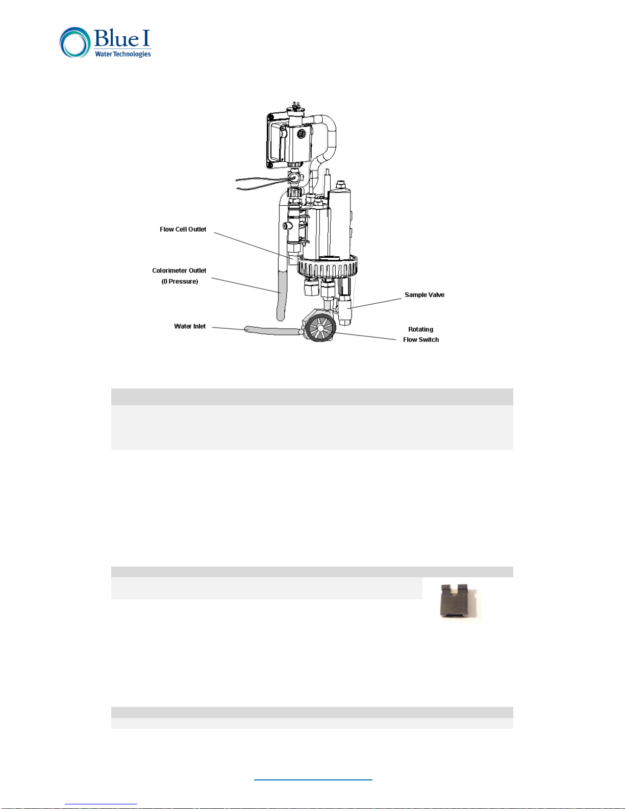
Figure 3: Flow Cell and Colorimeter Inlet and Outlet

2218 Ha'melacha St., Rosh Ha'ayin 4809148, Israel * Tel: 972-9-7680004 * Fax 972-9-7652331
www.blueitechnologies.com
16
To change the configuration use jumpers J21 & J22 on the I/O card. For 115-120VAC see the
jumpers setting per Figure 5. For 200-230VAC see jumpers setting per Figure 6.
Caution
Before making a connection to a power source, confirm that both jumpers are located on the
correct voltage and that the appropriate fuse is in place.
1. Verify that the power switch or circuit breaker to the non-dependent power source is
OFF.
2. Connect the line (live) wire to the I/O board connector marked Line.
Figure 5: 115-120VAC setting
Figure 6: 200-230VAC setting

2218 Ha'melacha St., Rosh Ha'ayin 4809148, Israel * Tel: 972-9-7680004 * Fax 972-9-7652331
www.blueitechnologies.com
17
3. Connect the neutral wire to the I/O board connector marked Neutral.
4. Connect the earth wire to the I/O Module connector marked Ground.
5. Continue with the other electrical connections.
6. Turn on electrical power only after all electrical connections have been completed.
For information on wiring and using the relays as dry contact or for control, see chlorine shock
mode.
4.5.2 Chlorine Shock Mode
Chlorine shock mode is available to provide a high level of chlorine for a relatively short
period of time.
Two menus control this feature:
1. Shock Chlorination
2. Cl Shock Set-point
a. Duration
During normal operation, the analyzer controller operates Cl dosing systems based on Cl Set
Point 1.
When Cl Shock mode is turned ON, the controller will automatically control the Cl dosing
system based on the Cl Shock Set Point. This will only affect Cl relay #1 and the 4-20mA
Control Output. Cl relay #2 will still be controlled based on Cl Set Point #2.
Once the Cl Shock Mode is turned ON, the controller controls the Cl Shock Set Point for the
user-selected Duration and then automatically shuts Cl Chlorination Mode OFF. Then the
controller returns to operating the Cl Set Point 1.
To turn on Cl Shock Mode:
1. Enter the Cl Shock Set-point, then press OK.
2. Enter the Duration, then press OK.
3. Turn Cl Shock Mode ON.
You will also need to adjust the Cl P-factor (technician menu). A low P-factor will make slower
changes to Cl dosing; a high P-factor will make faster changes to Cl dosing. If you have
trouble reaching the Cl set-point, use a higher P-factor. If you greatly overshoot the set-point,
use a lower P-factor.
4.5.3 Input Switches
Flow input switch terminal blocks on the I/O module allow for three input switches to be
connected to the system as additional layers of security against accidental chemical additions
when there is no flow. If a connection is expected but not detected at each input, the
analyzer/controller will indicate an alarm and will close all relays (and open the alarm relay).
Therefore, if a safety switch (flow, level, etc.) will not be installed, a fixed connection (jumper
wire) is required to allow the controller to operate.
Two flow switches and one flow meter may be connected:
Flow Switch (internal): Flow switch connected to the flow cell of analyzer. Supports
both 2 and 3 wire flow switches.
oIf a 2-wire switch is used, it should be connected to the “In” and “Gnd”
connections. If a 3-wire switch is used, the “VCC” connection will also be
used.
External Flow Switch: Connection for an external 2-wire flow switch. If an external
switch is not connected, a jumper must be installed for the analyzer to operate
properly.

2218 Ha'melacha St., Rosh Ha'ayin 4809148, Israel * Tel: 972-9-7680004 * Fax 972-9-7652331
www.blueitechnologies.com
18
Figure 7: Flow cell and Colorimeter Inlet and outlet
Flow Meter: Connection for 2 or 3-wire flow meter. The analyzer will not look for the
flow meter connection unless the option is turned ON in the technician menu;
therefore, no jumper is required if a meter is not installed.
Caution
Electrical connections depicted in this section are ONLY recommendations. All electrical
connections should comply with National Electrical code (NEC) and all local regulations.
5. First Time Operation and Calibration
5.1 Installing Additional Sensors and Meters
Install all additional sensors and meters and connect to the HG-702 main system, following
the supplemental manuals for each sensor or meter.
5.2 Installing Reagents
For Free Chlorine Only measurements, DPD1 reagent set will be used
For Total Chlorine Only measurements, DPD4 reagent set will be used.
For both Free and Total Cl measurements, DPD1 and DPD3 reagent sets will be used.
The reagents should be installed according to the labels located behind the reagent holder.
For systems ordered previously, please refer to the following installation:
For Free Cl Only: For Total Cl Only:
1. Free Chlorine Indicator (DPD #1) 1. Total Chlorine Indicator (DPD #4)
2. Free Chlorine Buffer (DPD #1) 2. Total Chlorine Buffer (DPD #4)
For Free Cl + Total Cl:
1. Free Chlorine Indicator (DPD #1)
2. Free Chlorine Buffer (DPD #1)
3. Total Chlorine Indicator (DPD #3)

2218 Ha'melacha St., Rosh Ha'ayin 4809148, Israel * Tel: 972-9-7680004 * Fax 972-9-7652331
www.blueitechnologies.com
19
Figure 8: Reagent handling
1) Open the HYDROGUARD Chlorine Indicator and Buffer kit. The following items should
be in the box:
600 ml bottle of chlorine buffer with a white label.
600 ml bottle of chlorine indicator fluid with a blue label.
Small bottle of chlorine indicator salt with a white label.
2) Remove the caps on both the indicator fluid and small indicator salt bottles.
3) Empty the entire contents of the indicator salt into the bottle of indicator fluid.
4) Place the cap on the bottle of chlorine indicator fluid and close tightly.
5) Turn the bottle upside-down slowly and carefully, so that no bubbles form in the fluid.
6) Repeat five (5) times until all the indicator salt is dissolved in the indicator fluid.
7) Place the reagent bottles in position:
a) Remove the cap from the reagent bottles.
b) Place the opening of the reagent bottle below the bottle siphons.
c) Lift the bottle up until the opening reaches the bottle siphon cap.
d) Push the lever above the siphon cover away from you, and push the reagent bottle
up.
e) Push the bottom of the bottle into position.
Caution
Do not refill the reagent bottles.
Do not mix or add reagent from other bottles.
Do not use any non-Blue I Water Technologies’reagents.
8) Prime the reagent pumps:
a) Press Menu on the control panel keypad until the Reagent Pump menu appears.
b) Press OK
c) Enter password (123 is default) using the up or down arrows

2218 Ha'melacha St., Rosh Ha'ayin 4809148, Israel * Tel: 972-9-7680004 * Fax 972-9-7652331
www.blueitechnologies.com
20
d) Press OK (OFF will appear on top line)
e) Press OK again (OFF will appear on the top and bottom lines)
f) Press UP to turn the reagent pumps ON
g) Press OK when the water flowing from the colorimeter has a red tint or reagent
drops are being formed at the needle tips.
h) Press Escape twice (2x) to return to the main screen
Note
If outside of the range of 0.2 to 10 ppm, remove the colorimeter cap and confirm that reagents
are being pumped.
5.3 First Time Menu Setup
This section describes how to configure the settings (set points, alarms, and calibrations)
through the HYDROGUARD control panel.
Caution
HYDROGUARD's control board unit should not be opened except for initial installation and
troubleshooting and should only be opened by a trained and approved technician.
Other manuals for HYDROGUARD HG-702
3
Table of contents
Other Blue I Measuring Instrument manuals


Popular Measuring Instrument manuals by other brands


FRER
FRER Q52A3H Series operating manual

Makita
Makita LD080P quick start

Teledyne
Teledyne Echotrac E20 Operator's manual

Agilent Technologies
Agilent Technologies Agilent 8163A user guide

Amptec Research
Amptec Research 620LK Installation, operation and maintenance manual

Larson Davis
Larson Davis SoundAdvisor 831C Reference manual


