Blue I HYDROGUARD HG-202 User manual
1 Water. Quality. Secured.
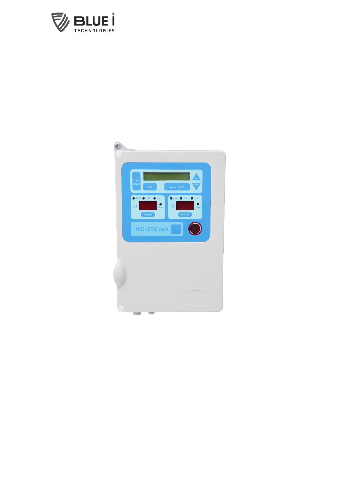
HYDROGUARD HG-202
Water Quality Analyzer
User manual
Version 4.1
2 Water. Quality. Secured.
Rev.
By
Changes made
Date
4.0
BM
Update to pictures, logo, chlorine electrode
31.7.19
1.4
BM
Installation Section Updated
11.8.19

3 Water. Quality. Secured.
Table of Contents
1 General Safety Precautions ...................................................................................4
2 Preface...................................................................................................................5
2.1 Intended Use ...................................................................................................5
2.2 Safety Precautions ..........................................................................................5
3 Overview.................................................................................................................6
3.1 Features and Modules.....................................................................................6
3.2 Remote Communications................................................................................6
3.3 System Components .......................................................................................6
4 Installation .............................................................................................................8
4.1 Selecting a Location ........................................................................................8
4.2 Mounting the controller and connecting the electrodes ................................8
4.3 Plumbing Requirements and Installation .......................................................9
4.3.1 Water Supply.......................................................................................... 10
4.3.2 Water Return.......................................................................................... 10
4.4 Electrical Requirements and Installation ..................................................... 10
4.4.1 NTU card Electrical Installation ............................................................ 11
4.4.2 Input Switches........................................................................................ 11
4.5 Wiring to Dosing Systems ............................................................................. 12
4.5.1 Wiring the Turbidity Relay...................................................................... 12
5 First Time Operation and Calibration .................................................................. 14
5.1 HydroGuard Control Panel ............................................................................ 14
5.2 Menus and Settings....................................................................................... 15
5.2.1 Configuration Setting ............................................................................. 16
5.2.2 Technician’s Menu ................................................................................. 16
5.2.3 Operation Checklist................................................................................ 17
5.2.4 Turbidity Relay and External Equipment Operation .............................. 17
6 Calibration............................................................................................................ 18
6.1.1 pH Calibration ........................................................................................ 18
6.1.2 ORP Calibration...................................................................................... 19
6.1.3 Chlorine/Turbidity Calibration ............................................................... 19
7 Optional Controller Features............................................................................... 21
7.1 Flow Meter .................................................................................................... 21
8 Routine Operation and Maintenance ................................................................... 23
9 Relays, Menus and Alarms .................................................................................. 24
9.1 Relays ............................................................................................................ 24
9.2 Operator’s Menu............................................................................................ 24
9.3 Monitoring HydroGuard Alarms .................................................................... 25
10 Troubleshooting................................................................................................... 26
4 Water. Quality. Secured.
1General Safety Precautions
This section presents important information intended to ensure safe
and effective use of this product.
Read the following carefully before handling the product. These
warnings and cautions must be followed carefully to avoid injury to
yourself or damage to equipment.
Warning: Only properly trained and licensed electricians should attempt to wire or service the electronic
components of the analyzer/controller.
There is an Electrical Shock Hazard when servicing this system.
Always verify that all electrical power source(s) are off before opening the analyzer/controller unit or
attempting to service electronic components or wiring.
Caution: Extreme caution should be used when installing, operating, and maintaining the HYDROGUARD®
Analyzer. Only properly trained technicians are authorized to install and maintain the
analyzer/controller.
Only properly trained and licensed swimming pool operators should attempt to make any changes to
chemical dosing levels.
Always follow local health and safety regulations when performing any service on the
analyzer/controller unit or when changing chemical dosing settings.
The main power supply may be connected to either 110-120 or 220-240VAC 50/60Hz. Switching between
voltages is accomplished by changing two (2) jumpers located above the main power connection, to the
left of the transformer. For 110-120VAC, a 1amp fuse should be use; for 220-240VAC, a 0.5amp fuse
should be used. These changes must be completed prior to wiring.
Caution: Before connecting to a power source, confirm that both jumpers are located on the correct
voltage and that the appropriate fuse is in place.
Remote control of pool water chemistry is potentially dangerous to bathers. The HYDROGUARD remote
monitoring and control service is set by default to monitoring and reporting only.
Each relay connection is limited to 4 amps, to prevent overheating. The relays may show a higher rating
but do not connect equipment exceeding 4 amps.
All electrical connections should comply with National Electrical Code (NEC) and all local regulations.
Caution: Do not use chemicals that reduce the surface tension. When using hydrochloric acid, observe
all safety regulations.
Electrodes:
Warning: Do not swallow the electrolyte. Avoid electrolyte contact with skin or eyes. In case of
accidental contact, wash with a lot of cold water! In case of eye inflammation, contact a doctor
immediately. Wear safety glasses and gloves when working with the electrolyte solution.
Caution: Do not touch or damage the electrodes. The electrolyte is sensitive to oxidation: Always keep
the electrolyte bottle closed after use. Do not transfer the electrolyte to other containers. The
electrolyte should not be stored for more than one year and should be clear (not yellow) in appearance
(for use by date, see label). Avoid forming air bubbles when pouring the electrolyte into the measuring
chamber.
Caution: HYDROGUARD's control board unit should not be opened except for initial installation and
troubleshooting, and should only be opened by a trained and approved technician.
5 Water. Quality. Secured.
2Preface
The HydroGuard HG-202 Water Quality Controller continuously monitors and
automatically controls chemical levels in pool water. HydroGuard automates pH,
Chlorine, temperature, turbidity, and other water quality tests, administering pool
chemicals as required, according to the results of these tests. This manual includes
installation instructions. For more detailed information, please refer to the
technician guide.
2.1
Intended Use
This manual is for qualified and trained service technicians who will install and
service the HydroGuard HG-202 Water Quality Analyzer. It provides instructions on
how to install the HydroGuard system, how to integrate it with external chemical
dosing systems, as well as how to calibrate, operate, and maintain the system.
This document is not intended to teach swimming pool operation. Local regulations
supersede the information provided in this document and should always be used to
determine the correct course of action.
2.2
Safety Precautions
WARNING
Only properly trained and licensed electricians should attempt to wire or
service the electronic components of the analyzer. There is an Electrical Shock
Hazard when servicing this system. Always verify that all electrical power
source(s) are off before opening the analyzer unit or attempting to service
electronic components or wiring.
CAUTION
Extreme caution should be used when installing, operating, and maintaining
the HydroGuard HG-202 Water Quality Analyzer and Controller. Only properly
trained technicians are authorized to install and maintain the analyzer. Only
properly trained and licensed electricians should attempt any change to the
system’s electrical components. Only properly trained and licensed operators
should attempt to make any changes to chemical dosing levels.
NOTE
Always follow local health and safety regulations when performing any service
on the HydroGuard unit or changing chemical dosing settings.

6 Water. Quality. Secured.
3Overview
3.1
Features and Modules
The HydroGuard unit has many different configurations and can be setup to measure
up to 5 basic parameters that indicate pool water quality (some are optional):
1. Free Chlorine
2. pH
3. Temperature
4. Turbidity
5. ORP
* - Input from an external flow meter is possible
(flow meter supplied by others)
3.2
Remote Communications
Water Guard OL (Online) is an optional web based monitoring system of up to 5
analyzers using cellular communication. The Water Guard OL communicator accepts
HydroGuard's alarms and readings and transmits them to a web based application
server. The information is easily accessible remotely through the Internet or mobile
telephone. Additional information is provided with the remote communication
package.
CAUTION
Remote control of water chemistry is potentially dangerous; therefore, the Water
Guard OL remote monitoring and control service is set by default to monitoring and
reporting only.
3.3
System Components
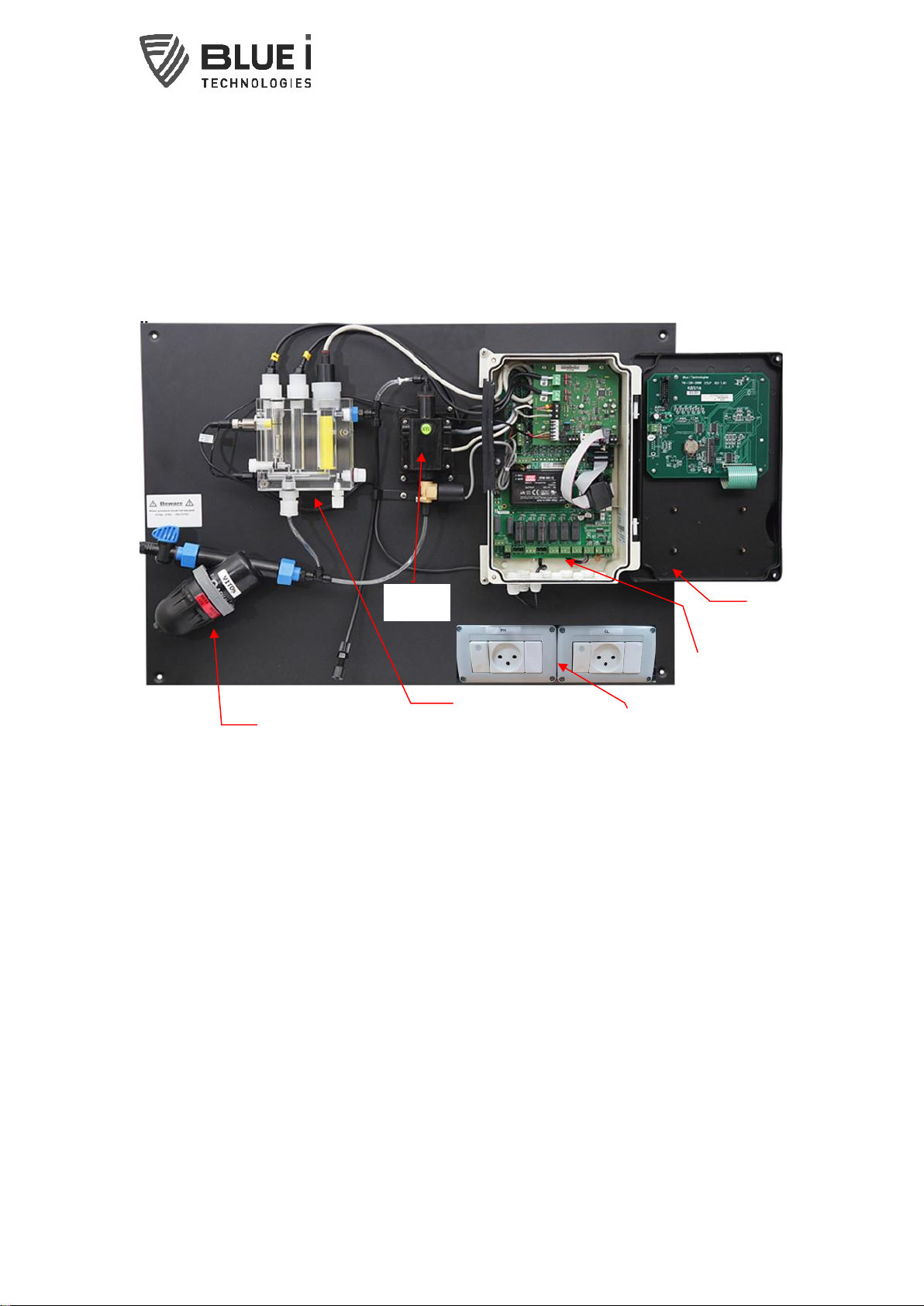
HydroGuard has two primary units: the analyzing unit and the control unit.
The analyzing unit performs the actual measurements and contains the following
components:
Filter –130 micron filter meant as additional protection for the measuring
equipment
Acrylic cell - holds all the electrodes / probes (some are optional): pH, ORP, Free
Chlorine and Temperature
Turbidity Module - Measures turbidity levels
Sockets –powers the dosing systems (dosing systems not included)
The control unit includes the electronics and software that control the
measurements performed in the analyzing unit and the chemical dosing by external
dosing systems. It includes the following components:
7 Water. Quality. Secured.
Control Panel - calculates the measurement results and determines the required
chemical dosing to maintain an appropriate chemical balance and provides data to
devices such as a PC or communicator.
Keyboard Panel - mounted on the cover of the control module, it functions as
HydroGuard’s user interface. The control panel displays current measurements and
indicates alarms. All settings and adjustments are performed through the control
panel.
I/O Module (Input/Output) - holds the relays that control external dosing systems
and power supply.
Note: color of components in the above picture may vary from the actual product
Control Panel
Door
Enclosure and
Electronic
Cards
Acrylic Cell with
Free Cl, pH,
Temperature sensors
Turbidity
module
Filter
Dosing equipment
sockets
8 Water. Quality. Secured.
4Installation
4.1
Selecting a Location
Convenient Access
HydroGuard should be installed where it can be easily viewed and operated by pool
personnel.
Dry Area
It is best to install the HydroGuard in a dry area. The unit includes electronic circuitry
that may short circuit and is susceptible to corrosion over long periods in high
ambient moisture levels.
Pool Chemicals
Pool chemicals can be corrosive to HydroGuard’s electronic circuitry. It is highly
recommended that HydroGuard is not installed adjacent to the pool chemicals
storage area or the dosing systems themselves.
Distance from sampling line
The water sampling line that is tapped into main circulation pipe, feeding the
HydroGuard, should be as short as possible. A long sample line from the main
circulation pipe to HydroGuard creates an unnecessary delay between supply,
measurement, analysis, and chemical dosing.
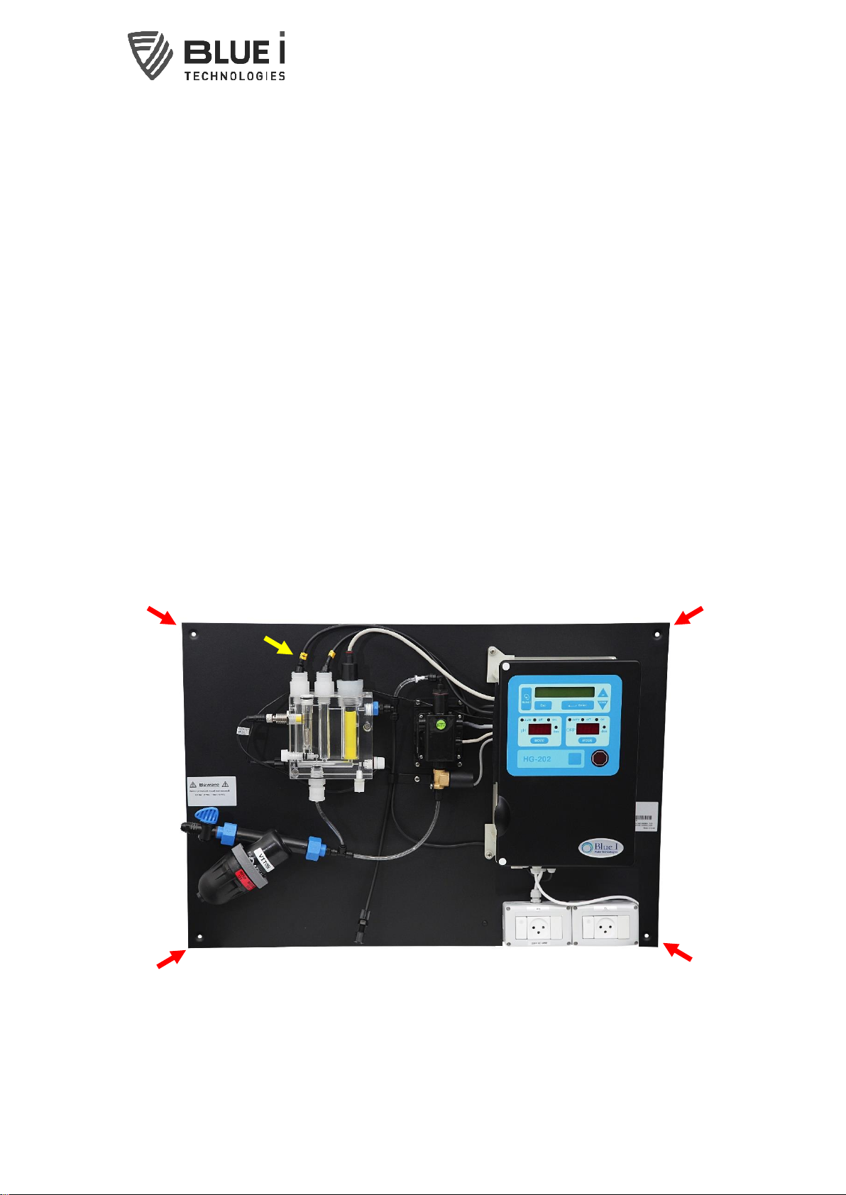
4.2
Mounting the controller and connecting the electrodes
Mounting the controller
Hold the controller (with use of a level) up against the mounting surface upon which
you wish to place the controller and mark the drilling locations through the locations
marked by the red arrows in the above picture.
9 Water. Quality. Secured.
Drill four 5/16” holes in the mounting surface and use appropriate items in order to
fasten the controller securely to the wall.
Connecting the electrodes
Once the controller has been mounted, unscrew the chlorine electrode from the flow
cell and remove the electrolyte cap from its tip. Screw back in and tighten by hand.
The pH and ORP electrodes are shipped separately for preservation purposes. After
removing them from their packaging, the electrolyte caps should be removed and the
electrodes screwed in by hand. Next, connect the appropriate cable to the respective
electrode (cables are marked with yellow indicators for recognition, see yellow arrow
in the above picture).
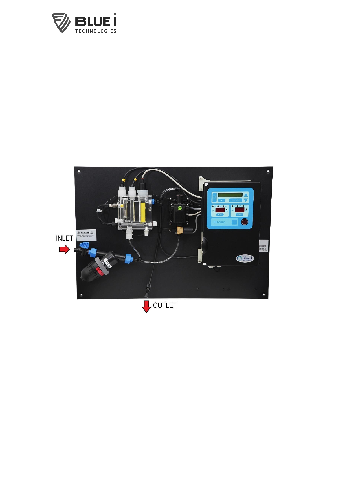
4.3
Plumbing Requirements and Installation
Connect ¼” tubing to inlet and outlet as in the picture above.
HydroGuard requires an inlet water supply and a water return outlet. A shut-off valve
must be installed in the main circulation pump line, between the pump and the
Hydroguard. A ½” OD tube is required from the shut-off valve to the Hydroguard. The
tube should be as short as possible, in order to minimize the delay time between the
pool water being sampled and adjusting dosing levels (see section above). A ½” OD
return line is also required. The distance to the return is not as important as the
distance to the HydroGuard but must return to a lower pressure than the inlet to allow
for sufficient flow.
10 Water. Quality. Secured.
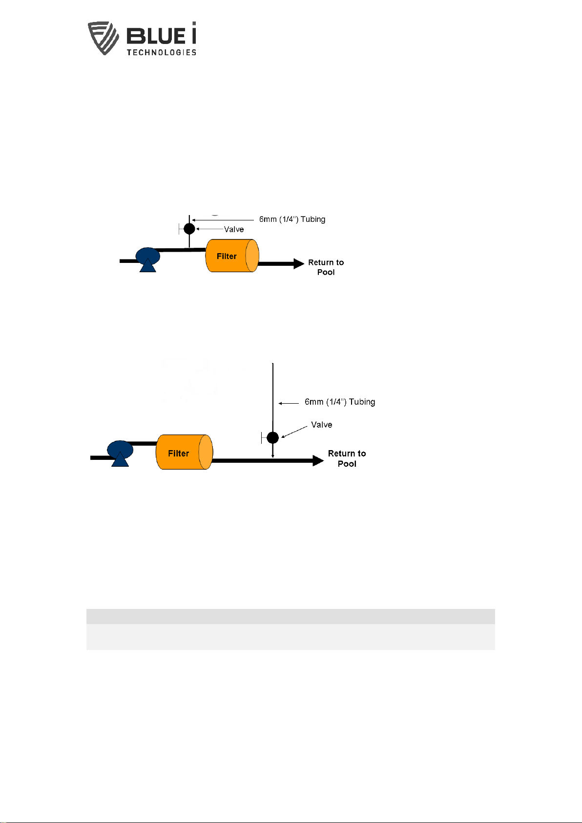
4.3.1 Water Supply
HydroGuard should receive its water supply either directly from the pool, or from the
main circulation pipe between pump and filter. HydroGuard requires a pressurized
water supply to the flow cell. A fitting is supplied for 6mm (1/4”) tubing; however other
tubing and fittings may be attached to the 3/8” FNPT connector. The distance from the
main process pipe should be as short as possible, in order to minimize the delay time
between the water being sampled and HydroGuard testing the water.
Max inlet Pressure: 1 Bar (~15 psi)
Flow Rate: 30-120 L/hr (~0.15-0.6 gpm)
4.3.2 Water Return
The water can be returned to the circulation system at any point with lower pressure
than the water supplied to the HydroGuard. Connect the water return to the ¼” NPT
outlet fitting on the right side of the flow cell.
Return pressure should be at least 0.5 Bar (~psi) below Inlet
Suggested connection scheme
4.4
Electrical Requirements and Installation
HydroGuard requires a 100-240 VAC, 50/60 Hz electrical power source on a separate
16A circuit in the plant room’s electrical board. The main HydroGuard power supply
should be connected to a non-dependent power supply, so that the unit remains
powered constantly. Any relays used to directly activate equipment should be
powered by a dependent power supply (interlocked power supply).
CAUTION
Before making a connection to a power source, confirm that both jumpers are
located on the correct voltage and that the appropriate fuse is in place.
1) Verify that the power switch or circuit breaker to the non-dependent power
source is off.
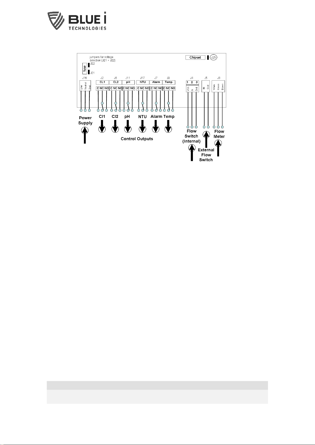
2) Connect the line (live) wire to the I/O board connector marked Line.
3) Connect the neutral wire to the I/O board connector marked Neutral.
4) Connect the earth wire to the I/O Module connector marked Ground.
5) Continue with the other electrical connections.
To Water Inlet
From Water Outlet
11 Water. Quality. Secured.
6) Turn on electrical power only after all electrical connections have been
completed.
4.4.1 NTU card Electrical Installation
1) Install the NTU card on the inside, bottom of the control panel door using the
supplied screws.
2) Connect the NTU card to the I/O module using the supplied ribbon cable and any
open connector (the connectors on both boards operate in parallel).
4.4.2 Input Switches
Flow input switches provide additional layers of security against accidental chemical
additions when there is no flow. If a connection is expected but not detected at each
input, the controller will indicate an alarm and will open all relays (and close the
alarm relay).
Two flow switches and one flow meter may be connected:
Flow Switch (internal): Flow switch connected to flow cell of analyzer. Supports
both 2 and 3 wire flow switches.
oIf a 2 wire switch is used, it should be connected to the “In” and “GND”
connections.
oIf a 3 wire switch is used, the “VCC” connection will also be used.
External Flow Switch: Connection for external 2-wire flow switch. If an external
switch is not connected, a jumper must be installed for the analyzer to operate
properly.
Flow Meter: Connection for 2 or 3 wire flow Meter. The analyzer will not look for
the flow meter connection unless the option is turned ON in technician menu;
therefore, no jumper is required if a meter is not installed.
It is highly recommended for an external flow switch or flow meter to be installed on
the main pipe line.
NOTE
A flow switch is attached to the water inlet of the acrylic cell. This flow switch
determines if enough water is reaching the HydroGuard and adds a layer of safety
12 Water. Quality. Secured.
against chemical additions to a pool in the case of no flow; however, this flow switch
alone does not eliminate the need for additional safety equipment on the dosing
systems directly.
CAUTION
Electrical connections in this section are ONLY recommendations. All electrical
connections should comply with National Electrical code (NEC) and all local
regulations.
4.5
Wiring to Dosing Systems
HydroGuard controls chemical dosing systems using a series of electronic relays
that start and stop the dosing pumps. Each relay opens and closes a switch that
activates a separate pump or piece of equipment.
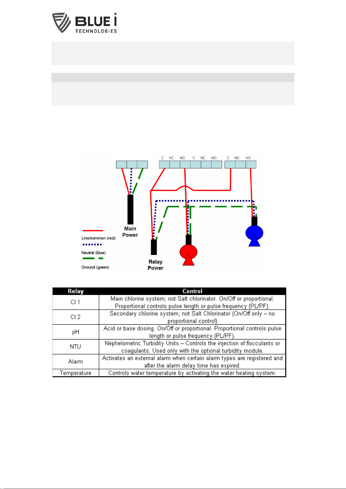
The following table lists the relays and the systems that they activate:
4.5.1 Wiring the Turbidity Relay
Turn off all power supplies to the controller.
Wiring of the NTU (turbidity relay) is identical to wiring of all other relays and should
be connected to a pump-dependent (interlocked) power supply.
The line (live) wire of the pump-dependent power source connects to the connection
labeled Common on the NTU relay. The line wire of the controlled external turbidity

13 Water. Quality. Secured.
equipment is connected to the normally open (NO) or normally closed (NC) connection
of each relay as appropriate. Normally Open means that the relay will be open (i.e. no
power from the relay) until the controller calls for power; Normally Closed means that
the relay will be closed (i.e. power from the relay) until the controller calls to stop
power.
3) Verify that the power switch or circuit breaker to the pump-dependent power
source is off.
4) Connect the earth ground wire of the power supply to the ground return wire from
the controlled external turbidity equipment.
5) Connect the neutral wire of the power supply to the neutral wire from the
controlled external turbidity equipment.
6) Connect the line (live) wire of the power supply to the connector marked ‘C’
(common) on the NTU terminal block.
7) Connect the line (live) wire of the controlled external turbidity equipment to the
normally open (NO) or normally closed (NC) connection on the NTU terminal block.
14 Water. Quality. Secured.
5First Time Operation and Calibration
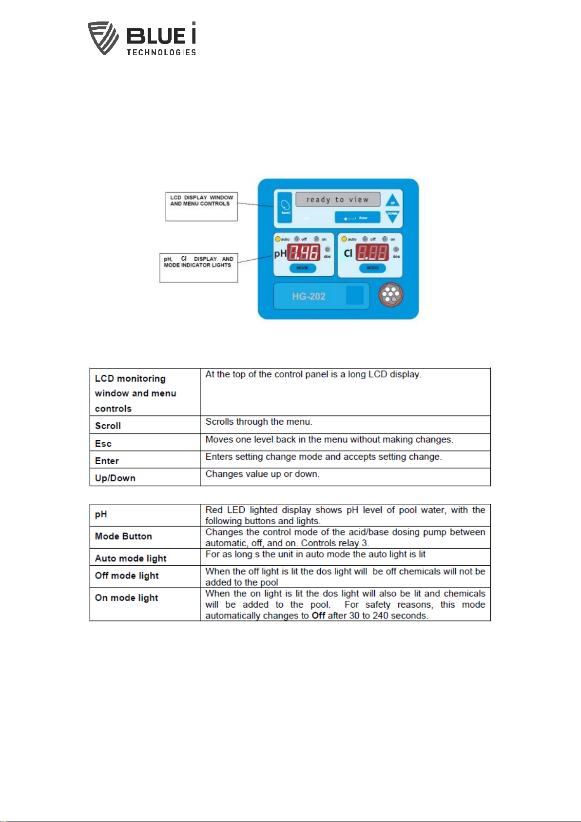
5.1
HydroGuard Control Panel
The HydroGuard control panel, displayed below, is a simple, intuitive interface for
monitoring and controlling pool water quality.
The control panel is separated into several distinct areas:
15 Water. Quality. Secured.
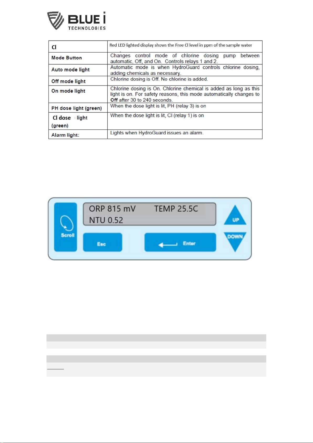
LCD Display
The LCD display in the HydroGuard control panel displays current water conditions in
two rows of data. The top data row displays the water temperature and the ORP
reading. The bottom row shows the Turbidity reading. When an alarm is issued, the
bottom row toggles between the turbidity displays the alarm.
5.2
Menus and Settings
HydroGuard has two menu levels: Operator and Technician. The Operator menu
includes settings that may be controlled by on-site operators. The Technician menu
includes settings and calibrations that should be restricted to specially trained
HydroGuard maintenance technicians. Each menu has a separate password. The
technician level password may be used whenever a password is required, however
the operator password will only be accepted in the operator menu.
NOTE
The default Operator Password is: 123 and the default Technician Password is: 456.
CAUTION
Do not forget your password! There is no way to reset the technician password
without a complete reprogramming of the HydroGuard System.

16 Water. Quality. Secured.
5.2.1 Configuration Setting
Each of the parameters in the operator menu is configured in the same way. The
following procedure describes how to configure a typical setting:
8) Locate the desired parameter in the menu:
9) Press SCROLL until the desired parameter name appears in the LCD display.
10) Press ENTER. “Enter Password 100” appears in the LCD display.
11) Enter the Operator password (or technician password; both are accepted) by
pressing the up arrow or down arrow until the password number is reached.
NOTE
Holding SCROLL why pressing up or down will advance the first digit. Holding up
or down for an extended period of time will proceed through the numbers more
quickly.
12) Press ENTER to accept the password. The parameter name and current setting
appear in the LCD display.
13) Press ENTER, again. The LCD display shows the parameter and the current
setting.
14) Enter the new parameter setting:
15) Press the up arrow or down arrow until the desired value is reached.
16) The second row of the menu display, below the value that is being changed,
shows the current value.
17) Press ENTER to save the new setting or ESC to abort without saving the new
setting.
To change the settings of additional parameters, press Menu until the desired
parameter appears in the LCD display and repeat steps 6-8 above to set the new
parameter.
5.2.2 Technician’s Menu
Configuring each of the technician menu settings is similar to configuring settings in
the Operator menu:
To enter the Technician menu, press (Scroll) and then the up arrow and down arrow
together simultaneously (+) until the menu display changes.
18) Locate the desired parameter in the menu:
19) Press (Scroll) until the desired parameter name appears in the LCD display.
20) Press (Enter). “Enter Password 100” appears in the LCD display.
21) Enter the Technician menu password:
A. Press the up arrow or down arrow until the password number is reached.
B. Press (Enter)
The parameter name and current setting appear in the LCD display.
22) Continue changing the parameter setting, as described in the Operator menu.
23) To set up turbidity measurement, press Scroll until “Turbidity ON/OFF” appears in
the display and press enter.
a) Enter the technician password and press enter.
b) Press up to turn the turbidity sensor on and press enter.
c) Press Scroll until “Turbidity Wiper Interval” appears in the display and press
enter.
d) Enter the technician password and press enter.

17 Water. Quality. Secured.
e) Enter the wiper interval (2 minutes is recommended) and press enter.
f) The turbidity unit should now be active. Confirm that the turbidity value
appears on the LCD display. If it is not active, perform a system reset.
5.2.3 Operation Checklist
Before leaving the site, perform the procedure in this section and record the
requested values.
24) Calibrate the following HydroGuard parameters: pH, ORP, Turbidity
25) Perform the following tests:
a) Press the pH Mode button on the control panel to change the mode to On.
b) Check that the dosing system is adding acid or base chemicals to the pool
water.
c) Press the pH Mode button on the control panel to return the pH mode to Auto.
d) Press the Cl Mode button on the control panel to change mode to On.
e) Check that the dosing system is adding chlorine to pool water.
f) Press the Cl Mode button on control panel to return chlorine mode to Auto.
g) Turn off the main circulation pump.
h) Check that the dosing systems are not adding any chemicals to the pool
water.
26) If the NTU (turbidity) relay is connected to external equipment:
a) Press Scroll until “Turbidity Set Point” appears on the display and press
enter.
b) Enter the operator or technician password and press enter.
c) Enter the turbidity set point value and press enter.
27) With or without the NTU (turbidity) relay connected to external equipment:
a) Press Scroll until “Turbidity High Alarm” appears on the display and press
enter.
b) Enter the operator or technician password and press enter.
c) Enter the turbidity high alarm value and press enter.
5.2.4 Turbidity Relay and External Equipment Operation
The relay will operate in an ON/OFF mode. Whenever the measured turbidity is below
the set point, the relay will remain open (no power to normally open connection).
Whenever the measured turbidity is above the turbidity set point, the relay will close
(power will be supplied to the normally open connection).
If the measured turbidity is above the turbidity high alarm, the alarm on the controller
will be activated. The NTU relay will remain closed (power to the normally open
connection) even during alarm.

18 Water. Quality. Secured.
6Calibration
Parameters must be calibrated with measurements taken with external testing
devices. Always use digital calibration devices, not the less accurate visual test kits.
Alternatively, standard solutions may be used. Make sure the standard solution is
not expired or contaminated prior to using. Follow the procedures below EXACTLY
as instructed.
CAUTION
ALWAYS take water for calibration from the sampling valve, NOT from the process
line directly. The analyzer should always be calibrated with water from the same
source.
6.1.1 pH Calibration
pH is calibrated using a Phenol Red or Buffer 7 solution.
28) Shut off the water inlet and outlet from the flow cell
29) Remove the pH sensor and temperature probe from the flow cell.
30) Wipe sensor probe with a dry cloth and submerge it and the (PT-100)
temperature probe into a cup with the Phenol Red or Buffer 7 solution and wait
for the reading to stabilize.
NOTE
The reading will not stabilize if the temperature probe is not also in the buffer
solution
31) Press (Scroll) until “pH Calibrated”appears in the LCD display.
32) Press (Enter).
33) Enter the password. Press the up arrow or down arrow until the password is
reached.
34) Press (Enter).
35) Press (Enter) again.
36) Press the up arrow or down arrow until the value is the same as the value printed
on the label of the Phenol Red or Buffer 7 Solution.
37) Press (Enter) to save the new calibration or (Esc) to abort without saving.
38) Press (Esc) to return to the main display.
NOTE
pH and Redox (ORP) sensors tend to be slightly erratic in the first 24 hours they
operate. If the above calibrations are performed immediately after these sensors are
installed or replaced, repeat the calibration procedure in approximately 24 hours.
The (PT-100) temperature probe provides grounding and stabilizes the pH and ORP
readings.

19 Water. Quality. Secured.
6.1.2 ORP Calibration
ORP is calibrated using an ORP Standard Solution. A standard closest to the normal
operating value should be used for calibration.
39) Shut off the water inlet and outlet from the flow cell
40) Remove the ORP sensor and (PT-100) temperature probe from the flow cell.
41) Wipe sensor probe with a dry cloth and submerge it and the temperature prove
into a cup with the ORP Standard Solution and wait for the reading to stabilize.
NOTE
The reading will not stabilize if the temperature probe is not also in the buffer
solution
42) Press (Scroll) until ORP Calibrated to appears in the LCD display.
43) Press (Enter).
44) Enter the password. Press the up arrow or down arrow until the password is
reached.
45) Press (Enter).
46) Press (Enter) again.
47) Press the up arrow or down arrow until the value is the same as the value
printed on the label of the standard solution.
48) Press (Enter) to save the new calibration or (Esc) to abort without saving.
49) Press (Esc) to return to the main display.
6.1.3 Chlorine/Turbidity Calibration
50) Take a sample of water from the flow cell
51) Take a reading using a calibrated handheld instrument
52) Press (Scroll) until the relevant menu appears in the LCD display.
53) Press (Enter).
54) Enter the password. Press the up arrow or down arrow until the password is
reached.
55) Press (Enter).
56) The value that appears is the last calibrated value.
57) Press (Enter) again.
58) Press the up arrow or down arrow until the value is the same as the handheld
instrument
59) Press (Enter) to save the new calibration or (Esc) to abort without saving.

20 Water. Quality. Secured.
60) Press (Esc) to return to the main display.
NOTE
When the HydroGuard is initially turned on, the pH and ORP readings will continue to
rise for the first 24-48 hours. If calibration is required, it is best to recalibrate when
the readings have stabilized.
Table of contents
Other Blue I Measuring Instrument manuals


Popular Measuring Instrument manuals by other brands


janitza
janitza UMG 604-PRO User manual and technical data

Lighthouse Worldwide Solutions
Lighthouse Worldwide Solutions ApexZ Operator's manual

ST
ST Beta 20P Series operating manual

VOLTCRAFT
VOLTCRAFT VC-330 operating instructions

LaMotte
LaMotte SMART3 Operator's manual

PCB Piezotronics
PCB Piezotronics IMI SENSORS M629A31 Installation and operating manual