BLUE JAY BJ-194Z User manual

User Manual
Tel: +0086-023-67628702 Email:tech@cqbluejay.com
www.cqbluejay.com
Add: 1802,Building 2,No.88,Jianxin East Road,Chongqing,400020,China
BJ-194Z
Multi-function Power Meter
User Manual
Version:1.5
Revision 2022-8

User Manual
Tel: +0086-023-67628702 Email:tech@cqbluejay.com
www.cqbluejay.com
Add: 1802,Building 2,No.88,Jianxin East Road,Chongqing,400020,China - 1 -
Read me
When you use BJ-194… series multi-function meter, be sure to read this user manual
carefully, and be able to fully understand the implications, the correct guidance of
operations in accordance with user manual, which will help you make better use of BJ-194…
series multi-function meter, and help to solve the various problems at the scene.
1. Before the meter turning on the power supply, be sure that the power supply within the provisions
of the instrument;
2. When installation, the current input terminal must non-open, voltage input terminals must Non-
short circuit;
3. Communication terminal (RS232/RS485 or Ethernet) is strictly prohibited to impose on high
pressure;
4. Be sure the instrument wiring consistent with the internal system settings;
5. When communicating with the PC, instrument communication parameters must be consistent
with the PC.
●Please read this user manual carefully
●Please save this document

User Manual
Tel: +0086-023-67628702 Email:tech@cqbluejay.com
www.cqbluejay.com
Add: 1802,Building 2,No.88,Jianxin East Road,Chongqing,400020,China - 2 -
Directory
1. - SUMMARIZE ............................................................................................................................................ - 3 -
2. - FEATURES................................................................................................................................................. - 4 -
2.1. - ELECTRICITY METERING .........................................................................................................................- 4 -
2.2. – SPECIFICATIONS......................................................................................................................................- 5 -
3. - INSTALLATION AND START-UP .......................................................................................................... - 7 -
3.1.- INSTALLATION..........................................................................................................................................- 7 -
3.2. - CONNECTION TERMINAL.........................................................................................................................- 9 -
3.3. – TYPICAL WIRING (3P4W).....................................................................................................................- 10 -
4. - SCREEN DISPLAY ..................................................................................................................................- 11 -
4.1.- FULL SYMBOL IN DISPLAY SCREEN ........................................................................................................- 11 -
4.2.- INTRODUCTION OF SCREEN PAGES.........................................................................................................- 12 -
5. - OPERATION MODE .............................................................................................................................. - 13 -
6. - SETUP PROCEDURE............................................................................................................................. - 14 -
6.1.- ENTER SETUP MENU ..............................................................................................................................- 14 -
6.2. - INPUT SIGNAL SETUP ............................................................................................................................- 15 -
6.3. - COMMUNICATION PORT SETUP..............................................................................................................- 16 -
6.4. - DIGITAL OUTPUT SETUP ........................................................................................................................- 17 -
6.5. - SYSTEM SETTING ..................................................................................................................................- 20 -
7. - PULSE OUTPUT ..................................................................................................................................... - 21 -
8. - COMMUNICATION INTERFACE ....................................................................................................... - 22 -
8.1.- CONNECTION FOR RS485 BUS ..............................................................................................................- 22 -
8.2.- MODBUS © PROTOCOL........................................................................................................................- 23 -
8.3.- REGISTER MAP ......................................................................................................................................- 24 -
8.3.1.- Basic power data—Primary Side.................................................................................................. - 24 -
8.3.2.- Basic power data—Secondary Side .............................................................................................. - 25 -
8.3.3.- Meter status data .......................................................................................................................... - 25 -
8.4.- EXAMPLE ...............................................................................................................................................- 26 -
9. - SAFETY CONSIDERATIONS ............................................................................................................... - 27 -
10. - MAINTENANCE ................................................................................................................................... - 27 -
11. - TECHNICAL SERVICE ....................................................................................................................... - 28 -

User Manual
Tel: +0086-023-67628702 Email:tech@cqbluejay.com
www.cqbluejay.com
Add: 1802,Building 2,No.88,Jianxin East Road,Chongqing,400020,China - 3 -
1. - SUMMARIZE
BJ-194Z Multi-Function Power Meter is a LCD screen electrical panel power meter. It is the ideal
choice for monitoring and measuring of 3P4W or 3P3W power systems.
It can measure all of the power parameters in power grid:
Current,
Voltage,
Frequency,
Active power,
Reactive power,
Apparent power,
Energy (Active/Reactive),
Power factor,
With optional expansion modules, it can also transmit the parameter into 2*Relay output (2DO) and
4*Switch input (4DI). For transformers, generators, capacitor banks and motors of the distributed
detection, automatic control system, on-line monitoring display.
It can replace the traditional analog or many digital measurement instruments (such as ammeter,
voltmeter, power meter, power factor meter, frequency meter, etc.) with the advantages of improving
system reliability, making the on-site wiring convenient and reduce system cost.
With serial port, BJ-194Z can connect with PC; and use Modbus to set programming and read the
data. Based on this power meters, you can simply set up a monitoring system with the IPC and
central software.
APPLICATIONS
-. All power parameter measurement;
-. Energy Measurement and electrical fire monitor and control;
-. Replacing the three-phase power meter, three phase electricity transmitter;
-. Transformers, generators, capacitors and electric motors distributed detection;
-. Medium and low pressure systems;
-. SCADA, EMS, DCS integrators.

User Manual
Tel: +0086-023-67628702 Email:tech@cqbluejay.com
www.cqbluejay.com
Add: 1802,Building 2,No.88,Jianxin East Road,Chongqing,400020,China - 4 -
2. - FEATURES
2.1. - Electricity Metering
By means of an internal microprocessor it simultaneously measures:
Parameter
Symbol
A-phase
B-phase
C-phase
Total
Phase-line voltage
V
x
x
x
/
*Phase-phase voltage
V
x
x
x
/
Current
A
x
x
x
/
Frequency
Hz
/
/
/
x
Power factor
Cos Φ
xx
xx
xx
x
Active power
W
x
x
x
x
Reactive power
Var
x
x
x
x
Active energy
Wh
x
x
x
x
Reactive energy
Varh
x
x
x
x
4-quadrant electric data
x
x
x
x
Note: Phase-phase voltage is Uab, Ubc, Uca, voltage data determined by the different wiring
Available: x: Display and communications.
xx: Only can read in RS485 communication
The BJ-194Z delivers the visualization of parameters listed above by means of LCD type
displays. In the main display area shows 4 power parameters, with other display area show the
various parameters and state of meter on each page jump. For more details of measurement
parameters please refer to the subsequent for displays introduction and RS485 communication
instructions.
OTHER FEATURES
- Low-size (96 x 96 mm), panel-mounting meter.
- True R.M.S. measuring system.
- Instantaneous, maximum and minimum values of each measured parameter.
- Energy measurement (indication through a lighting led)
- RS-485 or Ethernet(optional) type communication to a PC.

User Manual
Tel: +0086-023-67628702 Email:tech@cqbluejay.com
www.cqbluejay.com
Add: 1802,Building 2,No.88,Jianxin East Road,Chongqing,400020,China - 5 -
2.2. – Specifications
- Reference standard:
Basic electricity: IEC 61557-12:2010
Active energy: IEC 62053-21:2010
Reactive energy: IEC 62053-23:2010
- Accuracy standards
Parameter
Accuracy
A phase
B phase
C phase
All
Voltage
Current
Active Power
Reactive Power
Apparent power
Power Factor
Active Energy
Reactive Energy
Frequency
0.5
0.5
0.5
0.5
0.5
0.5
1.0
2.0
0.05
V1
A1
W1
var1
VA1
PF1
V2
A2
W2
var2
VA2
PF2
V3
A3
W3
var3
VA3
PF3
W
var
VA
PF
Wh
varh
Hz
- Input
Voltage: Rated 300V L-N, (optional 100V L-N)
Current: Rated 5A (optional 1A)
Frequency: 45-65Hz
- Load
Voltage: <0.1VA / phase (rated 220V)
Current: <0.4VA / phase (rated 5A)
- Overload
Current: 1.2 times rated continuous; 1 seconds for 10 times the rated
Voltage: 1.2 times the rated continuous; 10 seconds for 2 times the rated
- Dielectric strength
IEC / EN 61010-1:2010
2kV AC RMS 1 minute, between input / output / case / power supply

User Manual
Tel: +0086-023-67628702 Email:tech@cqbluejay.com
www.cqbluejay.com
Add: 1802,Building 2,No.88,Jianxin East Road,Chongqing,400020,China - 6 -
- EMC Test
Standard
Test voltage
Electrostatic discharge immunity
test
IEC-61000-4-2
level 4
8KV
Electrical fast transient burst
immunity test
IEC61000-4-4
level 3
Input 1kV; Power supply 2kV
Surge (Shock) immunity test
IEC61000-4-5
level 4
common mode test voltage
4kV
- Work environment
Temperature: -20°C ~ +60°C
Humidity: RH 20% ~ 95%(No condensation)
- Protection
Panel: IP54
Case: IP20
- Storage Conditions
Temperature: -25°C ~ +70°C
Humidity: RH 20% ~ 95%
- Working Power
AC/DC 90-240V, 45-65Hz
DC 20-60V (Optional)
Maximum power consumption 6W
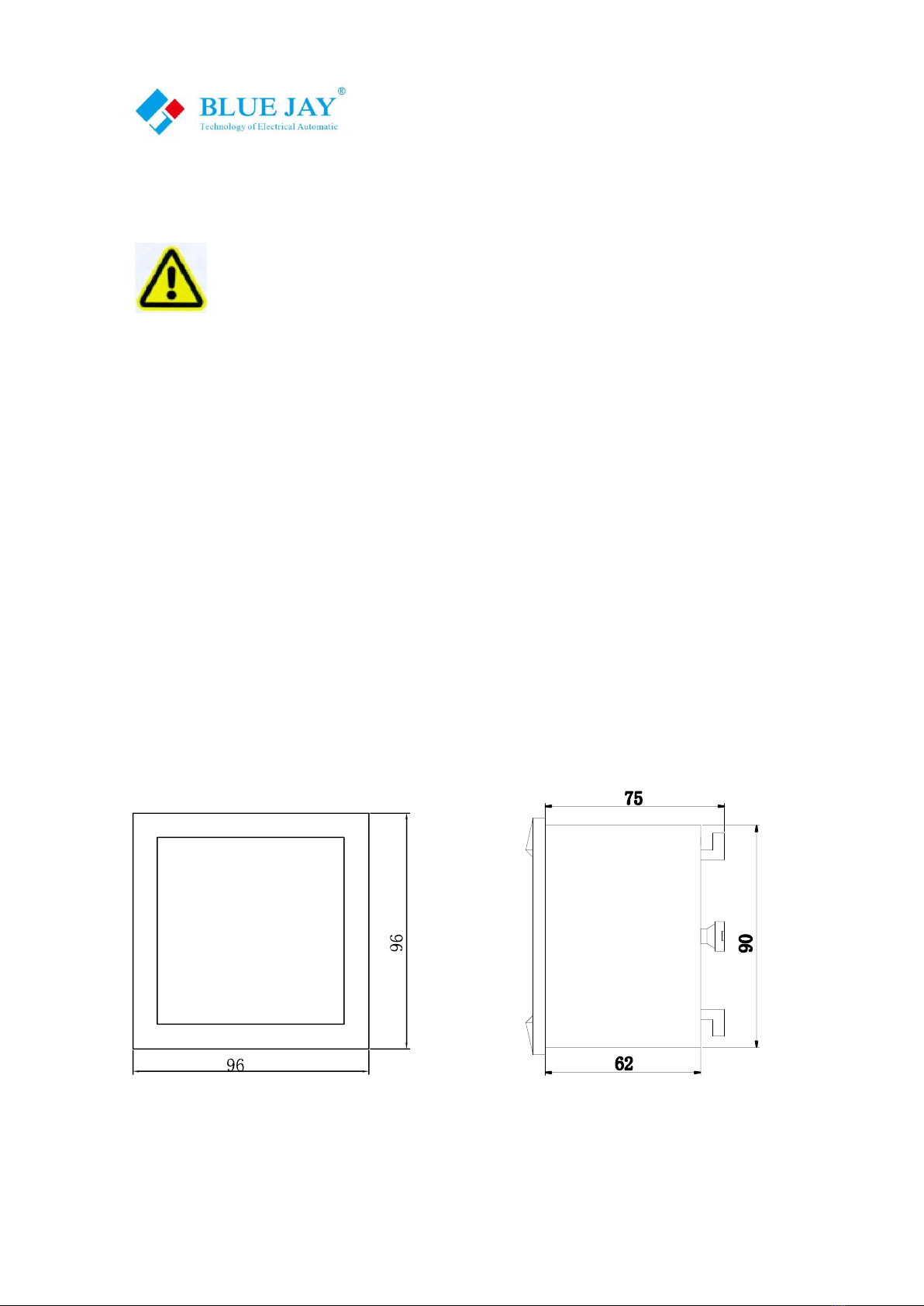
- Dimensions
L × W × H =96mm×96mm×71mm
- Installation hole size
L × W = (91+0.8mm) × (91+0.8mm)
User Manual
Tel: +0086-023-67628702 Email:tech@cqbluejay.com
www.cqbluejay.com
Add: 1802,Building 2,No.88,Jianxin East Road,Chongqing,400020,China - 7 -
3. - INSTALLATION AND START-UP
The manual you hold in your hand contains information and warnings that the user
should respect in order to guarantee a proper operation of all the instrument functions
and keep it in safety conditions. The instrument must not be powered on and used until
its definitive assembly is on the cabinet’s door.
If the instrument is not used as manufacturer’s specifications, the protection of the
instrument will be damaged.
When any protection failure is suspected to exist (for example, it presents external visible
damages), the instrument must be immediately powered off. In this case contact a qualified
service representative.
3.1.- Installation
Mounting
Instrument is to be mounted on panel (cut-out 91+0.8 x 91+0.8 mm). Keep all connections
into the cabinet.
Please note that with the instrument powered on, the terminals could be dangerous to touch
and cover opening actions or elements removal may allow accessing dangerous parts.
Therefore, the instrument must not be used until this is completely installed.
Front view Side view

User Manual
Tel: +0086-023-67628702 Email:tech@cqbluejay.com
www.cqbluejay.com
Add: 1802,Building 2,No.88,Jianxin East Road,Chongqing,400020,China - 8 -
Notes:
Input signal: BJ-194… series using a separate acquisition calculate for each measurement channel, to ensure
consistent in use, for different load forms, it's a variety of connection mode. Access wire shall be met: the current
2.5 square mm, voltage of 1.5 square millimeters.
Voltage input:
Input voltage should not exceed the rated input voltage products (120Vac or 450Vac),
Otherwise, you should use external CT. Suggest 1A fuse be installed in the voltage input side.
Current Input:
Standard input current is 5A, if greater than 5A should use external CT.
When the CT is connected with other instruments, make sure wiring methods be used in series.
Before remove the current input connection, must be sure to disconnect the primary circuit or shorted secondary
circuit of CT. In order to facilitate disassembly, please do not connect to CT directly, and the terminal block is
suggested.
Sequence of wire:
Please make sure that the input voltage and current corresponding to the same phase sequence, and the same
direction; Otherwise, the Values and symbols will be wrong!! (Power and Energy)
The input network configuration of instrument depends on the CT number of the system:
in the condition of 2 CT, select the three-phase, three-lines two components;
in the condition of 3 CT, select the three-phase, four-lines three component mode.
Instrument connection mode, set of the instrument (programming input network NET) should be the same load
wiring as measured wiring. Otherwise, the measurement instrument will lead to incorrect voltage or power.
In three-phase three-wire mode, the measurement and shows the line voltage;
In three-phase four-wire mode, the measurement and shows the phase voltage.
Auxiliary power:
BJ-194… series with universal (AC / DC) power input, if not for a special statement, we provide the 220VAC/DC
or 110VAC/DC power interface for standard products. Instruments limit work power supply: AC / DC: 90-240V,
please ensure that the auxiliary power can match with BJ-194… series meter to prevent damage to the product.
A. Suggest install 1A fuse in the fire line side.
B. For the areas with poor power quality, suggest install lightning surge suppressor and rapid burst suppressor to
prevent lightning strikes.

User Manual
Tel: +0086-023-67628702 Email:tech@cqbluejay.com
www.cqbluejay.com
Add: 1802,Building 2,No.88,Jianxin East Road,Chongqing,400020,China - 9 -
3.2. - Connection Terminal
Upper connection terminal
15
16
50
49
48
47
60
59
58
2
1
RP-
RP+
AP-
AP+
GUD
RS485B
RS485A
Power supply
47. Active energy pulse output (+)
48. Active energy pulse output (-)
49. Reactive energy pulse output (+)
50. Reactive energy pulse output (-)
1. *Supply voltage input: 0 V
2. *Supply voltage input: 220 Va.c.
58. RS-485 ( + )
59. RS-485 ( - )
60. RS-485 ( GND )
Middle connection terminal
22
21
20
19
70
71
72
73
74
DO2
DO1
COM
DI1+
DI2+
DI3+
DI4+
20. Route 1 digital output (+)
19. Route 1 digital output (-)
22. Route 2 digital output (+)
21. Route 2 digital output (-)
70. Digital input COM pin
71. Route 1 digital input (+)
72. Route 2 digital input (+)
73. Route 3 digital input (+)
74. Route 4 digital input (+)
Lower connection terminal
14
13
12
11
9
8
7
6
5
4
Un
Uc
Ub
Ua
C-phase Current
B-phase Current
A-phase Current
11. Voltage A-phase input
12. Voltage B-phase input
13. Voltage C-phase input
14. Neutral Voltage input
4. Current A-phase - S1 input
5. Current A-phase - S2 input
6. Current B-phase - S1 input
7. Current B-phase - S2 input
8. Current C-phase - S1 input
9. Current C-phase - S2 input
Note:
The terminal pin will change depends on special order requirement; please refer to the sticker on
the meter!

User Manual
Tel: +0086-023-67628702 Email:tech@cqbluejay.com
www.cqbluejay.com
Add: 1802,Building 2,No.88,Jianxin East Road,Chongqing,400020,China - 10 -
3.3. – Typical Wiring (3P4W)
IMPORTANT REMARK!
If power = -0.01 is shown for any of the phases and voltage and current are not zero for this
phase, check out following points:
- Assure that A, B and C phases coincide in voltage and current.
- Correct polarity? Reverse the current transformer placed at this phase.
Note:
This connection drawing is for reference only; the actual connecting terminal please refer to the
label on the rear part.

User Manual
Tel: +0086-023-67628702 Email:tech@cqbluejay.com
www.cqbluejay.com
Add: 1802,Building 2,No.88,Jianxin East Road,Chongqing,400020,China - 11 -
4. - SCREEN DISPLAY
4.1.- Full Symbol in Display Screen
User Manual
Tel: +0086-023-67628702 Email:tech@cqbluejay.com
www.cqbluejay.com
Add: 1802,Building 2,No.88,Jianxin East Road,Chongqing,400020,China - 12 -
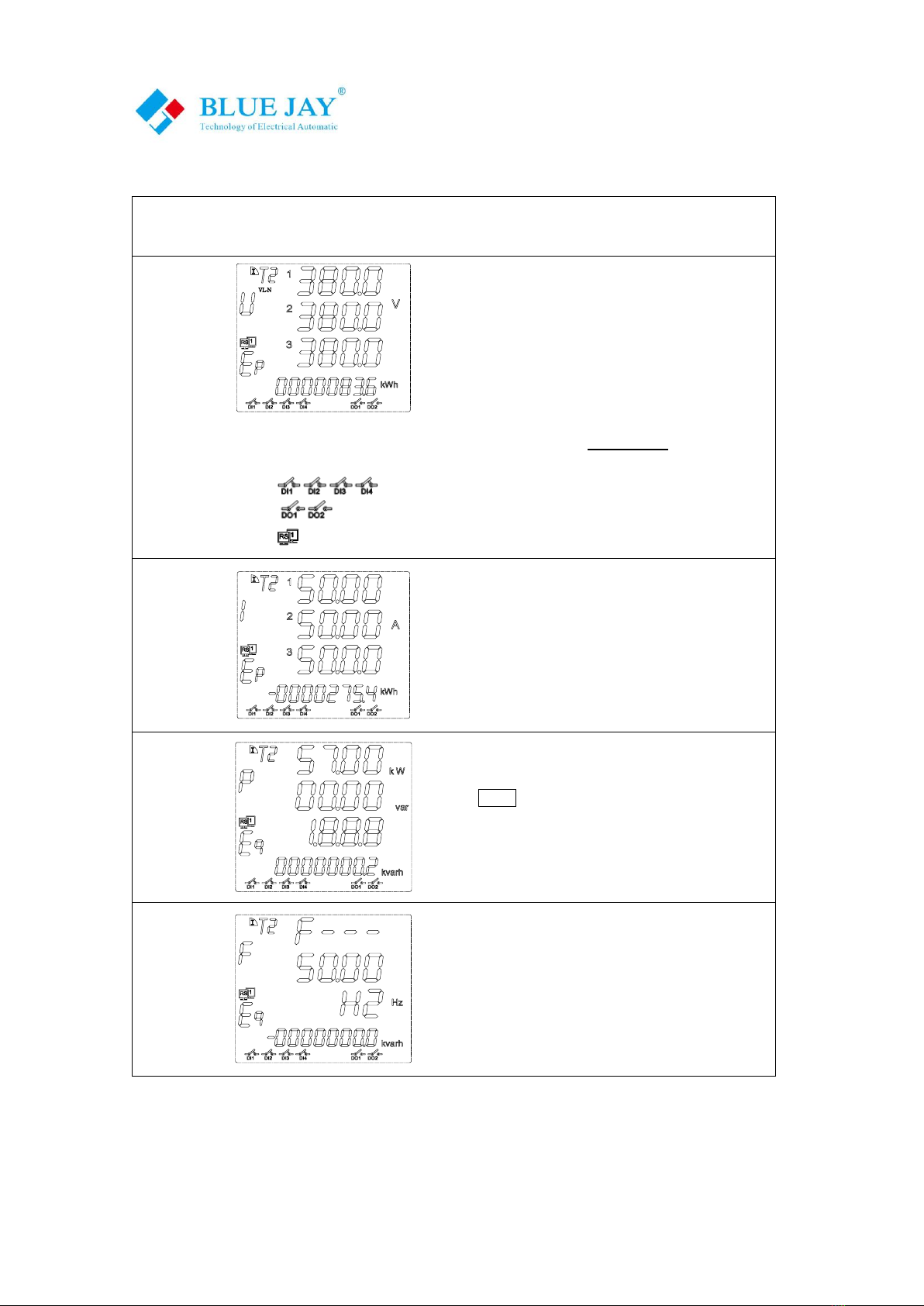
4.2.- Introduction of Screen Pages
Screen
page NO.
Screen interface
Explanation
- 1 -
Three phase voltage Ua, Ub, Uc;
Note: In high voltage measurement, X103 mean the
showing value multiplied by 1000, in the screen
diagram mean the voltage is
10X1,000=10,000volt
Bottom character “Ep” show total active energy is
83.6KWh.
Note: Detail information for each symbol, please refer chapter 5.1, Surround area
shows the system information, in other screen are same:
show DI1, DI2, DI3, DI4 in the closed;
show DO1, DO2 opened;
flicker show Communication Rx/Tx normal;
- 2 -
Three-phase current Ia, Ib, Ic.
Bottom Ep shows total negative active energy.
- 3 -
Total active power, Total reactive power, and Total
factor.
Press can switch to show independent three
phase active (P), Reactive(Q), Apparent power(S)
value
Bottom “Eq” shows total active energy.
- 4 -
Frequency of grid.
Bottom “Eq” shows total negative reactive energy.
Note:
In special requirement order or firmware iteration, the screen may add display pages, please ask
the sales team to get latest manual.

User Manual
Tel: +0086-023-67628702 Email:tech@cqbluejay.com
www.cqbluejay.com
Add: 1802,Building 2,No.88,Jianxin East Road,Chongqing,400020,China - 13 -
5. - OPERATION MODE
When the device is powered up, the entire symbol will be on, and the meter starts to self- test.
After few seconds, the meter is ready for operation and shows firmware, then automatic jump to
The first screen.
In Monitor screen &
Setup sub-menu
press key or , screen will move to previous or next page.
In Setup variables
configuration menu
press can move the setting cursor to left;
press can scroll selection the number 0 ~ 9.
SET
Press this key in monitor screen can call out the password screen;
In other screen used as Exit & roll back to up layer menu.
Press this key in monitor screen can call out the firmware screen;
In Setup menu used as confirm the value entry or jump to down layer menu
Note: In Setup menu, if changed the setting value, press SET for exit menu, device will call out
confirm screen ask “SAVE”
Then press SET exit without saving
press save and exit.

User Manual
Tel: +0086-023-67628702 Email:tech@cqbluejay.com
www.cqbluejay.com
Add: 1802,Building 2,No.88,Jianxin East Road,Chongqing,400020,China - 14 -
6. - SETUP PROCEDURE
The SETUP procedure of the BJ-194Z is performed by means of several SETUP options. There
has a password to protect unexpectedly enter the Setup menu. Once into the Setup menu, use
the keyboard to select different options and enter required variables:
6.1.- Enter Setup Menu
Regular
Monitor
Screen
SET
Input signal setup
Refer to chapter 6.2
Communication port setup
Refer to chapter 6.3
Digital output (relay) port setup
Refer to chapter 6.4
Note: If do not select port, no such pages
System parameter setup
Refer to chapter 6.5
Default password are 0001,
can be modified in SYS sub-
menu
User Manual
Tel: +0086-023-67628702 Email:tech@cqbluejay.com
www.cqbluejay.com
Add: 1802,Building 2,No.88,Jianxin East Road,Chongqing,400020,China - 15 -
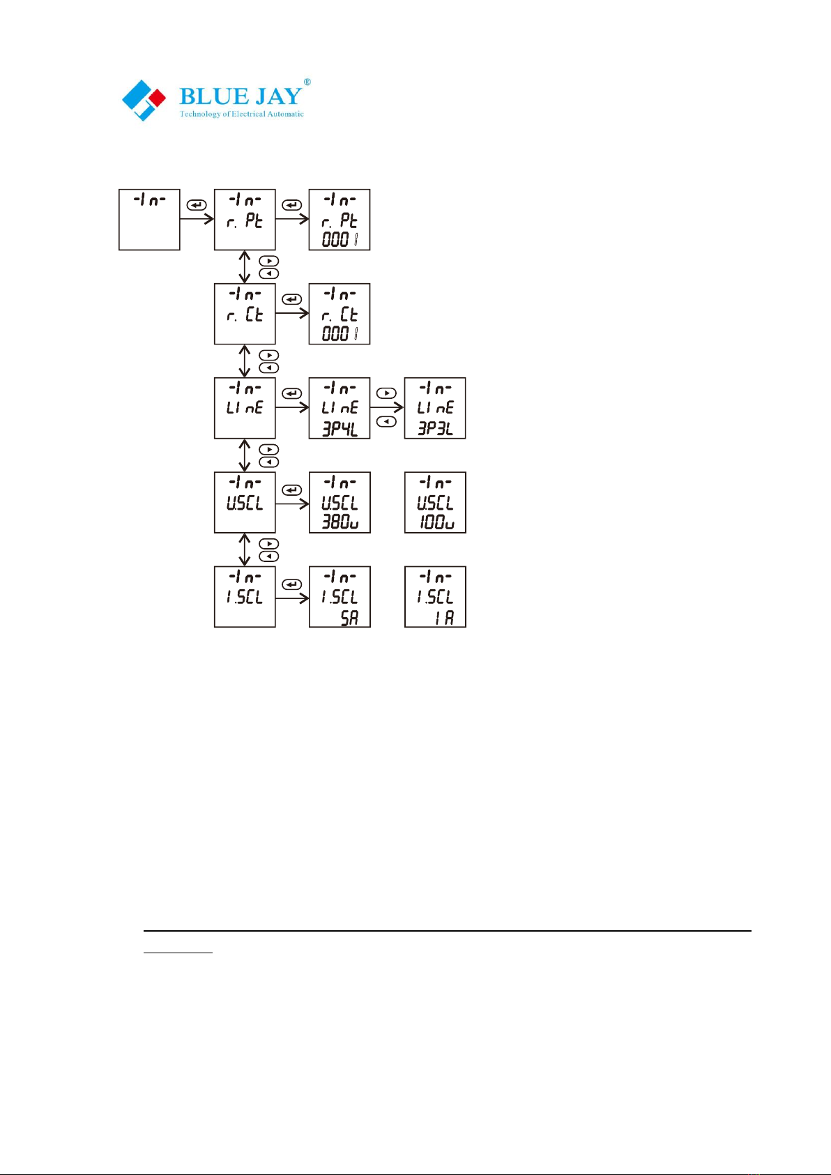
6.2. - Input Signal Setup
or
or
Voltage transformer ratio(1)*
Default 0001
Current transformer ratio(1)*
Default 0001 or based on order requirement
Power grid mode
Default 3P4L(2)*
Rated voltage scale
Default 380V(3)*
Rated current scale
Default 5A
Notes:
(1) In medium or high voltage system, set this value can expand measuring range, values
represent the current transformer (primary side voltage) / (secondary side current). Must set
U.scl in 100V or other specified VT secondary voltage.
(2) If in order specified power grid are 3P3L, Blue Jay will connect Un and Ub terminal internally.
In screen only show phase to phase parameter
(3) Blue Jay calibrate meter under 380V range, high-quality linearity performance ensures that the
meter can accurately measure in the lower voltage range. That can compatible with 120V, 220V,
230V, 240V, 277V system.
If need to use in different voltage scale or different types CT, please contact our sales team for
more help.

User Manual
Tel: +0086-023-67628702 Email:tech@cqbluejay.com
www.cqbluejay.com
Add: 1802,Building 2,No.88,Jianxin East Road,Chongqing,400020,China - 16 -
6.3. - Communication Port Setup
Modbus address (1)*
Default 0001
Comm port baud ratio (2)*
Default 9600 (2)*
Comm port data format
Default n.8.1, can select n.8.1 / E.8.1 / n.8.2
Note:
(1) Modbus address setup range 1-247
(2) Baud ratio can select 1200 / 2400 / 4800/ 9600 / 19200, regular meter equipped communication
port max baud ratio are 19200bps, if need higher speed, please contact Blue Jay sales team.

User Manual
Tel: +0086-023-67628702 Email:tech@cqbluejay.com
www.cqbluejay.com
Add: 1802,Building 2,No.88,Jianxin East Road,Chongqing,400020,China - 17 -
6.4. - Digital Output Setup
DO port is optional module, if do not choose this external port, in Setup menu do not have this sub-
menu, and this chapter are invalid.
When device has more than one DO port, you can set the DO-2, as same step.
The physical DO relay standard is 5A 250VAC / 5A 30VDC
Relay trig threshold, value related to
secondary side
Default 5500 (1)*
Hysteresis (2)*
Default 5500
DO working mode (3)*
Default rn
Remote
Auto Trig
Turned Off
Delay timer of the trig (4)*
Default 0010
Parameter be trigged (5)*
Default are 1A-H
Notes:
(1) Relay trig threshold value have different units:
Voltage - 0.1V
Current - 0.001A
Active power - 0.1W
Reactive power - 0.1VAR
Power factor - 0.001
Frequency- 0.01HZ
(2) Hysteresis value is for prevent unexpected relay release, only the measurement parameter falls
back lower / over a certain difference value from trig threshold, the DO can be released.
Formula: Xm < X - Xr (Upper edge trig) or Xm > X + Xr (Lower edge trig)
Xr = x / 10000
Xm is measurement rms value of electrical parameter
Example: Trig threshold value 3.700A; hysteresis value 0.03; After relay trigged, when

User Manual
Tel: +0086-023-67628702 Email:tech@cqbluejay.com
www.cqbluejay.com
Add: 1802,Building 2,No.88,Jianxin East Road,Chongqing,400020,China - 18 -
measured value Xm < 3.589A (3.700-3.700*0.03), the relay will be released.
(3) DO port preset 2 types of working mode, and can be Turned Off
Auto Trig –When the measurement parameter over or lower the preset , the DO relay
act, terminal of DO+ / DO- shorted. After the measurement parameter fall back to a certain
value can be released relay coil.
Remote - DO relay act by RS-485 control command, user can use function code 05 to trig
single relay, device RS-485 port follow MODBUS-RTU protocol, command as following:
Host inquiry:
01
05
00 01
FF 00
DD FA
Address
Code
No.1 Relay register
Relay value
(FF00:close; 0000: open)
CRC
Slave answer:
01
05
00 01
FF 00
DD FA
(4) In Auto trig mode, after Xm > in the specified delay time, DO relay act. Setting value
from 0.000sec (no delay) to 999.9 sec, default 0010 = 1sec
In Remote mode, if setup value = 0, output is Level type,
If set value = 0, output is Pulse type, value = pulse width
(5) Parameter of the DO can be set, preset 52 types parameter that can be used in auto trig
mode
A phase voltage upper trig
B phase voltage upper trig
C phase voltage upper trig
Any one of Ua / Ub / Uc3 upper trig
A phase current upper trig
B phase current upper trig
C phase current upper trig
Any one of Ia / Ib / Ic3 upper trig
A phase active power upper trig
B phase active power upper trig
C phase active power upper trig
Total active power upper trig
A phase reactive power upper trig
B phase reactive power upper trig
C phase reactive power upper trig
Total reactive power upper trig
A phase apparent power upper trig
B phase apparent power upper trig
C phase apparent power upper trig
Total apparent power upper trig
Total power factor upper trig
Frequency upper trig
DI1 closed trig
DI2 closed trig
DI3 closed trig
DI4 closed trig
Note: If in screen show “XX ” mean lower limit trig, for DI port mean open loop trig
User Manual
Tel: +0086-023-67628702 Email:tech@cqbluejay.com
www.cqbluejay.com
Add: 1802,Building 2,No.88,Jianxin East Road,Chongqing,400020,China - 19 -
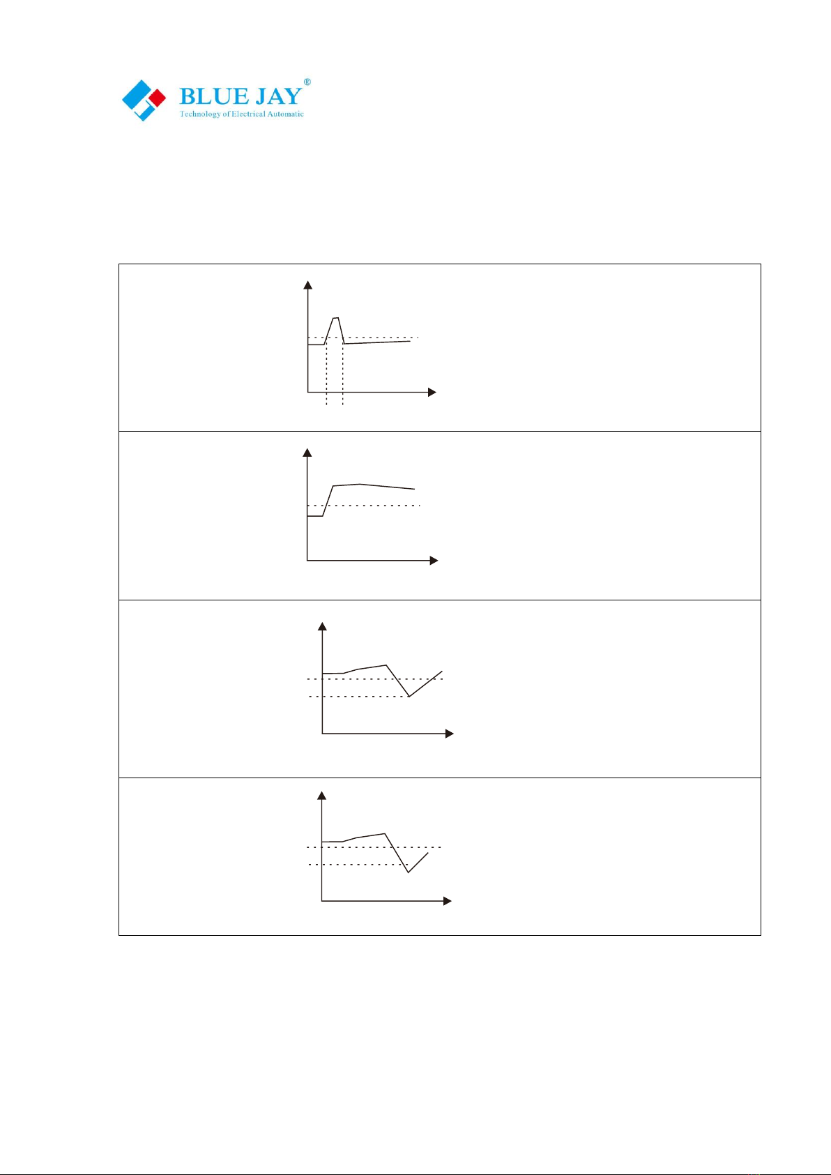
* Delay & Hysteresis logic
Example in upper limit alarm of A phase voltage:
U-d mean detected Ua
U-set mean Alarm value of A phase
Alarm will not trigged
Ua
T
U-set
Δt
U-d
If Δt < Delay setting value,
The Alarm will not trig, that can avoid influence of
the transient electrical parameters
Alarm trigged
Ua
T
U-set
U-d
When U-d over U-set, and after delay setting time
cool down, the value still over U-set, the alarm
trigged
Alarm will not
released
Ua
T
U-set
Δt
ΔU
U-d
If ΔU < Hysteresis value
The Alarm will not release, that can avoid influence
of parameter unexpected fluctuations
Alarm released
Ua
T
Δt
ΔU
U-d
U-set
When U-d lower than
(U-set -Hysteresis)
The Alarm will release
Table of contents
Other BLUE JAY Measuring Instrument manuals


Popular Measuring Instrument manuals by other brands


JDS Uniphase
JDS Uniphase WiFi Advisor user guide

Measure-Quip
Measure-Quip AAVM-318 instruction manual

WEHRLE
WEHRLE WECOUNT-S operating instructions

Preferred
Preferred JC-10D2 Installation & operation instructions

Fieldpiece
Fieldpiece EH4W Operator's manual

Würth
Würth Flex 400 Translation of the original operating instructions


