Blue point MagicLift YA642C Instructions for use
MagicLift™ Hydraulic Service Jacks
Printed in China
YA642C-M0 _092015
Read this manual and follow all the Safety Rules and Operating Instructions before using this product.
Model
YA642C
SFA Companies
http://www.omegalift.com
Capacity
2-1/2 Ton
This is the safety alert symbol. It is used to alert you to potential personal injury hazards.
Obey all safety messages that follow this symbol to avoid possible injury or death.
!
!WARNING
To avoid crushing and related injuries:
NEVER work on, under or around a
load supported only by a hydraulic
jack. ALWAYS use adequately rated
jack stands.
U.S Patent No.s 5,755,099/5,946,912
Operating Instructions & Parts Manual
2
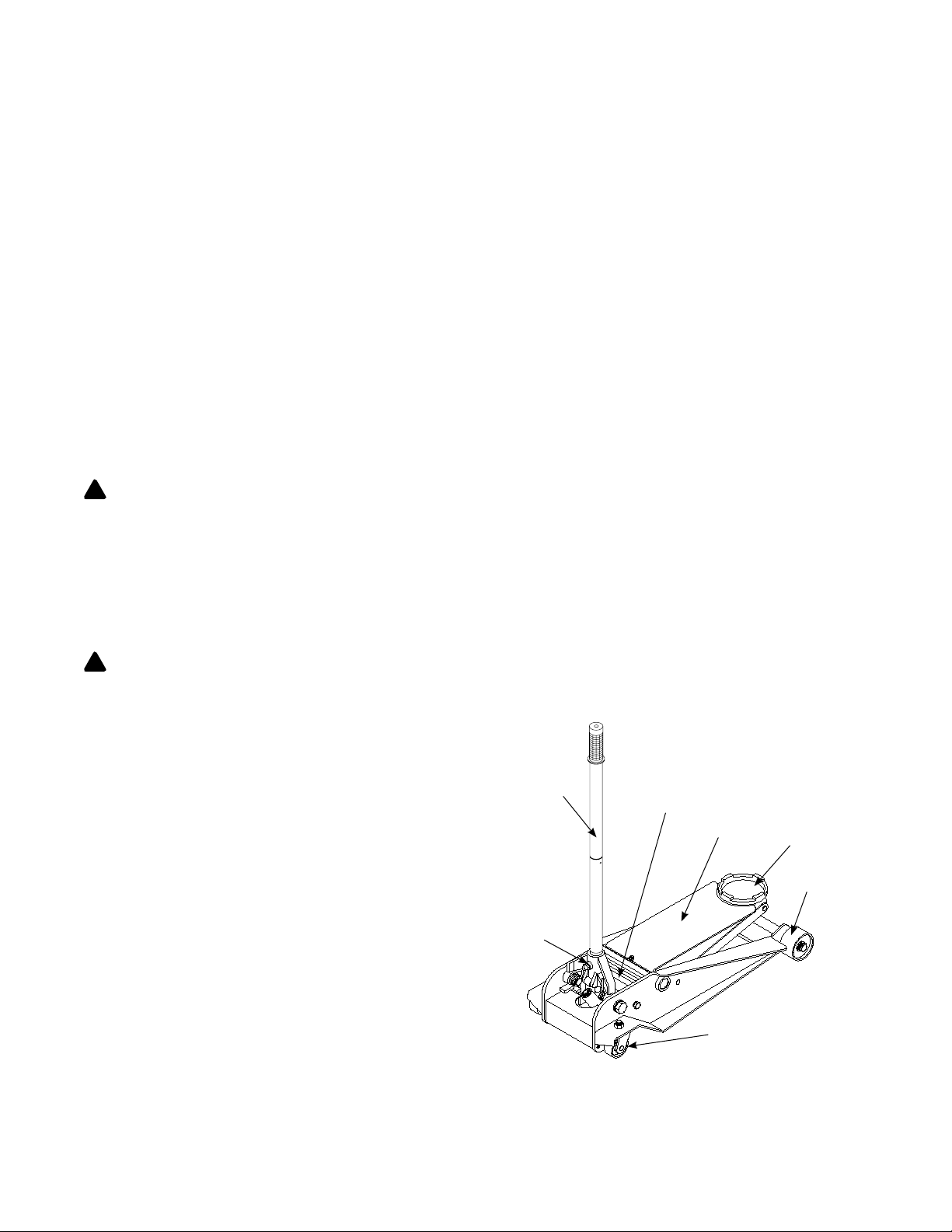
Figure 1 - Typical Jack Nomenclature
SAFETY AND GENERAL INFORMATION
Save these instructions. For your safety, read, understand, and follow the information provided with and on this
device before using. The owner and/or operator shall have an understanding of the device, its operating characteristics
and safety operating instructions before operating the equipment. The owner and/or operator shall be aware that use
and repair of this product may require special skills and knowledge. Instructions and safety information shall be read
to and discussed with the operator in the operator's native language, making sure that the operator comprehends
their contents, before use of this equipment is authorized. If any doubt exists as to the safe and proper use of this
device, remove from service immediately.
Inspect before each use. Do not use if abnormal conditions such as cracked welds, damaged, loose or missing
parts are noted. Any equipment that appears damaged in any way, is found to be worn, or operates abnormally shall
be removed from service until repaired. If the equipment has been or is suspected to have been subjected to an
abnormal load or shock, immediately discontinue use until inspected by a factory authorized repair facility (contact
distributor or manufacturer for list of authorized repair facilities). It is recommended that an annual inspection be
made by an authorized repair facility. Labels and Operator's Manuals are available from the manufacturer.
PRODUCT DESCRIPTION
This Hydraulic Service Jack is designed to lift, but not support, one end of a vehicle. MagicLift™ service jacks have
a unique feature that provides fast, no load lifts to the jacking point, at which time it lifts in approximately 0.75~0.2"
increments.
WARNING: Do not use hydraulic jack as stand-alone device. After lifting, immediately support the lifted vehicle
with a pair of appropriately rated jack stands.
PREPARATION/ASSEMBLY
Before Use
1. Assemble the 2-piece handle with provided bolt.
2. Always secure the handle into the handle fork by means of the bolt and lock washer provided. Tighten securely
to prevent accidental removal of handle while in use.
WARNING: Do not lift or carry jack by handle. Handle could dislodge and jack fall, resulting in possible injury
or property damage.
3. Before using this product, read the operator's manual
completely and familiarize yourself thoroughly with
the product and its components, and recognize the
hazards associated with its use.
4. Verify that the product and application are compatible.
5. To familiarize yourself with basic operation, locate and
turn the release valve (pump handle):
a. Clockwise until rm resistance is felt to further
turning. This is the ‘CLOSED’ release valve position
used to raise the saddle.
b. Counter-clockwise, but no more than 1/2 turn from
the closed position. This is the ‘OPEN’ release valve
position used to lower the saddle.
6. With saddle fully lowered and release valve closed,
pump the handle. If lift arm responds immediately,
jack is ready for use. If jack does not respond, follow
Bleeding/Venting Trapped Air instruction below.
Check oil level. Proper oil level will vary from just
covering the ram cylinder to 3/16” above it as seen
from the oil ller hole. Reinstall oil plug.
Handle
(release valve)
Saddle
Lift Arm
Oil Filler Plug
(ref. Parts illustration for location)
Caster
Front Wheel
Handle
Sleeve
!
!
SPECIFICATIONS
Model Capacity Jack Size (L x W x H) Min. Height Max. Height Saddle Dia. Volume of Hyd. Oil
YA642C 2-1/2 Ton 29-3/4" x 13-1/4" 4" 20" 5-1/2" 240 mL
3
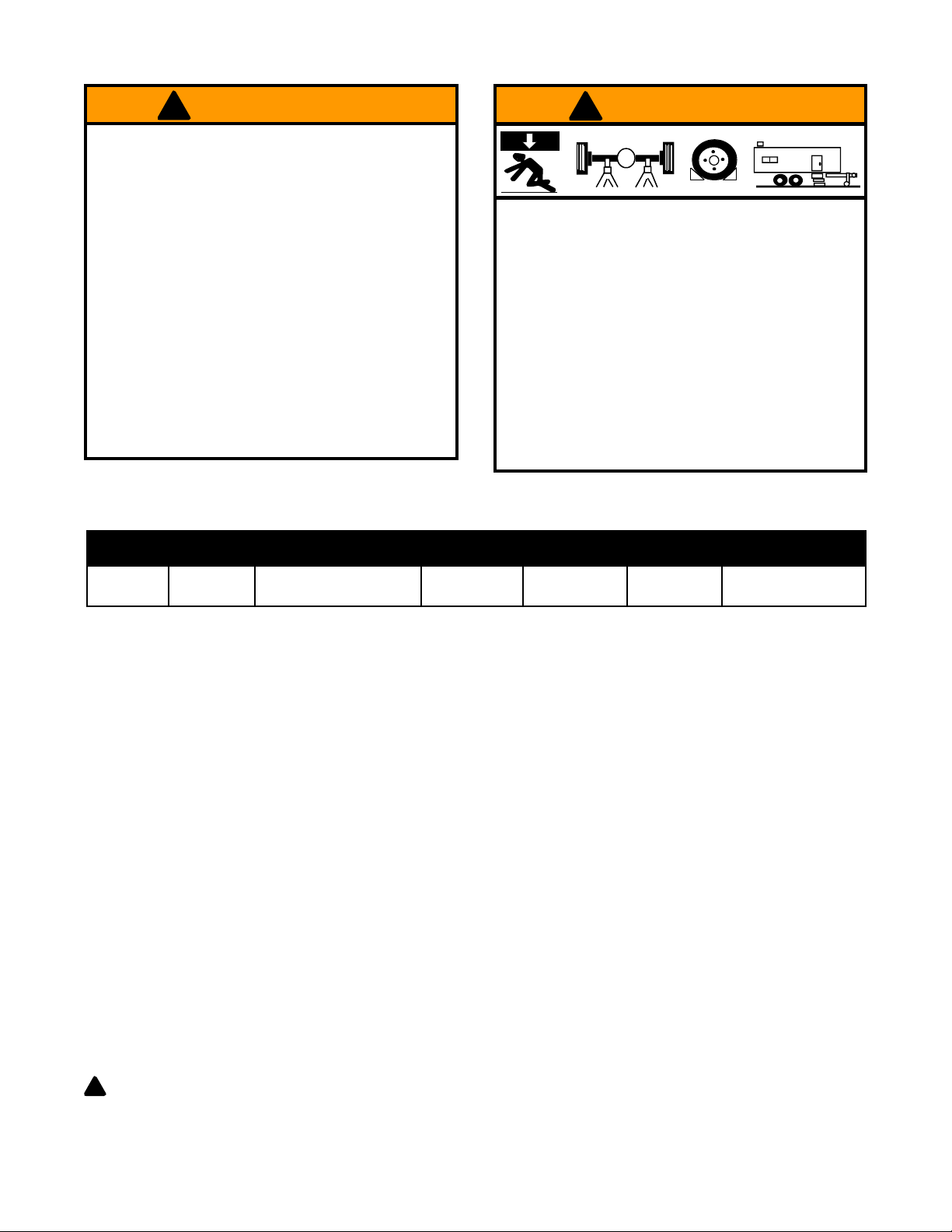
To avoid crushing and related injuries:
• Never work on, under or around a load supported
only by hydraulic jack.
• Always use adequately rated jack stands.
• Chock each unlifted tire in both directions.
• Do not use this device to lift, level, lower, support
nor move a house, mobile home, travel trailer,
camper or any building structure.
• Be alert and sober when using this product.
Do not operate under the inuence of drugs or
alcohol.
!WARNING
X
!WARNING
• Study, understand, and follow all instructions
before operating this device.
• Do not exceed rated capacity.
• Use only on hard, level surface.
• Lifting device only. Immediately after lifting,
support the vehicle with appropriate means.
• Lift only on areas of the vehicle as specied by
the vehicle manufacturer.
• Do not move or dolly the vehicle while on the
jack.
• No alterations shall be made to this product.
• Failure to heed these markings may result in
personal injury and/or property damage.
7. Ensure that jack rolls freely. Raise and lower the unloaded saddle throughout the entire lifting range before
putting into service to ensure the pump operates smoothly. Replace worn or damaged parts and assemblies with
authorized replacement parts only.
Bleeding/Venting Trapped Air
With the release valve in the OPEN position (step 5b. above) and with saddle fully lowered, locate and remove the
oil ller plug. Pump handle 6 to 8 full strokes. This will help release pressurized air which may be trapped within the
reservoir. Reinstall the oil ller plug and check operation.
OPERATION
Lifting
1. Follow the vehicle manufacturer’s recommended guidelines for lifting. Engage the emergency brake and chock
each unlifted wheel in both directions to prevent inadvertent vehicle movement.
2. Close the release valve by turning the handle clockwise until rm resistance is felt.
3. Refer to the vehicle manufacturer owner’s manual to locate approved lifting points on the vehicle. Center jack
saddle under lift point.
4. Verify lift point, pump handle until saddle contacts lift point. To lift, pump handle until load reaches desired height.
5. Transfer the load to appropriately rated jack stands.
Lowering
WARNING: Clear all tools and personnel before lowering vehicle. Open release valve slowly. The further
the pump handle is turned counter-clockwise, the faster the load will descend. Maintain control of load at all
times.
!

4
OPERATION (cont.)
1. Raise load high enough to clear the jack stands.
2. Remove jack stands carefully.
3. Turn handle counter-clockwise, but no more than 1/2 full turn. If the load fails to lower:
a. Use another jack to raise the vehicle high
enough to reinstall jack stands.
b. Remove the malfunctioning jack and then the
jack stands.
c. Use the functioning jack to lower the vehicle.
4. After removing jack from under the vehicle, fully lower the saddle to reduce ram exposure to rust and contamination.
MAINTENANCE
NOTICE: Use premium quality hydraulic jack oil. Avoid mixing different types of uid and NEVER use brake uid,
turbine oil, transmission uid, motor oil or glycerin. Improper uid can cause premature failure of the jack and the
potential for sudden and immediate loss of load.
Adding oil
1. With saddle fully lowered set jack in its upright, level position. Remove vent srew.
2. Fill with oil until ~3/16" above the inner cylinder as seen from the oil ller hole. Reinstall vent screw.
Changing oil
For best performance and longest life, replace the complete uid supply at least once per year.
1. With saddle fully lowered, remove vent screw.
2. Lay the jack on its side and drain the uid into a suitable container.
NOTICE: Dispose of hydraulic uid in accordance with local environmental regulations.
3. Fill with oil until ~3/16" above the inner cylinder as seen from the oil filler hole. Reinstall vent screw.
Lubrication
A periodic coating of light lubricating oil to pivot points, axles and hinges will help to prevent rust and assure that
wheels, casters and pump assemblies move freely.
Cleaning
Periodically check the pump piston and ram for signs of rust or corrosion. Clean as needed and wipe with an oily cloth.
NOTICE: Do not use sandpaper or abrasive material on ram and pump piston surfaces.
Storage
When not in use, store the jack with saddle fully lowered.

5
TROUBLESHOOTING
Symptom Possible Causes Corrective Action
Jack will not lift load • Release valve not tightly closed
• Load is too heavy
• Ensure release valve tightly closed
• Consider higher capacity jack
Jack will lift, but not maintain
pressure
•Release valve not tightly closed
• Hydraulic unit malfunction
•Ensure release valve tightly closed
• Discontinue use, contact Omega
technical service
Jack will not lower after unloading • Reservoir overlled
• Linkages binding
• Fluid level low
• Drain uid to proper level
• Clean and lubricate moving parts
• Ensure proper uid level
Poor lift performance • Fluid level low
•Hydraulic unit malfunction
• Ensure proper uid level
•Perform Bleeding/Venting Trapped
Air procedure, page 2)
Will not lift to full extension • Fluid level low • Ensure proper uid level
LIMITED WARRANTY STATEMENT
Snap-on Tools warrants this product to be free from defects in material and workmanship for a period of 1 year from
date of purchase. This warranty applies to the original purchaser (end user) only and is not transferable. Damaged
components and assemblies i.e. bent ram and pump pistons, dented reservoirs, cracked or altered components, are
the result of mis-use, mis-application or a combination of both. These conditions will not be considered for warranty
credit. We have complete condence that the Snap-on product you purchase will meet or exceed your performance
requirement. However in the unlikely event that a Snap-on product fails due to material or workmanship defect within
the warranty period you may contact your retailer for disposition or you may contact an Authorized Service Center
listed in the product owner’s manual. Except where such limitations and exclusions are specically prohibited by
law, the consumer’s sole and exclusive remedy shall be the repair or replacement of the defective product. Snap-on
shall not be liable for any consequential or incidental damage or loss whatsoever, and the duration of any and all
expressed and implied warranties, including without limitation, any warranties of merchantability and tness for a
particular purpose, is limited to a period of 1 year from date of purchase. Some States do not allow the exclusion
or limitation of incidental or consequential damages, so the above may not apply to you. This warranty gives you
specic legal rights. You may also have other rights which vary from state to state.

6
8
7a
7b
B
C
D
E
F
G
H
14
4
5
12
15
16
19
11 10
9
3
15
17
2
1
16
H
K
W
Q
P
N
M
A
L
J
S
T
U
V
13
N
18
J
6
7
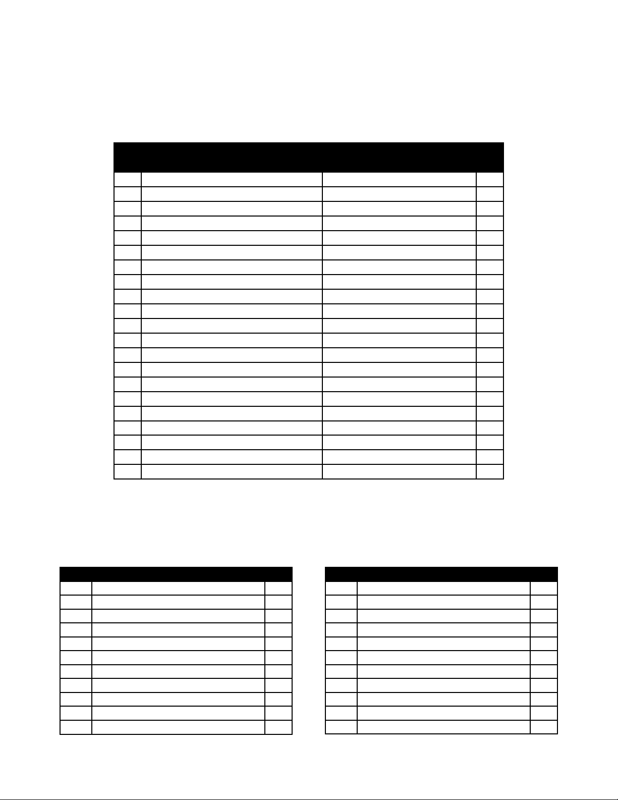
REPLACEMENT PARTS
Not all components of the jack are replacement items, but are illustrated as a convenient reference of location and
position in the assembly sequence. When ordering parts, please give the Model number, part number and parts de-
scription. Call or write for current pricing: SFA Companies 10939 N. Pomona Ave. Kansas City, MO 64153, U.S.A.
e-mail: [email protected]; Tel: (888) 332-6419; Fax: (816) 891-6599; Website: http://www.omegalift.com
Replacement Parts for models YA642C
Item Part No. for Model: Description Qty
YA642C
1 G610-11000-000 Hydraulic Power Unit 1
2 G640-90010-K02 Front Wheel Assy. 2
3 G610-90009-K03 Rear Caster Assy. 2
4 G610-00016-000 Saddle 1
5 G62S-03300-200 Vent Screw Assy. 1
6 G610-90009-K06 U-joing Assy. 1
7a G610-90009-K01 Handle (2 pc.) 1
7b G62S-04000-000 Handle (1 pc.) 1
8G933-0001-000 Handle Grip 1
95102-08016-000 Bolt, M8x16 1
10 G931-00009-000 Spring, Handle Sleeve (right) 1
11 G610-00008-000 Spring, Handle Sleeve (left) 1
12 G931-00003-000 Spring, Lift Arm 2
13 G610-03005-000 Spring, Pump 1
14 5404-04040-000 Retainer, 4x40 1
15 G610-00009-000 Handle Bolt 2
16 5303-00020-000 Lock Washer, M20 2
17 G931-00010-000 Bolt, M12 4
18 5303-00012-000 Lock Washer, M12 4
19 G610-00013-000 Cover 1
** G6900S-113 Repair Kit -
** Replacement requires special skills, knowlege, and equipment. Only authorized service center may perform
the repair and/or replacement of these items.
Repair Kit Contents
Item Description Qty
AO-ring, D7.8 x 2.65 4
BBack-up Ring 1
C O-ring, D15 x 2.65 1
D U-cup 1
EBack-up Ring 1
F O-ring, D44.5 x 2.4 1
GBack-up Ring 1
H O-ring, D63 x 2.65 2
JO-ring, D8.2 x 2.4 2
K O-ring, D31.6 x 3.5 1
LBack-up Ring 2
Item Description Qty
M Steel Ball, D9.52 2
N Steel Ball, D6.35 5
PBack-up Ring 1
Q O-ring, D6 x 3 1
RO-ring, D7.2 x 2.65 1
SBack-up Ring 2
T O-ring, D17.6 x 2.5 2
UBack-up Ring 1
V O-ring, D25 x 2.65 1
W Steel Ball, D6.74 1
O-ring, D8.8 x 1.9 (component of #5) 1

Table of contents
Other Blue point Jack manuals


