Blue point YA657B Owner's manual

OWNER/OPERATORMANUAL
MODELYA657B/YA660B/YA662B /YA667B
4 TON / 10 TON MANUAL SERVICE JACKS
4 TON / 10 TON AIR / MANUAL SERVICE JACKS
1
ASSEMBLY
EQUIPMENTNEEDEDFORASSEMBLY
1. Needle nose locking pliers
2. Snap-ring pliers (for: YA657B and
YA667Bonly)
3. 15 /16“ wrench (for: YA660B and
YA662Bonly)
4. Hammer
5. Tape measure
6. All necessary hardware is included
and is assembled loosely onto the
jack
ASSEMBLYINSTRUCTION
1. Remove the service jack base and
handle from the carton.
2. For YA657B and YA667B, see figure
1 to remove the retaining ring and the
handle pivot pin from the jack base
that connects through the handle
BEFOREUSE
1. Verify that the product and application
are compatible, if in doubt call Snap-
On technical service.
2. Read the operator's manual
completely and familiarize yourself
thoroughly with the product, its
components and recognize the
potential hazards associated with its
use before the use of this product.
3. Follow assembly instructions
4. Lower saddle fully.
5.Locate and remove the air vent screw.
6. Ensure the oil level is within ~ 3/16"
from the inner cylinder as viewed from
the air vent screw hole.
7.Reinstall the air vent screw.
8.Close release valve by turning the
release knob clockwise until firm
resistance is felt.
9.Ensure that the jack rolls freely.
10.Raise and lower the unloaded saddle
through out the lift range before putting
into service to ensure the pump and
release valve operate smoothly.
11.Replace worn or damaged parts and
assemblies with Snap-on Replace-
ment Parts only. (See Replacement
Parts Section).Lubricate as instructed
in Maintenance Section.
fork. For YA660B and YA662B (as
shown in figure 2) remove the 5/16-
18 bolts and the pin from the jack
base that connects through the
handle fork.
3. Remove the #6-32 screw and nut
from the universal receptacle on top
of the hydraulic unit.
4. Pull the universal assembly, located
on the bottom of the handle, out a
minimum of 1-3/4".
5. Clamp the needle nose locking
pliers onto the rod so that the
universal assembly will not retract
back into the handle.
6. Slide the universal assembly into the
handle socket so that it extends out
the other side.
7. Push the pivot pin that was removed
in step 2 back through the handle
and handle socket (may have to
gently tap the pin with a hammer).
8. Align the pivot pin with the holes on
the side plates that the pivot pin was
removed from and tighten the 5/16"-
18 bolts into the pivot pin until
secure. (for YA660B and YA662B
only)
9. Connect the universal assembly to
the universal receptacle rod using
the #6-32 screw and nut from note 4
(finger tighten only).
10. Remove the needle nose locking
pliers.
11. Jack is now operational and ready for
use.
Helpful hint:
If the jack cover is a hindrance, it can be
removed by using a 1/8" punch and
taping out the pivot pins (be sure to
attach the cover back to the jack after
assembly is completed).
(continued)
SAVE THESE INSTRUCTIONS
For your safety read, understand, and
follow the information provided with and
on these jacks. The owner and operator
of these equipments shall have an
understanding of these jacks and safe
operating procedures before attempting
to use. The owner and operator shall be
aware that use and repair of these
products may require special skills and
knowledge. Instructions and safety
information shall be conveyed in the
operator's native language before use
of these jacks are authorized. If any
doubt exists as to the safe and proper
use of this jack, remove from service
immediately.
Inspect before each use. Do not use if
there are broken, bent, cracked, or
damaged parts (including labels). Any
jack that appears damaged in any way,
operates abnormally, or is missing parts,
shall be removed from service immedi-
ately. If the jack has been or is suspected
to have been subjected to a shock load (a
load dropped suddenly, unexpectedly
upon it), immediately discontinue use
until the jack has been checked by a
Snap-on authorized service center. It is
recommended that an annual inspection
be done by qualified personnel. Labels
and Operator's Manual are available from
manufacturer.
PRODUCTDESCRIPTION
Blue-Point Hydraulic Service Jacks are
designed to lift,not sustain, ratedcapacity
loads. They are designed to be used in
conjunction with jack stands. Intended
use: To lift one wheel or one axle of a
vehicle for the purpose of service and/or
repair of vehicle components. After lifting,
loads must be immediately supported by
appropriately rated jack stands. Check
with vehicle owner's manual for proper lift
points.
DO NOT USE TO DOLLY OR MOVE
VEHICLE.
DONOTUSEFORANY PURPOSE
OTHERTHANTHOSEUSESOUTLINED
ABOVE!

2
!
•Study, understand, and follow
all instructions provided with
and on this device before
operating this device.
•Do not exceed rated capacity.
•This is a lifting device only.
•After lifting, immediately
transfer the load to appro-
priately rated vehicle stands.
•Neverworkon,under,oraround
aload supported bythisdevice.
•Use only on hard, level
surfaces capable of sustaining
rated capacity loads.
•Do not move or dolly loads with
this device.
•Do not modify this device.
•Do not use adapters or
accessories that are not
provided initially.
•Lift only on areas of the vehicle
as specified by the vehicle
manufacturer.
•Failure to heed these markings
may result in personal injury
and/or property damage.
!WARNING
To avoid crushing and related
injuries:
NEVER work on, under or around a
load supported only by a jack.
ALWAYS use adequately rated jack
stands. Immediately transfer loads
to appropriate jack stands.
OPERATION
Lifting
1. Place the vehicle in the park gear.
2. Engage the emergency brake.
3. Chock the wheels securely to prevent
inadvertent vehicle movement.
4. Locate and close the release valve by
turning release knob clockwise, firmly.
5.Centerjacksaddleunderliftpoint. Refer
to the vehicle manufacturer owner's
manualto locate approvedliftingpoints
on the vehicle.
6. Verify lift point then use handle pump to
contact lift point. To lift, pump handle
until load reaches desired height.
7. Transfer the load immediately to
appropriately rated jack stands.
To lower load
1. Raise load high enough to clear the
jack stands.
2. Remove jack stands, carefully. (always
used in pairs).
3. Slowly turn the release knob counter-
clockwise, but no more than 1/2 turn.
If the load fails to lower:
a. Use another jack to raise the
vehicle high enough to reinstall jack
stands.
b.Remove the malfunctioningjackand
then the jack stands.
c. Using the functioning jack, lower
the load by turning the operating
handle counterclockwise, but no
more than 1/2 turn.
4. Push saddle down to reduce ram
exposure to rust and contamination
after removing the jack from under the
load.
MAINTENANCE
Important: Use only a good grade
hydraulic jack oil. Avoid mixing different
types of fluid and Never use brake fluid,
turbine oil, transmission fluid, motor oil
or glycerin. Improper fluid can cause
failure of the jack and the potential for
sudden and immediate loss of load. We
recommend Mobil DTE 13M.
Addingoil
1. Lower saddle fully.
2. Set jack in its upright, level position.
3. Locate and remove air vent screw
4. Fill with oil until ~3/16" above the inner
cylinder as seen from the air vent
screw hole.
5. Reinstall the air vent screw
Changing oil
For best performance and longest life,
replace the complete hydraulic fluid at
least once a year.
1. Lower saddle fully.
2. Remove the air vent screw.
3. Lay the jack on its side and drain the
fluid into a suitable container.
Note: Dispose of hydraulic fluid in
accordance with local regulations.
4. Fill with oil until ~3/16" above the inner
cylinder as seen from the air vent
screw hole.
5. Reinstall the air vent screw.
Lubrication
A periodic coating of light lubricating oil to
pivot points, axles and hinges will help to
prevent rust and assure that wheels,
casters and pump assemblies move
freely.
Cleaning
Periodically check the pump piston and
ram for signs of rust or corrosion. Clean
as needed and wipe with an oily cloth.
Note: Never use sandpaper or abrasive
material on these surfaces!
Storage
Lower the saddle to its lowest position
when not in use.
• Leer, comprender, y seguir las
instrucciónes antes de utilizar el
aparato.
• El manual de instrucciónes y la
información de seguridad deben
estar comunicado en lengua del
operador antes del uso.
• No seguir estas indicaciónes puede
causar daños personales o
materiales.
!ADVERTENCIA
!WARNING

- KNOW YOUR PRODUCT -
3
Figure 3 - YA657B / YA660B Nomenclature Figure 4 - YA667B / YA662B Nomenclature
LiftArm
Air Hose
Saddle
Handle LiftArm
Handle Fork
Caster
Front Wheel
Release Knob
Saddle
Handle
Release Knob
Caster
AirMotor
AirVent Screw
(on the power unit)
AirVent Screw
(on the power unit)
Handle Fork
Min.Height Max.Height
5-1/4"
Capacity
26"
Model
5-1/4"
YA657B
Jack Size ( L x H )
4Ton
4Ton
26"
48-1/4" x 7-1/2"
YA667B
Air/Manual
YA660B
YA662B
Air/Manual
10Ton
10Ton
5-7/8"
5-7/8"
26"
26"
48-1/4" x 7-1/2"
53-3/8" x 9-3/4"
53-3/8" x 9-3/4"
Figure 1 - YA657B / YA667B Figure 2 - YA660B / YA662B
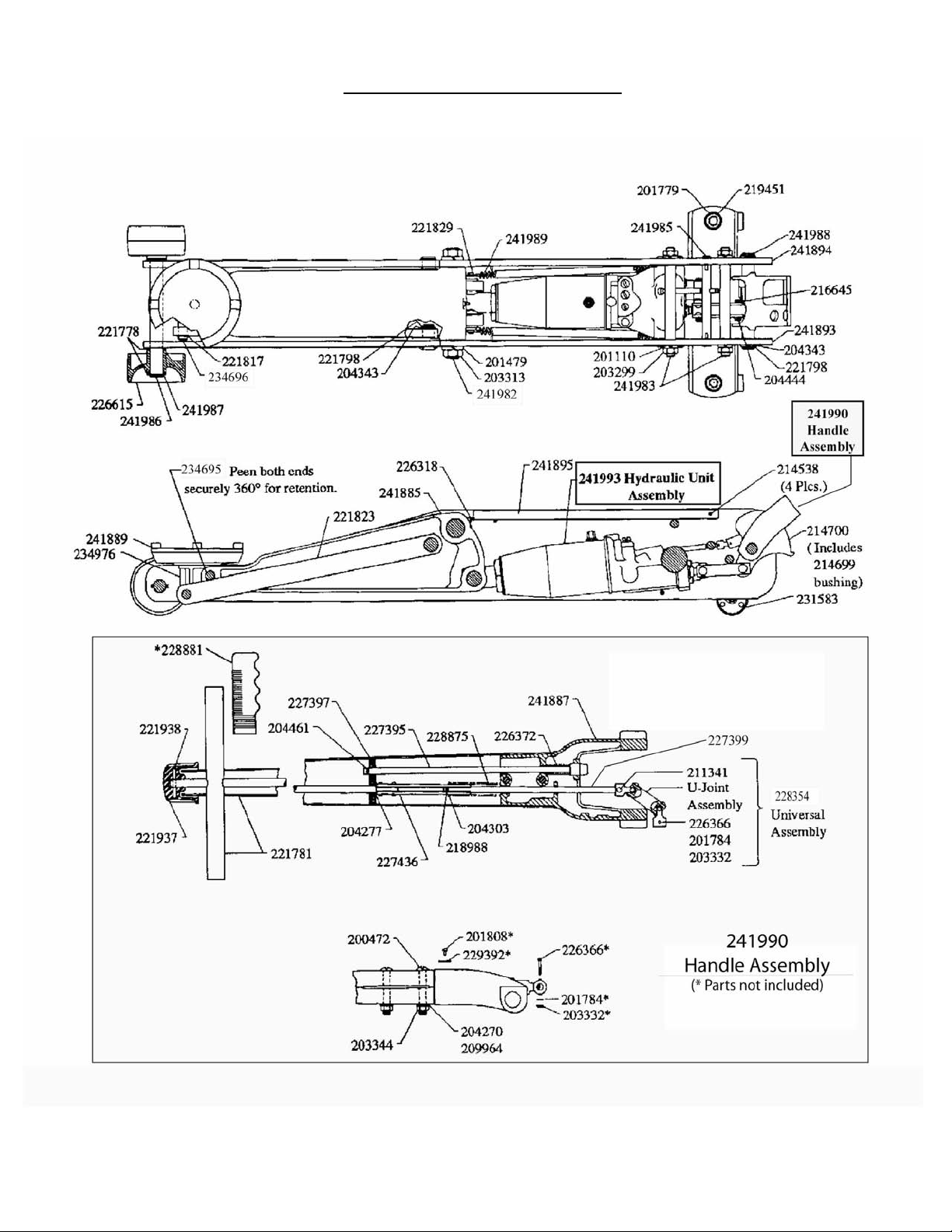
REPLACEMENTPARTS
(See attached exploded drawing)
When ordering replacement parts, please refer to the model number / serial number found on the product, then give the part
number and description.
Available Parts: Please refer to the Parts drawing when ordering parts. Not all components of the jack are replacement items, but
are illustrated as a convenient reference of location and position in the assembly sequence. When ordering parts, give Model
number, serial number and description below. Call or write for current pricing: Snap-on Tools Company, Kenosha, WI 53141-1410
4
TROUBLESHOOTING
• Contact Snap-on Technical Service
PossibleCauses Corrective Action
Jack will not lift load
Jack bleeds off after lift
Will not lift to full extension
• Release knob not tightly closed
• Fluid level low
• Hydraulic unit malfunction
• Ensure release knob tightly closed
• Ensure proper fluid level
Jack will not lower after unloading • Reservoir overfilled
• Linkages binding
• Fluid level low
• Drain fluid to proper level
• Clean and lubricate moving parts
• Ensure proper fluid level
Symptom

5
Service Parts for Model YA657B

6
Service Parts for Model YA657B (continued) - Hyd. Unit

7
Parts List for Model YA657B
Part# Description Qty.
200003hGasket 1
200472 Screw 2
201110 Lockwasher 4
201479 Lockwasher 2
201733 Plug 1
201779 Lockwasher 2
201784 Lockwasher 1
201808 Rivet 2
203198hBall (7/32" O.D.) 1
203199hBall (1/4" O.D.) 1
203200hBall (9/32" O.D.) 1
203201hBall (5/16" O.D.) 1
203205hBall (7/16" O.D.) 1
203299 JamNut 4
203313 JamNut 2
203332 Nut 1
203344 JamNut 2
204270 Washer 2
204277 Washer 1
204301 Washer 1
204303 Washer 1
204343 Washer 4
204372 Washer 1
204444 Cotter Pin 3
204461 Cotter Pin 1
204842hCopperGasket 1
209964 Lockwasher 2
210225 Spacer 1
210311 Pipe Plug 3
210411hWasher 1
211341 Rivet 1
212227 ReleaseValve 1
213152hPacking Ring 2
213171hPacking Ring 2
214538 GroovePin 4
214555hO-ring 1
214699 Bushing 1
214700 Handle SegmentAssy.1
216645 Pin 1
216646 PumpPin 1
218988 RollPin 1
219451 HexNut 2
220769 Cross Pin 1
221739hPoppet 1
221740 Ball Stop Plug(7/16" L)1
Part# Description Qty.
221742 Ball Stop Plug (3/4" L) 1
221764hRamQuadRing 1
221766 Cylinder 1
221770 LowPressurePump 1
221771hWasher 1
221772hQuadring 1
221778 Washer 4
221781 HandleandCross Bar 1
221798 RetainerRing 4
221817 RetainerRing 2
221823 Parallel Link 2
221829 Pin 1
221937 TurningKnob 1
221938 RollPin 1
222095 Release Stem Kit 1
222098 Speed Pump Assy. 1
222201hSpring 1
222257 PlugPoppetValve 2
222533hScreen 2
223166hRamScreen 1
226314 GlandNut 1
226318 GreaseFitting 1
226324 PressurePlug 1
226325 Pump Link 2
226326 Nut 1
226327 SlottedTube 1
226329 Pin 1
226331hSpring 1
226353hSpring 1
226366 Hex Head Bolt 1
226372 Spring 1
226615 FrontWheel 2
227395 Plunger Assy. 1
227397 ReleaseLink 1
227399 ExtensionRod 1
227436 TurningRodAssy. 1
228257hU-cup 1
228354 UniversalAssy. 1
228875 Spring 1
228881 Grip 2
229392 Serial Plate 1
229748hHeel Plate 3
229749 Washer 1
229750 Ram 1
229751 Pin 1
Part# Description Qty.
230583 Ram Assy. 1
231316 Vent Valve Assy. 1
231583 RearCaster 2
231638 FillerScrew 1
231710 OilTank 1
232968hBack-upWasher 1
232969hU-cup 1
232970 PressurePump 1
232971 Pressure Pump Kit 1
233798 TankNut 1
233880 TankNutand QuadRing1
233917hPlastic Spring 1
233921 ReleaseStem 1
234695 Bellcrank Pim 3/4x3.38 1
234696 Parallel Link Pin 1
234976 CapHousing 1
241885 Bellcrank 1
241887 HandleSocket 1
241889 Liftcap 1
241893 Sideplate Assy 1
241894 Sideplate Assy 1
241895 HydraulicUnitCover 1
241907 Repair Kit (Hyd. Unit) -
241982 Fulcrum Pin 1
241983 SideplateTie Rod 2
241985 SupportRod 1
241986 FrontAxle 1
241987 Retainerring 2
241988 HandlePivotPin 1
241989 ExtensionSpring 2
241990 Handle Assy. 1
241991 HydraulicUnitCasting 1
241993 Hydraulic Unit Assy. 1
YA657-K0 Label Kit (not shown)
YA657-M0 Manual
hIncluded in Repair Kit 241907

8
Service Parts for Model YA660B

9
Service Parts for Model YA660B (continued) - Hyd. Unit

10
Parts List for Model YA660B
Part# Description Qty.
200003 Gasket 1
200472 Bolt 2
201110 Lockwasher 4
201115 Lockwasher 2
201481 Lockwasher 2
201733 Expansion Plug 1
201784 Lockwasher 1
201789 Lockwasher 2
203198hBall 1
203199hBall 1
203200hBall 1
203201hBall 1
203207hBall 1
203272 Nut 2
203297 Nut 2
203299 Nut 2
203323 Nut 2
203332 Nut 1
203344 Nut 2
204270 Washer 2
204277 Washer 1
204301 Washer 1
204303 Washer 1
204372 Washer 1
204444 Cotter Pin 4
204461 Cotter Pin 1
204842hGasket 1
207169 Nut 2
209964 Lockwasher 2
210225 Spacer 1
210311 Pipe Plug 3
210411hWasher 1
211341 Rivet 1
212227 ReleaseValve 1
212689 Bolt 2
213152hPacking Ring 2
213171hPacking Ring 2
214538 GroovePin 4
214555hO-ring 1
214699 Bushing 1
214700 HandleSegment 1
& Bushing
216645 Pin 1
216646 Pin 1
217653 RollPin 2
218988 RollPin 1
218991 RollPin 1
Part# Description Qty..
220769 Cross Pin 1
221739 Poppet 1
221742 Ball Stop Plug 1
221770 SpeedPump 1
221771hBack-upWasher 1
221772 QuadRing 1
221781 Handle & Cross Bar 1
221809 HandleGrip 2
221937 ReleaseKnob 1
221938 RollPin 1
222095 Release Stem Assy. 1
222098 Speed Pump Assy. 1
222201hSpring 1
222257 Plug 1
222533hScreen 2
223166hScreen 1
224253 Cover 1
226271 Fulcrum Pin 1
226314 GlandNut 1
226318 GreaseFitting 5
226325 Pump Link 2
226326 GlandNut 1
226331 Spring 1
226353hSpring 1
226366 Bolt 1
226372 PlungerSpring 1
227397 Link 1
227436 TurningRodAssy. 1
228875 Spring 1
229887hO-ring 1
229888hO-ring 1
229889hO-ring 1
229896 Ram & Cylinder Assy. 1
229898 Cylinder 1
229899hU-cupPacking 1
229900hBack-upWasher 1
229902 Cross Pin 1
229903 Pin 1
229904 Plug 1
229905 Plug 1
229908 Spacer 1
229909 SlottedTube 1
229910 RetainingRing 2
229911 RetainingRing 2
229912 Washer 4
229913 BellCrank 1
229915 FrontWheel 2
Part# Description Qty.
229927 CapHousing 1
229929 Bearing 1
229932 Spring 2
229933 Plate 2
229934 Pin 1
229937 Caster 2
229938 Pin 1
229939 FrontAxle 1
229946 Pin 1
229947 RetainingRing 4
229949 HandleSocket 1
229951 Extensionrod 1
229952 Plunger Assy. 1
229956 Heel Plate 1
230006 BumperPin 1
230407 UniversalAssy. 1
231316 Filler Plug & Gasket Assy. 1
231419 Fulcrum Pin 1
231420 Bolt 2
231430 Parallel Link 2
231474 Bell Crank & Fittings 1
231638 Filler Plug & Vent Valve 1
231717 Base 1
231718 OilTank 1
231945 Ram Assy. 1
231962 Handle Assy. 1
231963 Front Wheel Assy. 2
232619 LiftingCap 1
232620 Swivel Pin 1
232968hBack-upWasher 1
232969hU-cupPacking 1
232970 PressurePump 1
232971 Pressure Pump &1
Gland Packing Assy.
233917 Plastic Spring 1
233921 ReleaseStem 1
240616 Repair Kit (Hyd. Unit) -
241482 TankNut 1
241483hSeal 1
241551 Hydraulic Unit Assy. 1
244317 Pin 1
245119 Ram 1
YA660-K0 Label Kit (not shown)
YA657-M0 Manual
hIncluded in Repair Kit 240616

11
Service Parts for Model YA662B

12
Service Parts for Model YA662B (continued) - Hyd. Unit

13
Service Parts for Model YA662B (continued) - Air Hyd. Pump
Parts List for Model YA662B
200003 Gasket 1
200472 Bolt 2
201110 Lockwasher 4
201115 Lockwasher 2
201481 Lockwasher 2
201733 Expansion Plug 1
201784 Lockwasher 1
201789 Lockwasher 2
203198hBall (7/32" O.D.) 1
203199hBall (1/4" O.D.) 1
203200hBall (9/32" O.D.) 1
203201hBall (5/16" O.D.) 1
203202 Ball (11/32" O.D.) 1
203207hBall 1
203272 Nut 2
203297 Nut 2
203299 Nut 2
203301 JamNut 1
203323 Nut 2
203332 Nut 1
203344 Nut 2
204270 Washer 2
204277 Washer 1
204301 Washer 1
204303 Washer 1
204372 Washer 1
204444 Cotter Pin 4
204461 Cotter Pin 1
204842hGasket 1
207169 Nut 2
209964 Lockwasher 2
210225 Spacer 1
210311 Pipe Plug 3
210411hWasher 1
211341 Rivet 1
212227 ReleaseValve 1
212689 Bolt 2
213152hPacking Ring 2
213171hPacking Ring 2
214538 GroovePin 4...Continue onnext page(page 14)
Part# Description Qty
214555hO-ring 1
214699 Bushing 1
214700 HandleSegment&1
Bushing
216645 Pin 1
216646 Pin 1
217653 RollPin 2
218988 RollPin 1
218991 RollPin 1
219861 O-ring 1
220769 Coss Pin 1
221013#U-cupPacking 1
221739 Poppet 1
221742 Ball Stop Plug 1
221770 SpeedPump 1
221771hBack-upWasher 1
221772 QuadRing 1
221809 HandleGrip 2
221820 RetainingRing 2
221937 ReleaseKnob 1
Part# Description Qty Part# Description Qty
Piston Assembly
231604
PistonAssembly
229999
Air-HydraulicPumpAssembly
CAUTION
Do not overtighten.
229754 tube must not
protude into I.D. pump
cylinder
Piston
35100007

14
Parts List for Model YA662B (continued)
221938 RollPin 1
222095 Release Stem Assy. 1
222098 Speed Pump Assy. 1
222201hSpring 1
222202 Elbow 1
222257 Plug 1
222288#O-ring 1
222533hScreen 2
223166hScreen 1
223172 Hose Clip 1
223173 ReturnSpring 1
223176 Cylinder,Air 1
223179 Hose Clip 2
223183 Plug 1
223184 Spring 1
223187#Valve& Plunger 1
223194 Spring&Cushion 1
223203 TripWasher 2
223220 Handle & Cross Bar 1
223678 Packing & Piston 1
223680 Screen 1
224021 Hose,Air 1
224081 Screw 2
224156 Spring 1
224469 Washer 1
225371 RubberCushion 1
225384 TripSpring 1
225906 Bracket, Speed pak 1
226153 Spring 1
226271 Fulcrum Pin 1
226314 GlandNut 1
226318 GreaseFitting 5
226325 Pump Link 2
226326 GlandNut 1
226331 Spring 1
226353hSpring 1
226366 Bolt 1
226372 PlungerSpring 1
226373 AdjustingScrew 1
226401 Spring 1
226450 End Block 1
226451 Set Screw 2
226483 PipeNipple 1
227397 Link 1
227436 TurningRodAssy. 1
227713 Lockwasher 1
228235 Cotter Pin 1
228813 Washer 1
228814#GlandNut 1
228815#U-cupPacking 1
228816#Washer 1
228875 Spring 1
229754 Pin 1
229887hO-ring 1
229888hO-ring 1
229889hO-ring 1
229896 Ram & Cylinder Assy.1
229898 Cylinder 1
229899hU-cupPacking 1
229900hBack-upWasher 1
229902 Cross Pin 1
229903 Pin 1
229904 Plug 1
229905 Plug 1
229908 Spacer 1
229909 SlottedTube 1
229910 RetainingRing 2
229911 RetainingRing 2
229912 Washer 4
229913 BellCrank 1
229915 FrontWheel 2
229927 CapHousing 1
229929 Bearing 1
229932 Spring 2
229933 Plate 2
229934 Pin 1
229938 Pin 1
229939 FrontAxle 1
229946 Pin 1
229947 RetainingRing 4
229949 HandleSocket 1
229951 ExtensionRod 1
229952 Plunger Assy. 1
229956 Heel Plate 1
229999 Air Hyd. Pump Assy. 1
230000 PumpCylinder 1
230003 Back-upWasher 1
230005 GlandNut 1
230006 BumperPin 1
230007 U-bolt 1
230008 Bracket 1
230010 Caster 2
230011 Spacer 1
230407 UniversalAssy. 1
231316 Filler Plug & 1
Gasket Assy.
231347 Piston & Roll Pin 1
231419 Fulcrum Pin 1
231420 Bolt 2
231430 Parallel Link 2
231474 Bell Crank & Fittings 1
231572 CylinderCap 1
231604 Piston Assy. 1
231619 Rod, Pump 1
231638 Fillerplug &VentValve 1
231717 Base 1
231718 OilTank 1
231945 Ram Assy. 1
231963 Front Wheel Assy. 2
231990 Handle Assy. 1
232619 LiftingCap 1
232620 Swivel Pin 1
232968hBack-upWasher 1
232969hU-cupPacking 1
232970 PressurePump 1
232971 Pressure Pump &1
Gland Packing Assy.
233110 PumpU-cup 1
233622 Screw 4
233897 Ring,Sealing 1
233917 Plastic Spring 1
233921 ReleaseStem 1
240564 Repair Kit (Air Pump) -
240616 Repair Kit (Hyd. Unit) -
241482 TankNut 1
241483hSeal 1
241552 Hydraulic Unit Assy. 1
244253 Cover 1
244317 Pin 1
245119 Ram 1
35100007 AirValve 1
YA662-K0 Label Kit (not shown) -
YA657-M0 Manual -
Part# Description Qty Part# Description Qty Part# Description Qty
hIncluded in Repair Kit 240616
#Included in Repair Kit 240564

15
Service Parts for Model YA667B

16
Service Parts for Model YA667B(continued) - Hyd. Unit

17
Service Parts for Model YA667B(continued) - Air Hyd. Pump
Parts List for Model YA667B
Part# Description Qty Part# Description Qty Part# Description Qty
200003hGasket 1
200472 Screw 2
201110 Lockwasher 4
201479 Lockwasher 2
201733 Plug 1
201779 Lockwasher 2
201784 Lockwasher 1
201808 Rivet 2
203198hBall (7/32" O.D.) 1
203199hBall (1/4" O.D.) 1
203200hBall (9/32" O.D.) 1
203201hBall (5/16" O.D.) 1
203202 Ball (11/32" O.D.) 1
203205hBall (7/16" O.D.) 1
203299 JamNut 4
203313 JamNut 2
203332 Nut 1
203344 JamNut 2
204270 Washer 2
204277 Washer 1
204301 Washer 1
204303 Washer 1
204343 Washer 4
204372 Washer 1
204444 Cotter Pin 3
204461 Cotter Pin 1
204842hCopperGasket 1
209964 Lockwasher 2
210225 Spacer 1
210311 Pipe Plug 4
210411hWasher 1
211341 Rivet 1
212227 ReleaseValve 1
213152hPacking Ring 2
213171hPacking Ring 2
213639 Bolt 1
214538 GroovePin 4
214555hO-ring 1
214699 Bushing 1
214700 Handle segment Assy. 1
216645 Pin 1
216646 PumpPin 1
218988 RollPin 1
219451 HexNut 2
220769 Cross Pin 1
221013#U-cupPacking 1
221377 RollPin 1
221739hPoppet 1
221740 Ball Stop Plug (7/16" L)1
221742 Ball Stop Plug (3/4" L)1
221764hRamQuadRing 1
221766 Cylinder 1
221770 LowPressurePump 1
221771hWasher 1
221772hQuadring 1
221778 Washer 2
221798 RetainerRing 4
221817 RetainerRing 2
221820 RetainingRing 1
221823 Parallel Link 2
...Continueonnext page(page 18)
242162
PistonAssembly
242160
Air-HydraulicPump Assembly
Piston
Assembly
242162
35100007

Parts List for Model YA667B (continued)
18
Part# Description Qty Part# Description Qty Part# Description Qty
221825 Parallel Link Pin 1
221829 Pin 1
221937 TurningKnob 1
221938 RollPin 1
222088 ScreenAssembly 1
222095 Release Stem Kit 1
222098 Speed Pump Assy. 1
222201hSpring 1
222202 Elbow 1
222257 PlugPoppetValve 2
222288#O-ring 1
222533hScreen 2
223166hRamScreen 1
223172 Hose Clip 1
223173 ReturnSpring 1
223179 Hose Clip 2
223183 Plug 1
223184 spring 1
223187#Valve& Plunger 1
223203 TripWasher 2
223213 GlandNut 1
223220 Handle & Cross Bar 1
223678 Packing & Piston 1
223680 Screen 1
224034 Air Cylinder 1
224038 PumpRod 1
224081 Screw 3
224156 Spring 1
224344 Ball Stop Plug 1
224414 RetainingRing 1
224469 Washer 1
225371 RubberCushion 1
225384 TripSpring 1
225906 Bracket, Speed pak 1
226019 LockNut 4
226153 Spring 1
226314 GlandNut 1
226318 Greasefitting 1
226319 Bellcrank Pin 1
226324 PressurePlug 1
226325 Pump Link 2
226326 Nut 1
226327 Slotted tube 1
226329 Pin 1
226331hSpring 1
226353hSpring 1
226366 Hex Head Bolt 1
226372 Spring 1
226373 AdjustingScrew 1
226450 End block 1
226451 Set Screw 2
226483 PipeNipple 1
226615 FrontWheel 2
227052 Washer 1
227395 Plunger Assy. 1
227397 ReleaseLink 1
227399 ExtensionRod 1
227436 TurningRodAssy. 1
228235 Cotter Pin 1
228257hU-cup 1
228354 UniversalLinkage 1
228813 Washer 1
228814#Glant Nut 1
228815#u-cupPacking 1
228816#Washer 1
228875 Spring 1
228881 Grip 2
229392 Serial plate 1
229748hHeel Plate 3
229749 Washer 1
229750 Ram 1
229751 Pin 1
229754 Extension tube 1
230003hBack-upWasher 1
230007 U-bolt 1
230430 Air Hose Assy. 1
230583 Ram Assy. 1
230753 SuctionTube 1
231316 Vent Valve Assy. 1
231572 CylinderCap 1
231583 RearCaster 2
231638 FillerScrew 1
231710 OilTank 1
232968hBack-upWasher 1
232969hU-cup 1
232970 PressurePump 1
232971 Pressure Pump Kit 1
233110 PumpU-cup 1
233798 TankNut 1
233880 Tank Nut & Quad Ring1
233917hPlastic Spring 1
233921 Releasestem 1
234976 CapHousing 1
236684 Piston 1
236685 Sealingring 1
240564 Repair Kit (Hyd. Pump) 1
241780 Handle 1
241885 Bellcrank 1
241887 HandleSocket 1
241889 Liftcap 1
241894 Sideplate Assy 1
241895 HydraulicUnitCover 1
241907 Repair Kit (Hyd. Unit)-
241955 Sideplate Assy 1
241956 Fulcrum Pin 1
241983 SideplateTie Rod 2
241985 SupportRod 1
241986 FrontAxle 1
241987 Retainerring 4
241988 HandlePivotPin 1
241989 Extensionspring 2
241992 Hydraulic Unit Casting1
241994 Hydraulic Unit Assy. 1
242160 Air Hyd. Pump Assy. 1
242161 PumpCylinder 1
242162 Piston Assy 1
243098 U-bolt 1
243101 Sleeve 1
35100007 AirValve 1
YA667-K0 Label Kit (not shown)
YA657-M0 Manual
hIncluded in Repair Kit 241907
#Included in Repair Kit 240564

LIMITED WARRANTY STATEMENT
Snap-on Tools warrants this product to be free from defects in material and workmanship
for a period of 1 year from date of purchase. This warranty applies to the original
purchaser (end user) only and is not transferable. Damaged components and assemblies
i.e. bent ram and pump pistons, dented reservoirs, cracked or altered components, are
the result of misuse, misapplication or a combination of both. These conditions will not be
considered for warranty credit. We have complete confidence that the Snap-on product
you purchase will meet or exceed your performance requirement. However in the unlikely
event that a Snap-on product fails due to material or workmanship defect within the
warranty period you may contact your retailer for disposition or you may contact an Au-
thorized Service Center listed in the product owner’s manual. Except where such limita-
tions and exclusions are specifically prohibited by law, the consumer’s sole and exclusive
remedy shall be the repair or replacement of the defective product. Snap-on shall not be
liable for any consequential or incidental damage or loss whatsoever, and the duration of
any and all expressed and implied warranties, including without limitation, any warranties
of merchantability and fitness for a particular purpose, is limited to a period of 1 year from
date of purchase. Some States do not allow the exclusion or limitation of incidental or
consequential damages, so the above may not apply to you. This warranty gives you
specific legal rights. You may also have other rights which vary from state to state.
Manufacturedfor Snap-onToolsCompany
2801 80th Street Kenosha,WI 53141-1410
Madein NorthAmerica
19

memo.
This manual suits for next models
3
Table of contents
Other Blue point Jack manuals