Blue point YA1544A Owner's manual

OWNER/OPERATOR MANUAL
MODEL YA1544A / YA1545
4 TON / 10 TON CAPACITY
HYDRAULIC
BODY REPAIR KIT
1
SAFETY INSTRUCTIONS
For your safety, read, understand, and
follow the information contained within.
The owner and operator shall have an
understanding of these products and safe
operating procedures before attempting to
use. Instructions and Safety information
shall be conveyed in the operators native
language before use of these products is
authorized. Make certain that the operator
thoroughly understands the inherent dan-
gers associated with the use and misuse
of the product. If any doubt exists as to
the safe and proper use of this product as
outlined in this factory authorized manual,
remove from service immediately.
Inspect before each use. Do not use
if there are broken, bent, cracked or
otherwise damaged parts (including
labels). If any component of these
products has been or suspected to have
been subjected to a shock load (a load
dropped suddenly, unexpectedly upon
it), discontinue use until checked out by
a Snap-on authorized service center.
Owners and operators of this equipment
shall be aware that the use and subsequent
repair of this equipment may require
special training and knowledge. It is
recommended that an annual inspection
be done by qualied personnel and that
any missing or damaged parts, decals,
warning / safety labels or signs be replaced
with Snap-on authorized replacement
parts only. Any component of these Body
Repair Kits that appears to be damaged in
any way, is worn or operates abnormally
shall be removed from service immediately
until such time as it can be repaired/
replaced. Labels and Operator's Manuals
are available from manufacturer.
PRODUCT DESCRIPTION
Blue-Point Hydraulic Body Repair Kits
are designed to be used for pushing,
spreading, and pressing of vehicle body
panels as well as various component parts
and assemblies. YA1544A is rated 8,000
psi with a 4 Ton ram and YA1545 is rated
10,000 psi with a 10 Ton ram.
WARNING: when extension tubes and/
or offset attachments are used, the rated
capacity is always reduced by 50 % for each
tube or offset attachment connected. See
Parts Section for identication of "offset"
attachments.
BEFORE USE
1. Read the manual completely and
familiarize yourself thoroughly with the
product, its components and recognize
the hazards associated with its use
before using this product.
2. Inspect before each use. Do not use
if there are bent, broken, leaking or
damaged components (including labels).
3. Ensure the product and application are
compatible and all parts of your kit are
included (see illustration and parts list).
4. Carefully remove the dust caps and plugs
from hose coupler and ram coupler.
5. Connect hose coupler to ram coupler.
6. Ensure there are no uid leaks.
7. Locate and open release valve, pump
handle a few strokes to purge air from
system. Close release valve and pump
handle until ram is fully extended, then
open release valve until ram has fully
retracted.
8. Place pump in horizontal position with
ram fully retracted and release valve
open.
9. Locate and open oil ller screw (on
reservoir body, near the back). This
will release air trapped within the
reservoir. Retighten the oil ller screw.
(continued)
General Safety Information:
1. Ensure the attachments are fully
engaged before applying load.
2. Ensure the load is centrally applied to
attachment or ram saddle. Do not load
off center.
3. Always monitor the force applied to
workpiece by using a load cell and
indicator or you may monitor pressure
developed in the ram by using an inline
pressure gauge, then calculate the
applied force using the formula: F
= P x A,
where F = lbs force, P = pressure in
PSI, and A = effective ram area in in².
Ram Area of YA1544A is: 1.00 in²
Ram Area of YA1545 is: 2.41in²
(refer to page 7 for load-pressure
correlation)
4. If bowing or bending of ram or any
attachment occurs during use, "STOP",
release pressure immediately and
reconsider application. Application
may not be compatible with product,
a ram kit with a higher capacity may
be needed.

such as battery acid, creosote-
impregnated objects and wet paint.
Hose deterioration due to corrosive
material can result in personal injury.
Never paint a coupler or hose.
• For good performance, do not expose
equipment to high temperature.
Extreme heat may damage hose
materials, packing and sealing.
• The user must be a qualied operator
familiar with the correct operation,
maintenance, and use of rams. Lack
of knowledge in any of these areas
can lead to personal injury.
• Read and understand all safety and
warning decals and instructions.
• Use only approved accessories and
approved hydraulic fluid. Hoses,
seals and all components used in a
system must be compatible with the
hydraulic uid used.
• Do not exceed the rated capacities of
the rams. Excess pressure can result
in personal injury.
• Inspect each ram and coupler before
each use to prevent unsafe conditions
from developing.
• Do not use rams if they are damaged,
altered or in poor condition.
• Do not use rams with bent or damaged
coupler or damaged threads.
• Under certain conditions, the use of
an extension with a ram may not
be advisable and could present a
dangerous condition.
• Avoid pinch points or crush points
that can be created by the load or
parts of ram.
• To help prevent material fatigue if the
ram is to be used in a continuous
application, the load should not exceed
85% of the rated capacity.
• Ram must be on a stable base which is
able to support the load while pushing
or lifting.
• Ensure ram is fully engaged into/onto
adapters, extension accessories.
• To help prevent personal injury, use
shims, friction material or constraints
to prevent slippage of the base or
load.
• Do not off-center loads on a ram. The
load can tip or the ram can "kick out"
and cause personal injury.
• Do not use the locking collar on
threaded piston as a stop. The threads
may shear resulting in loss of the load.
• If this component is used to lift or lower
loads, be certain that the load is under
operator control at all times and that
others are clear of the load. Do not
drop the load.
• As the load is lifted, use blocking and
cribbing to guard against a falling load.
• Never allow personnel to work on,
under or around a load before it is
properly supported by appropriate
mechanical means. Never rely on
hydraulic pressure alone to support
load.
• All personnel must be clear before
lowering.
• Never try to disassemble a hydraulic
cylinder, Refer repairs to qualied,
authorized personnel.
IMPORTANT
• Keep ram clean at all times.
• When the ram is not in use, keep the
ram(s) fully retracted.
• Use an approved, high-grade pipe
thread sealant to seal all hydraulic
connections. Teon tape can be used
if only one layer of tape is used and it is
applied carefully (two threads back) to
prevent the tape from being introduced
into hydraulic system. A piece of tape
could travel through the system and
obstruct the ow of uid and adversely
affect function.
• Never attach ANY component not
authorized by manufacturer.
• Never use other than factory provided
and/or authorized fasteners.
KNOW YOUR SYSTEM
Your ram, hose(s), couplings and pump
all must be rated for the same maximum
operating pressure, correctly connected
and compatible with the hydraulic uid
used. An improperly matched system
can cause the system to fail and possibly
cause serious injury. If you are in doubt,
consult your nearest Snap-on Dealer.
Center loads on
ram
2
Wear protective clothing
and safety goggles to
reduce the risk of injury.
• All WARNING statements must be
carefully observed to help prevent
personal injury. Do not exceed rated
capacity. Monitor pressure and load
at all times. Always verify load with
calibrated load cell and indicator,
known good pressure gauge or
equivalent devices. Wear appropriate
shoes. Do not wear sandals when
operating this equipment. Do not
wear jewelry when operating this
equipment.
Hydraulic Hoses and Fluid
Transmission Lines
• Avoid short runs of straight line tubing.
Straight line runs do not provide
for expansion and contraction due
to pressure and/ or temperature
changes.
• Reduce stress in tube lines. Long
tubing runs should be supported by
brackets or clips. Before operating the
pump, all hose connections must be
tightened with the proper tools. Do not
overtighten. Connections should only
be tightened securely and leak-free.
Overtightening can cause premature
thread failure or high pressure ttings
to burst.
• Should a hydraulic hose ever rupture,
burst or need to be disconnected,
immediately shut off the pump and
release all pressure. Never attempt
to grasp a leaking pressurized hose
with your hands. The force of escaping
hydraulic uid can inict injury.
• Do not subject the hose to potential
hazard such as re, sharp objects,
extreme heat or cold, or heavy impact.
• Do not allow the hose to kink, twist,
curl, crush, cut or bend so tightly that
the uid ow within the hose is blocked
or reduced. Periodically inspect the
hose for wear, because any of these
conditions can damage the hose and
possibly result in personal injury.
• Do not pull, position or move setup by
the hose. Doing so can damage the
hose and possibly cause personal
injury.
WARNING
!WARNING
!WARNING
!
3
MAINTENANCE
Important: Use only a good grade
hydraulic oil. Avoid mixing different types
of uid and Never use brake uid, turbine
oil, transmission uid, motor oil or glycerin.
Improper uid can cause premature failure
of the ram and the potential for sudden and
immediate loss of load. We recommend
Mobil DTE 13M or equivalent.
Adding oil
1. Lower ram fully
2. Set pump unit in its normal, level
position.
3. Locate and remove oil ller screw .
4. Fill until oil is within 3/8" of the ller
hole opening
5. Reinstall oil ller screw.
Changing oil
For best performance and increased
OPERATION
Caution: Never operate pump
connecting with hydraulic hoses
but without application. If operated in
this condition, the hydraulic hose and
connections become pressurized. This
increases burst hazard. Damage may
occur to pump and its components.
1. Locate and close release valve by
turning it clockwise until rmly closed.
(Do not over tighten)
2. Operate by pumping handle. This will
send uid from the pump reservoir into
the high pressure hose assembly and
into the ram assembly.
3. Continue pumping until ram reaches
desired position.
Note: To protect the ram, stop pumping
when ram is fully extended. Continued
pumping will pressurize the system.
4. Pump may be used in horizontal and
vertical position as illustrated below.
Figure 1 - Horizontal and Vertical Position
To Release Pressure on work piece:
Slowly, carefully, turn the release valve
counter-clockwise until ram retracts to
desired position. Never turn release valve
more than 1/2 full turn.
How to bleed air from ram:
Place ram upside down, fully extend and
retract the ram 2 or 3 times.
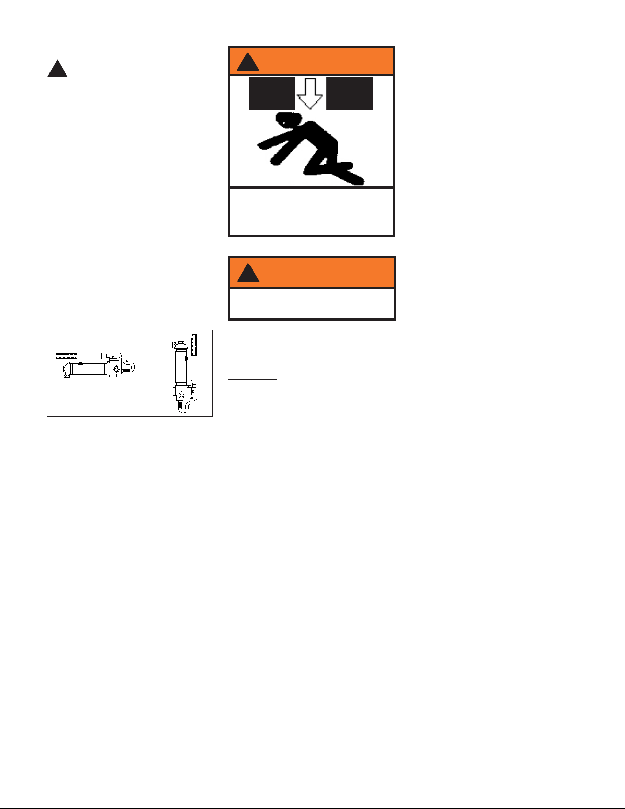
!
To avoid crushing and related injuries:
NEVER work on, under or around a
load supported only by a ram. ALWAYS
use adequately support device.
(continued)
system life, replace the complete fluid
supply at least once per year.
1. Lower ram fully
2. Remove the oil ller screw from the
pump reservoir as above.
3. Lay the pump on its side and drain the
uid into a suitable container.
Note: Dispose of hydraulic fluid in
accordance with local regulations.
4. Set pump in its level upright position.
5. Fill with good quality hydraulic oil to
within 3/8" of the oil ller screw hole
opening.
6. Reinstall oil ller screw.
Lubrication
A coating of light lubricating oil to pivot
points, axles and hinges will help to prevent
rust and assure that pump assemblies
move freely.
Note: Never use sandpaper or abrasive
material on these surfaces !
Cleaning
Periodically check the pump piston and
ram for signs of rust or corrosion. Clean as
needed and wipe with an oily cloth.
Storage
When not in use, store with the pump piston
and ram fully retracted.
How to remove a faulty coupler
If ram does not retract, secure load by
other means. Open pump release valve
to depressurize pump and hose. To avoid
the spilling from hydraulic oil, wraps
the grasping tool with rags or similar
padding. Remove the ram from application.
Disconnect and replace coupler.
Be sure all tools and personnel are clear
before lowering load.
WARNING
!
WARNING
!
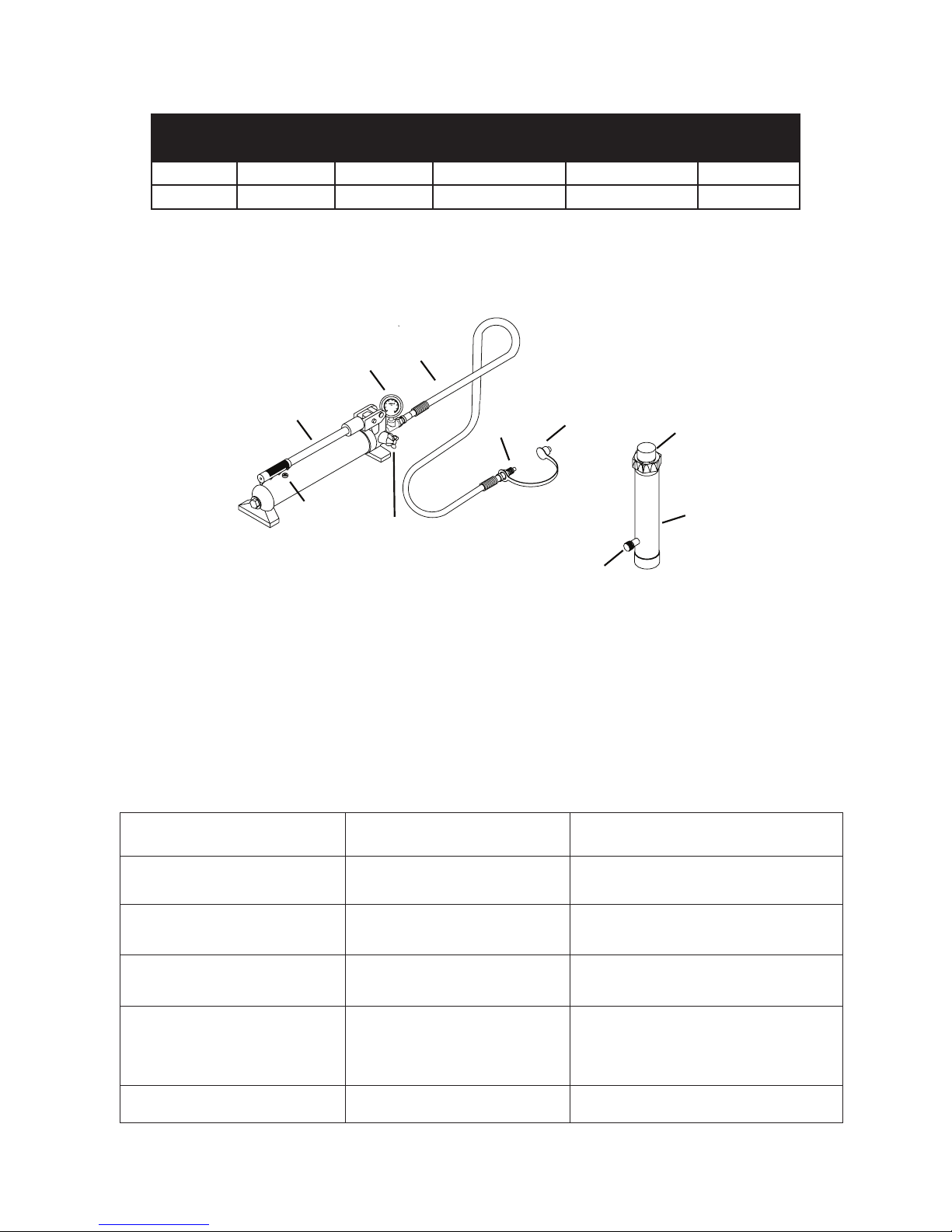
Figure 2 - Pump and Ram Components
4
- KNOW YOUR PRODUCT -
TROUBLESHOOTING
Symptom Possible Causes Corrective Action
Ram will not extend
Ram *bleeds off after extending
Will not lift to full extension
•Release valve not tightly closed
•Overload condition
• Hand pump uid level low
• Hand pump uid level low
•Air trapped in hand pump system
•Release valve not tightly closed
•Hydraulic unit malfunction
•Ensure release valve tightly closed
•Remedy overload condition
•Ensure release valve tightly closed
•Contact Service Center
• Ensure proper uid level
• Ensure proper uid level
• With ram fully retracted, remove oil ller
screw to let pressurized air escape, then
reinstall oil ller screw
Poor performance
• Hand pump reservoir overlled
•Ram damaged
• Drain uid to proper level
•Replace ram
* "Bleeds off" means that ram begins to slowly retract rather than maintain position.
Ram will not lower after un-
loading
Oil Filler
Screw
Handle
Release Valve
Plunger
Hose
Hose
Coupler
Ram Coupler
Ram
Dust Cover
Gauge
Model Pump
Capacity
Ram
Capacity
Ram Number of
Attachments
Closed Height Extended Height
YA1544A 8,000 psi 4 Ton 10-3/4” 15-5/8” 14
YA1545 10,000 psi 10 Ton 13-3/4” 19-3/4” 13

5
Figure 3 - Replacement Parts for Model YA1544A
REPLACEMENT PARTS
Please refer to Parts drawing when ordering parts. Not all components of the body repair kit are replacement items. When ordering parts,
give model number, serial number and parts description. Write for current pricing: Snap-on Tools Company, Kenosha, WI 53141-1410
Replacement Parts for Model YA1544A
1
20
3
18 17 16 15 14 13
12 11
4
10
9
8
76
5
2
21
19
23
22
24
Item Part No. Description Qty
1 F040-90211-K01 Pump Assembly 1
2F040-90009-K06 Ram Assembly 1
3 F040-22000-000 Hose Assembly (with coupler) 1
4 F040-00001-000 Blow Molded Case 1
5 F040-42000-000 Hydraulic Spreader (1000 lb. capacity) 1
6 F040-40002-000 Combination Head 1
7 F040-43000-000 Rubber Head 1
8 F040-40004-000 Ram Toe 1
9 F040-40005-000 Plunger Toe 1
10 F040-44000-000 Flat Base 1
11 F040-40003-000 Serrated Saddle 1
12 F040-40001-000 Wedge Head 1
13 F040-41600-000 Male connector 1
14 F040-41400-000 Extension Tube (3") 1
15 F040-41300-000 Extension Tube (6-1/8") 1
16 F040-41200-000 Extension Tube (8-1/2") 1
17 F040-41100-000 Extension Tube (16-1/2") 1
18 F040-41500-000 Extension Tube (19-1/2") 1
19 F040-22200-000 Release Valve Knob 1
20 F040-90009-K04 Ram Coupler Assy, Female 1
21 F040-20012-000 Dust Cover - Hose 1
22 F040-90009-K03 Pump Handle 1
23 F040-90107-K02 Oil Filler Screw 1
24 F100-80001-000 Gauge 1
- F0400S-85 Repair Kit -
- YA1544A-L0 Label 1
- YA1544A-M0 Manual 1

Load - Pressure Correlation For Model YA1544A & YA1545
Always monitor the force applied to workpiece by using a load cell and indicator or you may monitor pressure
developed in the ram by using an inline pressure gauge, then calculate the applied force using the formula:
F = P x A
For model BK104, A = 0.998 in² ;
For model BK105, A = 2.411 in²
Example1
Model YA1544A lifting 5,000 lbs will require what
presure?
Pressure = 5,000 lbs 0.998 in² = 5,010 psi
where F = Force/ Load (lbs);
P = Hydraulic working pressure (psi) and;
A = Ram effective area (in²)
Example2
Model YA1545 operating at 6,000 psi will gener-
ate what force?
Force = 6,000 psi x 2.411 in2= 14,466 lbs
7
Snap-on Tools Company
2801 80th Street Kenosha, WI 53141-1410

LIMITED WARRANTY STATEMENT
Snap-on Tools warrants this product to be free from defects in material and workmanship for
a period of 1 year from date of purchase. This warranty applies to the original purchaser
(end user) only and is not transferable. Damaged components and assemblies i.e. bent
ram and pump pistons, dented reservoirs, cracked or altered components, are the result of
mis-use, mis-application or a combination of both. These conditions will not be considered
for warranty credit. We have complete condence that the Snap-on product you purchase
will meet or exceed your performance requirement. However in the unlikely event that a
Snap-on product fails due to material or workmanship defect within the warranty period you
may contact your retailer for disposition or you may contact an Authorized Service Center
listed in the product owner’s manual. Except where such limitations and exclusions are
specically prohibited by law, the consumer’s sole and exclusive remedy shall be the repair
or replacement of the defective product. Snap-on shall not be liable for any consequential
or incidental damage or loss whatsoever, and the duration of any and all expressed and
implied warranties, including without limitation, any warranties of merchantability and tness
for a particular purpose, is limited to a period of 1 year from date of purchase. Some
States do not allow the exclusion or limitation of incidental or consequential damages, so
the above may not apply to you. This warranty gives you specic legal rights. You may
also have other rights which vary from state to state.
Manufactured for Snap-on Tools Company
2801 80th Street Kenosha, WI 53141-1410
Made in China
8
This manual suits for next models
1
Table of contents


