Blue Radio nBlue BT5.0 User manual

Page 1 of 195
AT.s LE Command Set v5.1.1b
Copyright © 2002-2021 BlueRadios, Inc.
200 S. Wilcox St., Unit 158 • Castle Rock, CO 80104 • USA • 303-957-1003 • sales@blueradios.com
www.BlueRadios.com
n
BlueTM BT5.0
AT.s LE Command Set v5.1.1b
BR-LE5.0-S1ASingle Mode Low Energy Module
(Actual Size Not Shown)
AT HOME. AT WORK. ON THE ROAD. USING BT5.0 WIRELESS TECHNOLOGY MEANS TOTAL
FREEDOM FROM THE CONSTRAINTS AND CLUTTER OF WIRES IN YOUR LIFE.
Subject matter contained herein is of highly sensitive nature and is confidential and proprietary to BlueRadios
Incorporated, and all manufacturing, reproduction, use, and sale rights pertaining to such subject matter are
expressly reserved. The recipient, by accepting this material, agrees that this material will not be used, copied or
reproduced in whole or in part nor its contents revealed in any manner to any person or other company except to
meet the express purpose for which it was delivered. This document includes data that shall not be disclosed outside
of your organization and shall not be duplicated, used, or disclosed, in whole or in part, for any purpose other than
to evaluate this document. BlueRadios, Incorporated, proprietary information is subject to change without notice.

Page 2 of 195
AT.s LE Command Set v5.1.1b
Copyright © 2002-2021 BlueRadios, Inc.
200 S. Wilcox St., Unit 158 • Castle Rock, CO 80104 • USA • 303-957-1003 • sales@blueradios.com
www.BlueRadios.com
Table of Contents
TABLE OF CONTENTS ..............................................................................................................................................2
REVISION HISTORY...................................................................................................................................................7
INTRODUCTION ................................................................................................................................................12
1.1 SCOPE.........................................................................................................................................................................12
1.2 BACKGROUND ............................................................................................................................................................12
1.3 LE PROTOCOL STACK.................................................................................................................................................13
BT5.0 NEW FEATURES.............................................................................................................................................................14
New LE Physical Layers (PHYs) ..........................................................................................................................14
Extended Advertising ............................................................................................................................................14
LE Secure Connections Pairing (LESC)................................................................................................................14
IMPORTANT NOTES –PLEASE READ PRIOR TO CONTINUING.................................................................15
2.1 IMPORTANT NOTES.....................................................................................................................................................15
2.2 BACKWARDS COMPATIBILITY.....................................................................................................................................16
2.3 KNOWN ISSUES...........................................................................................................................................................16
2.4 RELATED APPLICATIONS ............................................................................................................................................16
2.5 RELATED DOCUMENTS ...............................................................................................................................................16
HARDWARE NOTES .........................................................................................................................................17
3.1 POWER MODES ...........................................................................................................................................................17
3.2 ELECTRICAL SPECIFICATIONS SUMMARY ...................................................................................................................17
3.3 POWER-UP AND RESET................................................................................................................................................17
3.4 DEFAULT IO STATES ..................................................................................................................................................17
3.5 PIO FUNCTIONS..........................................................................................................................................................18
PIO_2/5/7/8 Status Indicators Outputs ..................................................................................................................18
PIO_3 - Sleep Mode Toggle Input.........................................................................................................................18
PIO_4 - Factory Reset / Connection Control Input................................................................................................18
PIO_6 - BRSP Comm Mode Toggle Input............................................................................................................18
PIO_14 - Firmware Upgrade Mode / Advertising Control Input...........................................................................19
3.6 UART INTERFACE......................................................................................................................................................19
3.7 USB INTERFACE.........................................................................................................................................................19
LOWERING POWER CONSUMPTION .............................................................................................................20
4.1 SLEEP MODE...............................................................................................................................................................20
Enabling/Disabling Sleep Mode............................................................................................................................20
UART and Sleep Mode .........................................................................................................................................20
Remote Commands and Sleep Mode.....................................................................................................................20
Shutdown Mode.....................................................................................................................................................21
Power Consumption Scenarios..............................................................................................................................21
4.2 IO CONSIDERATIONS ..................................................................................................................................................21

Page 3 of 195
AT.s LE Command Set v5.1.1b
Copyright © 2002-2021 BlueRadios, Inc.
200 S. Wilcox St., Unit 158 • Castle Rock, CO 80104 • USA • 303-957-1003 • sales@blueradios.com
www.BlueRadios.com
4.3 IDLE STATE.................................................................................................................................................................21
4.4 OUTPUT POWER /RECEIVE SENSITIVITY.....................................................................................................................21
4.5 ADVERTISING INTERVAL ............................................................................................................................................22
4.6 HIGHER CONNECTION INTERVAL................................................................................................................................22
4.7 SLAVE LATENCY.........................................................................................................................................................22
4.8 WHITELIST..................................................................................................................................................................22
4.9 DISABLE AUTO CONFIGURATION FLASHING...............................................................................................................22
4.10 STEPS FOR ENTERING THE LOWEST POWER STATE (SHUTDOWN .4 UA) .....................................................................22
COMMAND USAGE GUIDELINES....................................................................................................................23
5.1 COMMAND USAGE......................................................................................................................................................23
5.2 COMMON PARAMETER/RESPONSE VALUE DESCRIPTIONS ..........................................................................................23
5.3 BT5.0 ADDRESS FORMAT...........................................................................................................................................24
COMMAND STATUS RESPONSES..................................................................................................................25
6.1 OK..............................................................................................................................................................................25
6.2 ERROR ........................................................................................................................................................................25
EVENTS..............................................................................................................................................................26
7.1 GENERAL....................................................................................................................................................................26
Reset (RESET) ......................................................................................................................................................26
Bootloader (NBOOT)............................................................................................................................................27
Done (DONE)........................................................................................................................................................28
7.2 DISCOVERY.................................................................................................................................................................29
Non-Extended Discovery (DISCOVERY) ............................................................................................................30
Extended Discovery (EXT_DISCOVERY)...........................................................................................................31
7.3 CONNECTION ..............................................................................................................................................................32
Connect (CONNECT) ...........................................................................................................................................32
Disconnect (DISCONNECT) ................................................................................................................................33
Connection Parameter Update Status (SCCPS).....................................................................................................34
Connection Parameter Update (CPU)....................................................................................................................35
MTU Update (MTU) .............................................................................................................................................36
PHY Update (PHYU) ............................................................................................................................................37
RSSI (RSSI)...........................................................................................................................................................38
7.4 PAIRING......................................................................................................................................................................39
Pairing Request (PAIR_REQ) ...............................................................................................................................39
Paired (PAIRED)...................................................................................................................................................40
Pairing Failed (PAIR_FAIL) .................................................................................................................................41
Passkey Request (PK_REQ)..................................................................................................................................42
Passkey Display (PK_DIS)....................................................................................................................................43
Address Resolved (RESOLVED)..........................................................................................................................44
7.5 GATT CLIENT ............................................................................................................................................................46
GATT Done (GATT_DONE)................................................................................................................................46
GATT Discovered Primary Service (GATT_DPS) ...............................................................................................48

Page 4 of 195
AT.s LE Command Set v5.1.1b
Copyright © 2002-2021 BlueRadios, Inc.
200 S. Wilcox St., Unit 158 • Castle Rock, CO 80104 • USA • 303-957-1003 • sales@blueradios.com
www.BlueRadios.com
GATT Discovered Characteristic (GATT_DC).....................................................................................................49
GATT Discovered Characteristic Descriptor (GATT_DCD)................................................................................50
GATT Characteristic/Descriptor Value (GATT_VAL).........................................................................................51
GATT Long Characteristic/Descriptor Value (GATT_LVAL).............................................................................52
7.6 GATT SERVICE ..........................................................................................................................................................53
Battery Level Event (BATT).................................................................................................................................53
BRSP Status (BRSP) .............................................................................................................................................54
BRSP Data (BRSPD).............................................................................................................................................55
Custom Profile Read (CP_READ) ........................................................................................................................56
Custom Profile Write (CP_WRITE)......................................................................................................................57
COMMANDS.......................................................................................................................................................58
8.1 GENERAL....................................................................................................................................................................58
AT..........................................................................................................................................................................58
Help (ATHELP) ....................................................................................................................................................58
Response Mode (ATSRM) ....................................................................................................................................59
8.2 RESET.........................................................................................................................................................................61
Reset (ATRST)......................................................................................................................................................61
Factory Reset (ATFRST).......................................................................................................................................62
8.3 CONFIGURATION CONTROL ........................................................................................................................................63
Configuration Lock (ATSCL) ...............................................................................................................................63
Configure Flash Storage Configuration (ATSFC).................................................................................................65
Flash Configuration (ATFC) .................................................................................................................................66
Set Configuration (ATSCFG)................................................................................................................................66
Configuration Dump (ATCFG?) ...........................................................................................................................68
8.4 SLEEP..........................................................................................................................................................................69
Sleep (ATZ)...........................................................................................................................................................69
Sleep Configuration (ATSZ) .................................................................................................................................70
8.5 MODULE INFORMATION..............................................................................................................................................71
Module Type (ATMT?).........................................................................................................................................71
Stack Type (ATST?)..............................................................................................................................................72
Firmware Version (ATV?) ....................................................................................................................................72
BT5.0 Device Address (ATA?) .............................................................................................................................73
BT5.0 Device Name (ATSN) ................................................................................................................................74
Appearance (ATSAPP)..........................................................................................................................................75
Address Type (ATSAT) ........................................................................................................................................76
8.6 MODULE STATE..........................................................................................................................................................78
Get State (ATSLE?)...............................................................................................................................................78
Default Behavior (ATSDBLE)..............................................................................................................................79
Cancel/Idle Command (ATDC).............................................................................................................................80
8.7 HARDWARE CONFIGURATION /CONTROL...................................................................................................................81
Set Default Power Levels (ATSDPL)....................................................................................................................81
Set Current Power Level (ATSCPL) .....................................................................................................................82
UART Configuration (ATSUART).......................................................................................................................83
USB Configuration (ATSUSB) .............................................................................................................................85
NFC Configuration (ATSNFC) .............................................................................................................................86

Page 5 of 195
AT.s LE Command Set v5.1.1b
Copyright © 2002-2021 BlueRadios, Inc.
200 S. Wilcox St., Unit 158 • Castle Rock, CO 80104 • USA • 303-957-1003 • sales@blueradios.com
www.BlueRadios.com
PIO Configuration (ATSPIO)................................................................................................................................87
PIO Level (ATPIOL).............................................................................................................................................89
LED Configuration (ATSLED) .............................................................................................................................90
Get ADC (ATADC?).............................................................................................................................................91
Get Battery Level (ATBL?) ..............................................................................................................................93
Get Temperature (ATT?)...................................................................................................................................94
Calibrate Temperature Sensor (ATCT).............................................................................................................94
8.8 ADVERTISING .............................................................................................................................................................95
Advertise (ATDSLE).............................................................................................................................................95
Advertising Configuration (ATSDSLE)................................................................................................................96
Advertising Timing Configuration (ATSDSTLE).................................................................................................98
Advertising/Scan Response Data (ATSDSDLE)...................................................................................................99
8.9 DISCOVERY...............................................................................................................................................................104
Discovery (ATDILE)...........................................................................................................................................104
Discovery Configuration (ATSDILE) .................................................................................................................105
Discovery Timing Configuration (ATSDITLE) ..................................................................................................107
Discovery Event Formatting (ATSDIF) ..............................................................................................................108
8.10 CONNECTION ............................................................................................................................................................110
Connect (ATDMLE) .......................................................................................................................................110
Connect Last (ATDMLLE).............................................................................................................................112
Last Connect Address (ATLCALE?)..............................................................................................................113
Connect Configuration (ATSDMLE)..............................................................................................................114
Connect Timing Configuration (ATSDMTLE)...............................................................................................115
Connection Parameters....................................................................................................................................116
Default MTU (ATSDMTU)............................................................................................................................120
Connection PHYS ...........................................................................................................................................121
Connection Status (ATCS?)............................................................................................................................124
Connection RSSI (ATRSSI?)..........................................................................................................................126
Continuous Connection RSSI (ATCRSSI)......................................................................................................127
Disconnect Command (ATDH).......................................................................................................................128
8.11 PAIRING....................................................................................................................................................................129
Pair Command (ATPLE).................................................................................................................................129
Pairing Configuration (ATSPLE)....................................................................................................................131
Unpair Device (ATUPLE)...............................................................................................................................134
Clear Pair List (ATCPLE)...............................................................................................................................134
Passkey Response (ATPKR)...........................................................................................................................135
Passkey Confirm (ATPKC).............................................................................................................................136
Fixed Passkey (ATSPK)..................................................................................................................................137
8.12 WHITE LIST ..............................................................................................................................................................139
White List Device (ATSWL) ..........................................................................................................................139
Un White List Device (ATUWL)....................................................................................................................140
Clear White List (ATCWL) ............................................................................................................................141
8.13 GATT CLIENT ..........................................................................................................................................................142
Discover All Primary Services (ATGDPS).....................................................................................................142
Discover Primary Services by UUID (ATGDPSU) ........................................................................................143
Discover All Characteristics (ATGDC) ..........................................................................................................144
Discover Characteristics by UUID (ATGDCU)..............................................................................................145
Characteristic Descriptor Discovery (ATGDCD) ...........................................................................................146

Page 6 of 195
AT.s LE Command Set v5.1.1b
Copyright © 2002-2021 BlueRadios, Inc.
200 S. Wilcox St., Unit 158 • Castle Rock, CO 80104 • USA • 303-957-1003 • sales@blueradios.com
www.BlueRadios.com
Characteristic Read (ATGR)...........................................................................................................................147
Characteristic Read Multiple (ATGRM).........................................................................................................148
Characteristic Read Long (ATGRL) ...............................................................................................................149
Characteristic Read by UUID (ATGRU) ........................................................................................................150
Characteristic Write (ATGW).........................................................................................................................151
Characteristic Write No Response (ATGWN) ................................................................................................153
Characteristic Write Prepared (ATGWP/ATGWPE) ......................................................................................154
8.14 GATT SERVICE CONFIGURATION.............................................................................................................................156
Device Information Service (ATSDIS)...........................................................................................................156
Battery Service (ATSBAS) .............................................................................................................................159
DFU Service (ATSDFU).................................................................................................................................162
BRSP Service (ATSBRSP) .............................................................................................................................163
8.15 RF TESTING..............................................................................................................................................................169
LE Direct Test Mode (ATDTM).....................................................................................................................169
Test Mode (ATTEST).....................................................................................................................................169
Transmitter Test (ATTXT)..............................................................................................................................170
Receiver Test (ATRXT)..................................................................................................................................171
RF Observation (ATRFO)...............................................................................................................................172
8.16 BOOTLOADER ...........................................................................................................................................................173
Run Bootloader (ATBOOT)............................................................................................................................173
Bootloader Configuration (ATSBOOT)..........................................................................................................174
8.17 CUSTOM PROFILE .....................................................................................................................................................175
Custom Profile Settings (ATSCP)...................................................................................................................176
Custom Profile Service (ATSCPS) .................................................................................................................177
Custom Profile Update Value (ATCPUV)......................................................................................................181
Custom Profile Read Response (ATCPRR)....................................................................................................182
Custom Profile Write Response (ATCPWR)..................................................................................................183
EXTENDED EXAMPLES..................................................................................................................................184
9.1 ENABLING NOTIFICATIONS ON AN LE DEVICE USING GATT COMMANDS ...............................................................184
9.2 DISCOVERING AND CONNECTING WITH EXTENDED ADVERTISING............................................................................186
Advertising Data Format .....................................................................................................................................188
Relevant Commands............................................................................................................................................188
House Example....................................................................................................................................................189
COMMAND SET SUMMARY TABLE..............................................................................................................190
10.1 COMMAND STATUS RESPONSES................................................................................................................................190
10.2 EVENTS.....................................................................................................................................................................190
10.3 COMMANDS..............................................................................................................................................................191
APPENDIX A: ACRONYMS/ABBREVIATIONS.....................................................................................................195

Page 7 of 195
AT.s LE Command Set v5.1.1b
Copyright © 2002-2021 BlueRadios, Inc.
200 S. Wilcox St., Unit 158 • Castle Rock, CO 80104 • USA • 303-957-1003 • sales@blueradios.com
www.BlueRadios.com
Revision History
Rev #
Date
Description
5.0.6.0
11/27/2018
New Features:
▪BT5.0 support 2Mbps and Long Range PHY support, extended advertising
packets, LE Secure Connections pairing.
▪Up to 8dBm output power now supported.
▪BRSP throughput up to 50kBps.
▪Single mode modules can now be connected to 5 devices simultaneously (1
as a peripheral and 4 as a central).
▪Configurable MTU up to 247 bytes.
▪USB and NFC support.
▪Dedicated Over the Air Firmware Update (DFU) service. Firmware updates
no longer done through BRSP service.
New Commands:
▪AT? Used to display a list of all available commands.
▪ATSCFG Allows reading/writing the entire config in only a few commands.
▪ATSDPL Replaces ATSPL to set default output power level. TX_Power is
set separately for Advertising and Scanning, RX_Sensitivity is fixed so that
parameter has been removed.
▪ATSCPL Sets the current power level for an active connection.
▪ATSUSB Allows USB serial ports to be enabled/disabled.
▪ATSNFC Allows NFC pairing to be enabled/disabled.
▪ATSPIOL Allows temporary changing of PIO output level.
▪ATSDMLE Allows Channel_Map to be set for ATDMLE and default BRSP
mode to be set.
▪ATSDMTU Allows the default MTU (Maximum Transmission Unit) to be set.
▪ATSSPHY Sets the PHYs the module will accept if a connection PHY
update is requested by another device.
▪ATSCPHY Requests to change the current PHY for a connection.
▪ATCRSSI Allows the RSSI to be continuously sampled when in a
connection.
▪ATPKC Allows module to respond to a PK_REQ event that requires
confirmation to complete a numeric comparison as part of LESC pairing.
▪ATGRM - GATT Read Multiple. Allows multiple characteristics to be read at a
time. This feature is only supported in the client role, so it is not possible to
use ATGRM to another BR-LE5.0-S1 or PAN1780-AT module.
▪ATSBASL Used to set the BAS battery level when in manual mode.
▪ATBRSPW Allows BRSP data to be sent via commands instead of a
stream.
▪ATDTM Allows device to enter Direct Test Mode for RF testing.
▪ATTEST Puts the device into an AT command test mode where ATTXT and
ATRXT can be used.
▪ATBOOT Used to run the bootloader.
▪ATSBOOT Used to configure the bootloader.
▪ATSDFU Used to enable/disable the Over the Air Firmware Update service.
New Events:
▪EXT_DISCOVERY Added to support BT5.0 extended advertising.
▪MTU Added to support changing the connection MTU (maximum
transmission unit). By default, this will now print after a CONNECT event

Page 8 of 195
AT.s LE Command Set v5.1.1b
Copyright © 2002-2021 BlueRadios, Inc.
200 S. Wilcox St., Unit 158 • Castle Rock, CO 80104 • USA • 303-957-1003 • sales@blueradios.com
www.BlueRadios.com
once the MTU has been negotiated. Can be disabled using the ATSRM
command.
▪PHYU Added to support the different BT5.0 PHYs and being able to change
the current PHY during a connection.
▪BRSPD A new BRSP data event that can be enabled in ATSBRSP to have
brsp data be delivered in events instead of a raw stream of data.
▪RSSI Similar behavior as before, but now considered an event.
Document Format Changes:
▪All dual mode commands have been removed to simplify the document.
▪The location of some of the events/commands in the document has changed
to better group related events/commands together.
Response Format Changes:
▪Leading zeroes have been removed from response values.
Optional Parameters:
▪All optional parameters will use the default value if not specified. In version
3.5 a change was made so that for commands that store in flash with optional
parameters, if an optional parameter was not specified then the current value
was used. This has not been implemented in this version.
Address Format Changes:
▪The BT5.0 Address and address type have now been combined into a single
parameter for all commands/events using an address. See BT5.0 Address
Format for more details.
PIO Functionality Changes:
▪Pulsing PIO_14 can be used to start/stop advertising.
▪PIO_7 is now an LED output that can be configured to blink at a desired rate
or to show sleep status using ATSZ.
▪PIO_8 is now an LED output that by default will flash once when a command
is received and can also be configured to blink at a desired rate.
▪ATRFO used to enable RF RX/TX debugging on PIO 8/9 and now defaults to
19/20. The PIOs can also be specified through the command now.
▪Unused PIOs will now default to a disconnected state instead of a pulled
down input state.
Event Format Changes:
▪RESET - Reset reason added. FACTORY_RESET will no longer be printed
on a factory reset. Factory_Reset is now a value in the RESET event.
▪DISCOVERY - COD/Addr_Type value removed.
▪CONNECT Conn_Type replaced with Conn_Role value. Pair_Status
changed to Paired.
▪PAIR_REQ Added Conn_Handle value and removed Pairing_Type value.
▪PAIRED Added Conn_Handle, Bonded and Security_Level values, removed
Pairing_Status value.
▪PAIR_FAIL Added Conn_Handle value.
▪PK_REQ Added Conn_Handle value.
▪PK_DIS Added Conn_Handle and Confirmation_Required values.
▪GATT_VAL Added Value_Format value.
▪BRSP event now reports TX_Mode and RX_Mode.
Command Changes:

Page 9 of 195
AT.s LE Command Set v5.1.1b
Copyright © 2002-2021 BlueRadios, Inc.
200 S. Wilcox St., Unit 158 • Castle Rock, CO 80104 • USA • 303-957-1003 • sales@blueradios.com
www.BlueRadios.com
▪ATSRM - Individual events can now be disabled using the
Response_Event_Flags parameter.
▪ATCFG? The order of the response for the command has been changed to
match the order of the commands in the document.
▪ATSFC - Storing of last connected address can now be disabled to prevent
writing to flash after every connection to a different device. If automatically
storing to flash has been disabled through ATSFC, an individual command
character to the end of the command string, for example
ATSN#,NewModuleName<cr>.
▪ATZ - Module can now be put into a shutdown state using new Shutdown
parameter.
▪ATSZ - Added Shutdown_PIO_State parameter to set the state of the IO in
shutdown mode.
▪ATSAT Added Privacy_Type and Private_Addr_Cycle_Time parameters.
Resolvable private random address no longer considered an address type but
can be enabled through the Privacy_Type parameter.
▪ATSDBLE Removed the Bridge parameter as this is not supported (was
only supported on the dual mode module previously).
▪ATSPL Replaced by ATSDPL and now TX_Power is set separately for
Advertising and Scanning, RX_Sensitivity is fixed so that parameter has been
removed.
▪ATSPIO Added Pull_Drive_Strength parameter to allow pull ups/downs for
inputs and drive strength for outputs.
▪ATSLED 2 more LEDs can now be configured: PIO_7, PIO_8.
▪ATADC? Added support for changing Resolution, Gain and Acquisition
Time.
▪ATDSLE/ATDSDLE ATDSDLE removed, direct advertising can now be
done using ATDSLE with new Direct_Addr and Direct_Duty_Cycle
parameters.
▪ATSDSLE Added new Ad_Types and new params to support extended
advertising.
▪ATSDSTLE Connected_Ad_Interval can now be set as low as 20ms.
▪ATSDSDLE Can now set data for Extended Advertising Data.
▪ATDILE Added Extended_Primary_Phys parameter to allow scanning for
extended advertising packets. By default, if not specified the module will
discover both non-extended and extended ad packets on the 1Mbps PHY.
▪ATSDILE Max_Devices can now be set up to 50, Channel_Map parameter
added.
▪ATSDITLE Timeout now specified in seconds.
▪ATSDIF Added Discovery_Type_Format to allow Discovery_Type to be
formatted in the standard format, as a bitfield, or as a string. Also added
Global_Format parameter to allow DISCOVERY and EXT_DISCOVERY
events to be formatted the same instead of as 2 separate events.
▪ATDMLE Added Extended_Primary_Phys parameter to allow connecting to
a device that is advertising using extended ad packets.
▪ATSDMTLE Timeout now specified in seconds.
▪ATCS? Response changed: Replaced Conn_Type with Conn_Role,
Pairing_Status with Security_Level. Added Conn_Interval, Slave_Latency,
Supervision_Timeout, MTU, RX_PHY, TX_PHY, and TX_Power.
▪ATSPLE Added LESC parameter to enable/disable LE Secure Connections.
Sync_White_List now enabled by default.
▪ATPKR Address can no longer be specified, only Conn_Handle.

Page 10 of 195
AT.s LE Command Set v5.1.1b
Copyright © 2002-2021 BlueRadios, Inc.
200 S. Wilcox St., Unit 158 • Castle Rock, CO 80104 • USA • 303-957-1003 • sales@blueradios.com
www.BlueRadios.com
▪ATSDIS Disabled characteristics will now actually be removed from the
service. Any changes to this command now require a reset to take effect.
▪ATSBAS When in manual mode the BATT event will no longer fire when a
client has registered/deregistered for notifications/indications. Manual mode
level is no longer specified in this command and can be set using ATSBASL.
▪ATSBRSP Removed OTA Firmware Update Mode from Features as OTA
updates are no longer done through BRSP, but through a dedicated DFU
service. Added LESC option to Security_Mode. Added TX_Mode and
RX_Mode to allow user to set whether to use Serial Port streaming mode or
command/event based BRSP.
5.0.6.1
05/29/2019
Document Changes:
▪Updated contact information.
5.0.6.2
01/17/2020
Document Changes:
▪Fixed document formatting issues.
5.0.6.3
06/24/2020
Document Changes:
▪Fixed Sync_White_List default value set to 1 in Pairing Configuration
(ATSPLE).
5.0.11.11
10/21/2020
Document Changes:
▪Added support for PAN1780-AT.
5.1.0.0
12/04/2020
New Features:
▪Custom Profile allows a host connected via UART/USB to add custom
GATT services.
New Events:
▪CP_READ used to signal the host that a client is trying to read a custom
characteristic or descriptor.
▪CP_WRITE used to signal the host that a client is trying to write to a custom
characteristic or descriptor.
New Commands:
▪ATSCP Used to set custom profile settings.
▪ATSCPS Used to add a custom profile service to the Attribute Table.
▪ATCPUV Used to update characteristic and descriptor value in custom
profile.
▪ATCPRR Used to respond to a CP_READ event.
▪ATCPWR Used to respond to a CP_WRITE event.
Changes:
▪Upgraded to Nordic nRF5 SDK 17.0.2 and SoftDevice 7.2.0
Bug Fixes:
▪Fixed ATGDC not working for unknown UUIDs
▪Fixed Buttons sometimes not working after first reset
▪Fixed module sometimes going into DTM mode on awaking from shutdown
via PIO_3
▪Fixed bug in Gatt Read Long that would cause buffer overrun and would
overwrite OK responses value
▪Fixed bootloader clearing restart reason, preventing RESET reason 5

Page 11 of 195
AT.s LE Command Set v5.1.1b
Copyright © 2002-2021 BlueRadios, Inc.
200 S. Wilcox St., Unit 158 • Castle Rock, CO 80104 • USA • 303-957-1003 • sales@blueradios.com
www.BlueRadios.com
▪Fixed GATT Write Prepared offset not declared as unit16
Documentation Changes:
▪ATRST - added Delay as optional with default value of 0=Reset Immediately
▪ATSFC - marked Store_Last_Connected_Address as optional with default
value 1=Enabled
▪ATADC? - Added Oversampling Mode with default value of 0=Disabled
5.1.0.0a
01/21/2021
Documentation Changes:
▪ATSCPS - Fixed characteristic/descriptor Maximum Attribute Value Lengths to
be uint16 in little-endian format.
5.1.1.0
02/18/2021
Changes:
▪Added hardware version checks in bootloader to prevent updating to firmware
built for wrong module.
Bug Fixes:
▪Fixed Device Information Model Number to be PAN1780 for PAN1780
module.
5.1.1.0a
03/23/2021
Documentation Changes:
▪Changed to BT5.0.
5.1.1.0b
03/31/2021
Documentation Changes:
▪Added notes that LEDs (PIO_2/5/7/8) and buttons (PIO_3/4/6/14) are inverted
for PAN1780.
▪Updated URLs.

Page 12 of 195
AT.s LE Command Set v5.1.1b
Copyright © 2002-2021 BlueRadios, Inc.
200 S. Wilcox St., Unit 158 • Castle Rock, CO 80104 • USA • 303-957-1003 • sales@blueradios.com
www.BlueRadios.com
Introduction
“Our clients buy our products because they are reliable and easy to integrate, enabling them to quickly
deploy cost-effective wireless solutions.”
Mark J. Kramer –CEO of BlueRadios
1.1 Scope
This document describes the protocol used to control and configure BlueRadios
n
Blue™modules. The protocol is
similar to the industry standard Hayes AT protocol used in telephone modems due to the fact that both types of
devices are connection oriented. The command set is similar to the one used in BlueRadios BT Version 4.0
modules, but many changes have been made to improve the user experience. Users already familiar with the AT.s
Command Set v3.X command set will want to read the new command set documentation carefully, paying
attention to all the changes that have been made.
Just like telephone modems, the serial modules power up into an unconnected state and will respond to inquiry
and connection requests. Then, just like controlling a modem, the host or client can issue AT commands which
map to various BT5.0 activities. The command set is extensive enough to allow a host to make connections which
are authenticated and encrypted or not. The BlueRadios
n
Blue™modules can be configured, commanded, and
controlled through simple ASCII strings through the hardware serial UART or over a remote BT5.0 RF connection.
1.2 Background
BT5.0 low energy was designed to enable the development of low complexity, low-cost wireless devices that
require minimal power consumption, such as sensors and watches. These devices typically transmit very small
data packets at a time, while consuming as little power as possible. BT5.0 specifies two types of implementation
for BLE devices: single-mode and dual-mode. Single-mode chips implement the low energy specification and
consume just a fraction of the power of classic BT (BR/EDR), allowing the short-range wireless standard to extend
to coin cell battery applications. Dual mode chips combine low energy with the power of classic BT and are a
standard feature in almost all new BT enabled cellular phones and computers (i.e., gateway devices).
The BlueRadios
n
Blue™modules are BT5.0 compliant. The modules are designed to be built into an
embedded device and to provide a simple, reliable, and low-cost API interface. The module is designed to
integrate with a wide range of applications and platforms.
The
n
Blue™modules use a proprietary GATT profile developed by BlueRadios to stream data; it is not an official
BT profile. BlueRadios BRSP serial port implementation simplifies the user experience, allowing users to stream
data similar to the way the official BT Serial Port Profile (SPP) works on BR/EDR devices. It allows the
n
Blue™
modules to behave very similar to the legacy BlueRadios ATMP modules.
Page 13 of 195
AT.s LE Command Set v5.1.1b
Copyright © 2002-2021 BlueRadios, Inc.
200 S. Wilcox St., Unit 158 • Castle Rock, CO 80104 • USA • 303-957-1003 • sales@blueradios.com
www.BlueRadios.com
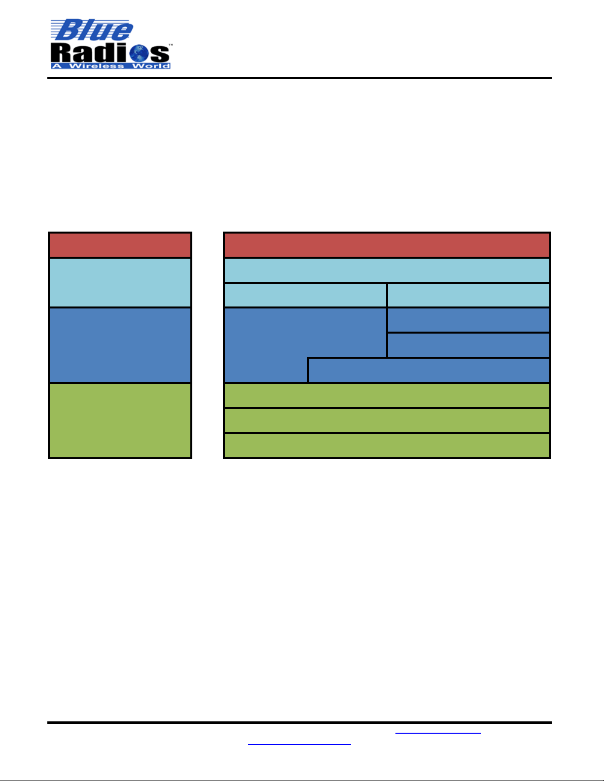
1.3 LE Protocol Stack
The BT5.0 low energy protocol stack is built similarly to the BR/EDR stack, with a controller layer at the bottom,
followed by a host layer, and finally the profile and application layers. The GAP and GATT layers and above are
the only layers that should concern the user. The GAP layer controls device discovery, advertising, and
connections. The GATT layer handles the exchanging of data.
The
n
Blue™modules contain a full stack all the way up to the application layer as seen below. The ATBLE API
contains all the necessary commands to enable the user to quickly and easily develop a fully featured BLE
application.
Simplified Stack Detailed Stack
GAP/Security Manager
Physical Layer (PHY)
Link Layer (LL)
Host Controller Interface (HCI)
L2CAP
ATT
GATT
GATT Profiles
GAP Role Profiles (M/S)
n
Blue™AT API
User Application
Application/Profile
Layers
Host Layers
Controller Layers
User Application

Page 14 of 195
AT.s LE Command Set v5.1.1b
Copyright © 2002-2021 BlueRadios, Inc.
200 S. Wilcox St., Unit 158 • Castle Rock, CO 80104 • USA • 303-957-1003 • sales@blueradios.com
www.BlueRadios.com
BT5.0 New Features
New LE Physical Layers (PHYs)
BT5.0 supports 3 different LE physical layers (PHYs): 1Mbps Standard (1M), 2Mbps High Speed (2M) and
125kbps Coded Long Range (LR). Non-extended advertising (4.0 advertising) is done on the 1M PHY only,
whereas the new 2M and LR PHYs can be used for extended advertising. Once connected any of the 3 PHYs can
be used if both sides of the connection support it.
1M: The 1Mbps PHY is the standard PHY used by BT4.0 and must be supported by a BT5.0 device.
2M: The 2Mbps PHY is a new optional PHY that provides double the speed of the 1M PHY. This increase in
speed may not be noticeable when streaming over BRSP, as our testing has shown both 1M and 2M PHYs maxed
out at ~50kBps when streaming in one direction. But if streaming large amounts of data bi-directionally the 2M
PHY will provide the highest throughput (~45kBps vs ~35kBps). Regardless of the speed increase, the 2M PHY
can be a better choice in a short distance environment. Due to the increased symbol rate of the 2M PHY the radio
on time will be reduced since the data is being sent in a shorter amount of time, but this will also decrease the link
budget so it will have shorter range than either the 1M or LR PHYs.
LR: The 125kbps Coded PHY is a new optional PHY that provides 4x the range by using Forward Error Correction
(FEC). The increased range comes at the cost of throughput since the coding scheme replaces each bit with 8
bits. When streaming over BRSP the maximum data rate in one direction will be ~5kBps and ~4kBps when
streaming bi-directionally.
1.3.1.1 BRSP Throughput for Different PHYs
Measurements were taken when streaming either with the UART at 921600 baud or through USB with a default
MTU of 247 and default connection interval of 20ms. Using a lower baud rate for the UART will limit the
throughput to the baud rate itself.
Single Direction
Bi-Directional
1M
50 kBps
35 kBps
2M
50 kBps
45 kBps
LR
5 kBps
4 kBps
Extended Advertising
When advertising using the new extended advertising format up to 255 bytes can be sent in one advertising
packet. Extended advertising takes place in 2 stages and a different PHY can be used for each stage. First
ADV_EXT_IND packets are sent out on the primary PHY on the standard advertising channels (37, 38 and 39).
These packets do not include any advertising data but indicate to the receiver what secondary PHY and channel
the extended advertising packet will be sent on. The actual extended advertising packet will go out on one of
channels 0-36, which are the same channels used for data during a connection. For the primary PHY either 1M or
LR can be selected, but the 2M PHY cannot be used as the primary PHY. For the secondary PHY any PHY may
be selected. If a connection is made to a device that is advertising using a connectable extended advertisement,
then the secondary PHY is the PHY that the connection will be established on.
LE Secure Connections Pairing (LESC)
LE Secure Connections Pairing uses the Elliptic-Curve Diffie-Hellman (ECDH) algorithm for key generation during
the pairing process to secure it from passive eavesdroppers in all instances. Both devices that are pairing must
support LESC for it to be used. For protection against Man in the Middle attacks authentication should still be
enabled. When authentication is enabled and the IO_Capabilities support it, a passkey will need to be confirmed
on both sides during the pairing process when using LESC. This is a slightly different process than the passkey
display and passkey response used when LESC is not enabled.

Page 15 of 195
AT.s LE Command Set v5.1.1b
Copyright © 2002-2021 BlueRadios, Inc.
200 S. Wilcox St., Unit 158 • Castle Rock, CO 80104 • USA • 303-957-1003 • sales@blueradios.com
www.BlueRadios.com
Important Notes –Please Read Prior To Continuing
2.1 Important Notes
▪The module can be powered in normal voltage mode (1.7-3.6V) or high voltage mode (2.5-5.5V). In
normal voltage mode, 1.7-3.6V is connected to both VDD and VDDH. In high voltage mode, 2.5-5.5V
is connected only to VDDH and in this case VDD will become the output of the internal VDDH
regulator (AT.s firmware sets the VDDH output to 3.3V, but the 52840 defaults to 1.8V). In either
power mode the voltage on the VDD pin will be the IO voltage, so the IO voltage can never be
higher than 3.6V and is not 5V tolerant even when using VDDH. Due to an issue with Rev 1 of the
nRF52840, high voltage mode can only be used under the following conditions: the VDDH internal
DCDC converter cannot not enabled (default LDO mode only), no current is drawn from the VDD
pin during power up and the VDDH rise time to 3V is < 1ms. This will be fixed in the next nRF52840
revision. See Errata 197 and 202 of the nRF52840 Rev 1 Errata for more info:
https://infocenter.nordicsemi.com/index.jsp?topic=%2Ferrata_nRF52840_Rev1%2FERR%2FnRF52840%
2FRev1%2Flatest%2Ferr_840.html
▪If migrating from a pre-5.0 module, please thoroughly read the Revision History to learn about the
changes made since the previous AT.s Command Set 3.5.
▪Over the air updates are enabled by default through the DFU service. If you do not want to allow
updating the module over the air, this feature can be disabled through ATSDFU.
▪Remote command mode is enabled by default, allowing AT commands to be sent to the device
over the air through the BRSP service. If you do not want remote command mode enabled, it can
be disabled using ATSBRSP.
▪Before proceeding, use the ATV? command to read the firmware version of your modules. Make sure the
rsion matches the first two digits of the version of this document.
If the module is running older firmware, newer firmware or the command set document corresponding to
the older firmware can be found on blueradios.com/forum.
▪The BT5.0 Address and address type have now been combined into a single parameter for all
commands/events using an address. See BT5.0 Address Format for more details.
▪BRSP throughput can now reach speeds of up to 50kBps between two BR-LE5.0-S1 or PAN1780-AT
modules when the MTU is set to 247 bytes. When connecting a BR-LE5.0-S1 or PAN1780-AT to an older
BR-LE4.0 module the MTU will be 23 and the maximum BRSP throughput will be 1.3kBps.
▪To achieve higher data throughput the BR-LE5.0-S1 and PAN1780-AT module supports higher MTUs
(Maximum Transmission Units) than the default value of 23 used by our older modules. To use a higher
than default MTU two connecting devices must perform an MTU exchange to find out what MTU both
sides can support. Once this exchange is complete and an MTU has been set an MTU event will be sent.
An MTU exchange is a GATT request, so GATT commands cannot be sent until the MTU event has
occurred. If both devices being connected have their MTU set to 23 which is the minimum, then an MTU
exchange will not be attempted and the MTU event will never occur.
▪Any events that are unused or unwanted can now be disabled using the ATSRM command.

Page 16 of 195
AT.s LE Command Set v5.1.1b
Copyright © 2002-2021 BlueRadios, Inc.
200 S. Wilcox St., Unit 158 • Castle Rock, CO 80104 • USA • 303-957-1003 • sales@blueradios.com
www.BlueRadios.com
2.2 Backwards Compatibility
▪To provide the best firmware architecture, design, and future profile support 100% backwards compatibility
between releases cannot be guaranteed.
2.3 Known Issues
Version 5.0.2.0:
▪When pairing with another device for the first time, the internal pairing database does a GATT read of the
Central Address Resolution characteristic. This GATT read occurs at the time the PAIRED event is sent
and completes 30-50ms later (when using the default connection interval of 20ms). If a GATT command is
sent in this time frame it will fail with ERROR,12 indicating a GATT request is already pending.
2.4 Related Applications
▪nBlue Programmer - nBlueProgrammer (nBP) is a Windows application that allows firmware to be
updated on all BlueRadios® nBlueBT4.0/5.0 moduless
UART, USB and Over the Air (OTA) through a BLE connection (see the OTA updates section for additional
requirements.)
▪nBlue iBeacon Configuration Tool - nBlueiBeacon Configuration Tool (nBiBCT) is a Windows
application that allows BlueRadios® nBlueBT4.0/5.0 modules to be configured as iBeacons.
▪nBlueTerm nBlueTerm is an iOS application that allows an iOS device to communicate with all
BlueRadios® nBlueBT4.0/5.0 modules over BRSP in both data and remote command modes. It is
available to download for free from the Apple App Store.
2.5 Related Documents
▪n
▪nBlue BR-EVAL-5.0-S1 Quick Start Guide
▪nBlue
▪nBlue iBeacon

Page 17 of 195
AT.s LE Command Set v5.1.1b
Copyright © 2002-2021 BlueRadios, Inc.
200 S. Wilcox St., Unit 158 • Castle Rock, CO 80104 • USA • 303-957-1003 • sales@blueradios.com
www.BlueRadios.com
Hardware Notes
This section is meant to provide a summary of the hardware specifications and details of specific AT.s hardware
The BR-LE5.0-S1 utilizes the Nordic nRF52840 SoC, for detailed specifications see the product specification:
https://infocenter.nordicsemi.com/index.jsp?topic=%2Fps_nrf52840%2Fkeyfeatures_html5.html
3.1 Power Modes
** IMPORTANT **: The module can be powered in normal voltage mode (1.7-3.6V) or high voltage mode
(2.5-5.5V). In normal voltage mode, 1.7-3.6V must be connected to both VDD and VDDH. In high voltage
mode, 2.5-5.5V is connected only to VDDH and in this case VDD will be the output of the internal VDDH
regulator (AT.s firmware sets the VDDH output to 3.3V, but the 52840 defaults to 1.8V). In either power
mode the voltage on the VDD pin will be the IO voltage, so the IO voltage can never be higher than 3.6V
and is never 5V tolerant even when using VDDH. See the Internal Regulator Diagram on the next page for
a visual on how the regulators connect.
** IMPORTANT **: Due to an issue with Rev 1 of the nRF52840, high voltage mode can only be used under
the following conditions: the VDDH internal DCDC converter cannot not enabled (default LDO mode only),
no current is drawn from the VDD pin during power up and the VDDH rise time to 3V is < 1ms. This will be
fixed in the next nRF52840 revision. See Errata 197 and 202 of the nRF52840 Rev 1 Errata for more info:
https://infocenter.nordicsemi.com/pdf/nRF52840_Rev_1_Errata_v1.1.pdf
* VBUS *: To use the BR-LE5.0-S1A as a USB peripheral, 5V must be supplied on the VBUS pin. The VBUS
supply is internally regulated to 3.3V but is only used for the USB signaling interface and USB detection. The rest
of the USB peripheral is powered through the main power supply, so power must still be supplied through VDDH or
VDD depending on what power mode is being used. When supplying power from a USB source only, VBUS must
be connected to VDDH if USB is to be used.
3.2 Electrical Specifications Summary
Item
Specifications
Supply voltage (VDD)
1.7-3.6 V
VDD Supply rise time (0V to 1.7V)
60ms
Supply voltage (VDDH –Optional)
2.5-5.5 V
VDDH Supply rise time (0V to 3.7V)
100ms
Supply voltage (VBUS - Optional)
4.35-5.5 V
Supply ripple
100 mV Max
Max I/O pin voltage
VDD + .3V, 3.9V Max (Not 5V Tolerant)
Ambient Temperature Range
-40 85 °C
3.3 Power-up and Reset
There are no strict requirements for power up timing. The module is ready to receive commands once the RESET
event is sent out of the UART or USB Serial Port. This event is sent over the UART approximately 850ms after
power on. To reset the module, the RESET line must be pulsed low for at least 1µS.
3.4 Default IO States
PIOs 2,5,7,8,16 (RTS) and 17(TX) default to outputs. PIOs 3,4,6,14,15 (CTS) and 18 (RX) default to inputs with
3,4,6 and 14 pulled low for the BR-LE5.0-S1 or high for the PAN1780-AT. All other inputs default to the
disconnected state.

Page 18 of 195
AT.s LE Command Set v5.1.1b
Copyright © 2002-2021 BlueRadios, Inc.
200 S. Wilcox St., Unit 158 • Castle Rock, CO 80104 • USA • 303-957-1003 • sales@blueradios.com
www.BlueRadios.com
3.5 PIO Functions
NOTE: The LEDs (PIO_2/5/7/8) and buttons (PIO_3/4/6/14) on the PAN1780-AT are inverted compared to the
BR-LE5.0-S1A.
PIO_2/5/7/8 Status Indicators Outputs
PIO_2 and PIO_5 are defaulted to outputs used to indicate the current status of the module. By default, they
will behave in the following manner. PIO_2 will pulse at a configurable duty cycle and rate when the module is
connected to another device. PIO_5 will pulse at a configurable duty cycle and rate when the module is
advertising, discovering, or connecting. When the module is idle both PIOs will output logic low for the BR-
LE5.0-S1 or logic high for the PAN1780-AT. Both can be configured using the ATSLED/ATSPIO commands.
PIO_7 can be configured via the ATSZ command to indicate when the module is in sleep mode or low power
mode. PIO_8 will flash when a command is received to confirm communication with the dev board. PIO_7/8
can also be overridden to blink at a user specified rate using ATSLED.
PIO_3 - Sleep Mode Toggle Input
PIO_3 is used to toggle the module in and out of sleep mode. PIO_3 needs to be pulsed high for the BR-LE5.0-
S1 or low for the PAN1780-AT for at least 1ms. Since the UART is shutdown when the device enters sleep
mode, RTS will be set high when sleep mode is enabled, and upon waking up RTS will go low. ATSZ can be
used to also configure PIO_5 to go low on the BR-LE5.0-S1 or high on the PAN1780-AT when the module is
sleeping and high on the BR-LE5.0-S1 or low for the PAN1780-AT when it is awake.
If PIO_3 is held high on the BR-LE5.0-S1 or low for the PAN1780-AT for 500ms, shutdown will be enabled, and
the module will enter its lowest power state where it can only be woken back up by a reset or by pulsing PIO_3
(which will trigger a reset). In this state the UART and all BT5.0 functionality will be disabled, but the current
state of the PIOs at the time of the shutdown will be maintained.
PIO_4 - Factory Reset / Connection Control Input
PIO_4 has multiple purposes. First, it can be used to factory reset the module by setting it to VDD on the BR-
LE5.0-S1 or GND on the PAN1780-AT during power up or reset and holding it at VDD on the BR-LE5.0-S1 or
GND on the PAN1780-AT Secondly, it can
be used as a hardware shortcut to reconnect and disconnect when pulsed high on the BR-LE5.0-S1 or low for
the PAN1780-AT for at least 1ms.
▪Pulsing PIO_4 while not connected will perform an ATDMLLE to connect to the last connected device.
▪If already connecting, pulsing PIO_4 will perform an ATDC to cancel connecting.
▪Pulsing PIO_4 while connected will perform an ATDH to disconnect.
▪The module will respond with the same response as if the command was entered through the UART.
PIO_6 - BRSP Comm Mode Toggle Input
PIO_6 can be used as a hardware shortcut for toggling between command mode and data mode when
connected by pulsing it high on the BR-LE5.0-S1 or low for the PAN1780-AT for at least 1ms. The module will
respond with the same response as if the command was entered through the UART.

Page 19 of 195
AT.s LE Command Set v5.1.1b
Copyright © 2002-2021 BlueRadios, Inc.
200 S. Wilcox St., Unit 158 • Castle Rock, CO 80104 • USA • 303-957-1003 • sales@blueradios.com
www.BlueRadios.com
PIO_14 - Firmware Upgrade Mode / Advertising Control Input
PIO_14 has multiple purposes. First, it can be used to manually put the module into firmware upgrade mode
by setting it to VDD on the BR-LE5.0-S1 or GND on the PAN1780-AT during power up or reset by holding it at
VDD on the BR-LE5.0-S1 or GND on the PAN1780-AT UART.
Secondly, it can be used as a hardware shortcut to control advertising when pulsed high on the BR-LE5.0-S1
or low for the PAN1780-AT for at least 1ms.
▪Pulsing PIO_14 while not advertising will perform an ATDSLE to start advertising.
▪If already advertising, pulsing PIO_14 will perform an ATDC to cancel advertising.
▪The module will respond with the same response as if the command was entered through the UART.
3.6 UART Interface
UART_TX, UART_RX, UART_RTS and UART_CTS form a conventional asynchronous serial data port. Two-
way hardware flow control is implemented by UART_RTS and UART_CTS. These signals operate according
to normal industry convention. The signaling levels are nominal 0V and VDD and are inverted with respect to
the signaling on an RS232 cable. The interface is programmable; the baud rate, stop-bits, parity, and flow
control can all be configured through the ATSUART command. If the module is not connected to another
UART, RX should be pulled high to keep it from floating.
3.7 USB Interface
In addition to the UART, the module can also be controlled using AT commands through a USB CDC ACM
virtual serial port. The module can be controlled through this port through AT commands and events in the
same way it can over the UART.

Page 20 of 195
AT.s LE Command Set v5.1.1b
Copyright © 2002-2021 BlueRadios, Inc.
200 S. Wilcox St., Unit 158 • Castle Rock, CO 80104 • USA • 303-957-1003 • sales@blueradios.com
www.BlueRadios.com
Lowering Power Consumption
4.1 Sleep Mode
commands over the air using BRSP Remote Command Mode). To receive commands and data via the UART,
the UART needs to be active and for
er is in the active
state by allowing the user to tell the module when the UART needs to be active.
When sleep mode is enabled the module will enter the lowest possible power state it can based on the current
state and configuration of the module. By default, the module will not be in sleep mode upon power up, but for
maximum power savings it should be put into sleep mode as soon as possible after all configuration is complete
and kept in sleep mode as often as possible per the application.
While in sleep mode the module will not be able to receive data on the UART but will still be able to handle RF
tasks. This allows any active connection requests, discovery request, advertising requests, or connections to
be maintained in the background, with the module sleeping in between RF events. The module can still receive
incoming data over the air and output it on the UART while it is in sleep mode.
Sleep mode will not affect the operation of the USB serial port.
Enabling/Disabling Sleep Mode
Sleep mode can be enabled by executing the ATZ command or by pulsing PIO_3 high on the BR-LE5.0-S1 or
low for the PAN1780-AT while the module is awake. ATSZ can also be used to configure the module to
automatically enter sleep mode on power up or after a reset.
Sleep mode can be disabled by pulsing PIO_3 high on the BR-LE5.0-S1 or low for the PAN1780-AT while the
module is asleep. ATSZ can be used to configure the module to wake up in response to a high to low
transition on the UART_RX line. This allows the module to be woken up by sending a character over the UART,
ough to receive this
character.
PIO_3 needs to be pulsed high on the BR-LE5.0-S1 or low for the PAN1780-AT for at least 1ms to toggle in
and out of sleep mode.
UART and Sleep Mode
When the module is in sleep mode it will not be able to receive data on the UART, so it will not be able to accept
any data or AT commands. Since the UART receiver is shutdown when the device enters sleep mode, RTS
will be set high when entering sleep mode, and upon waking up it will go low.
Keep in mind that only the UART receiver is disabled by sleep mode, not the UART transmitter. The module
can still receive incoming data over the air and output it on the UART while it is in sleep mode. Events will also
be sent while in sleep mode, so for example an ATDILE command could be executed followed by an ATZ and
the DISCOVERY events will still be sent, even though the module is in sleep mode.
Remote Commands and Sleep Mode
Since connections are maintained in the background while sleep mode is enabled, modules can be controlled
through AT commands sent over BRSP in Remote Command Mode. See the ATMRC command for more
information.
Table of contents
Popular Control Unit manuals by other brands


Valon
Valon 5015 Operation manual

Swagelok
Swagelok RHPS Series user manual

KIESELMANN
KIESELMANN 5093 Series Operating instruction

Aventics
Aventics AS1 operating instructions

SMC Networks
SMC Networks S0700 Installation and maintenance manual

Emerson
Emerson White Rodgers 36C53 Series installation instructions

Lenze
Lenze EtherNet/IP E84AYCEO Mounting instructions

Ossur
Ossur Icelock Alloy 4-Hole 674 Instructions for use

VAT
VAT 150 Series Installation, operating, & maintenance instructions

ZIEHL-ABEGG
ZIEHL-ABEGG CBG-30AV operating instructions

Siemens
Siemens HTRI-M installation instructions

Apacer Technology
Apacer Technology EFC-D Series user manual