10 Multi Floor Controller PK3661 03-19
4.0 System Installation Overview
A
U
T
S
X
Figure 6 OR
Step 5: Mounting the Quantum RFID ECU reader
Figure 7
1. Remove the back plate and use it to mark the
holes for the cables and screws.
NOTE: Refer to annex H of this manual for elevator
panel preparation for mounting reader.
2. Drill the holes in the wall according to the
diameters indicated on the drilling template
in Annex H, based on the type of surface the
reader is being installed on.
Refer to RCU/ECU installation instructions
Step 6: Connect peripheral wiring
CAUTION
Do not exceed the maximum cable length indicated
by the manufacturer of the products being
connected. In addition, the wire used to connect the
peripherals to controller PCB must be of the proper
gauge and type as specified by the manufacturer.
IMPORTANT
Every wire must pass through a strain relief as
connected in step 3
IMPORTANT
dormakaba does not provide technical or field
support for 3rd party locking devices. Please
consult the device manufacturer for support.
NOTE: The Maximum Recommended Wire Length
is the approximate wire length that causes
a 5% voltage loss in the wire, using a 12-volt
locking device at the rated current included.
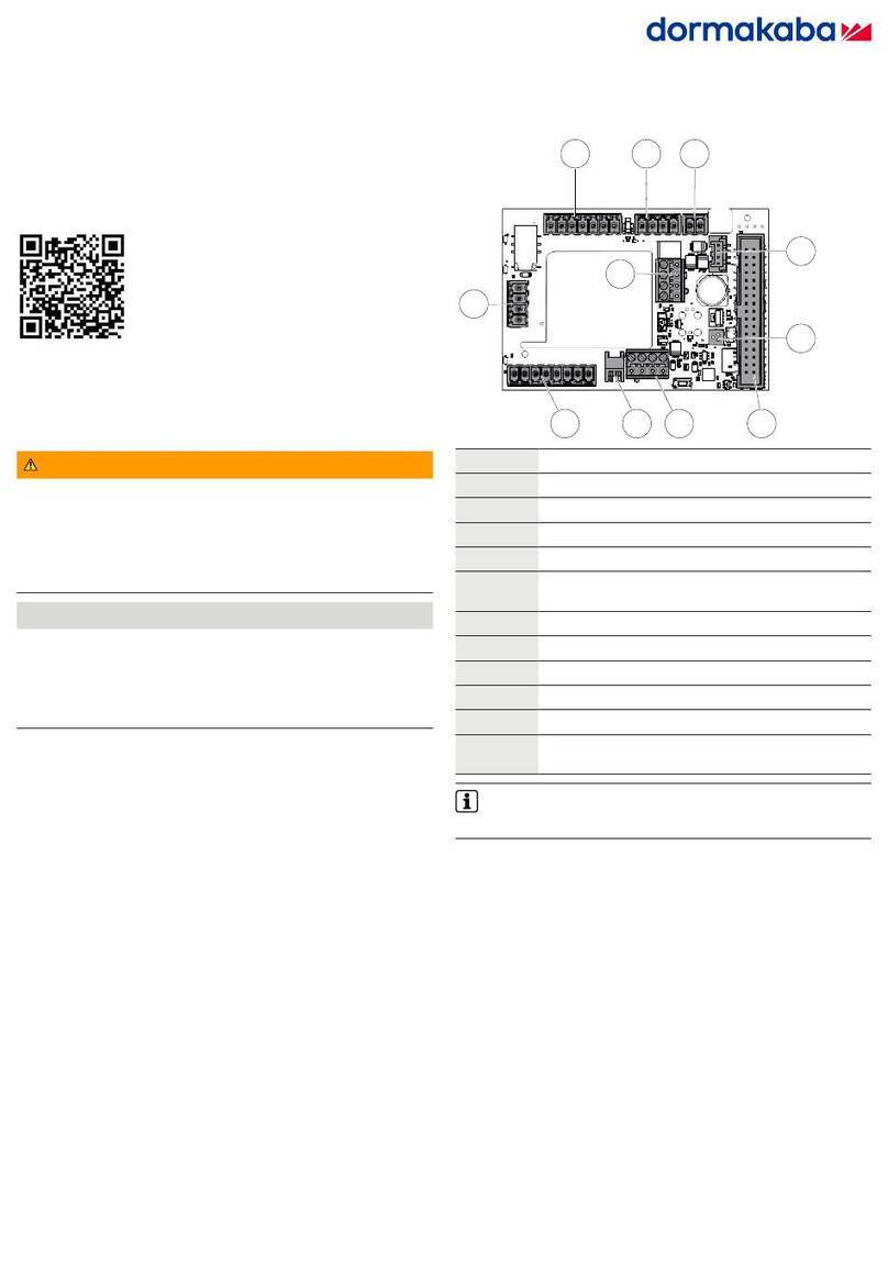
1. Fire Alarm Panel
Refer to Annex A, Figure 10 for detailed wiring.
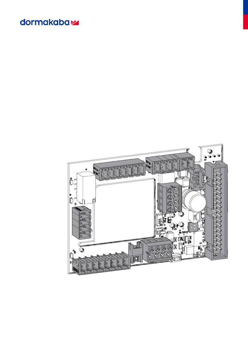
Remove the jumper wire connected between pins
3 and 4 of connector J18 on the controller PCB
and complete the fire panel installation as per
manufacturer’s indications.
2. Tamper Switch to Premise Alarm
System
To wire the tamper switch to the premise alarm
system disconnect the wires on controller PCB
connector J7 pins 1 & 2, and run a 2-connector cable
from the switch to the premise alarm system.
IMPORTANT
The tamper alarm switch’s polarity is such that
when the door is closed the switch itself is also in a
closed state. Ensure that the wiring to the premise
alarm system is done accordingly to prevent false
alarms.
Step 7: Relay Expansion Board outputs wiring
Refer to Annex B, for sample wiring diagram.
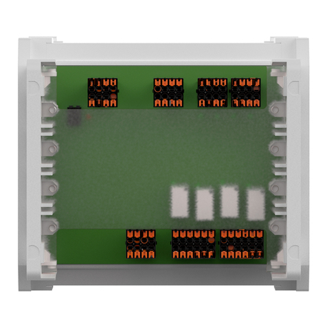
The relay expansion board provides 8 relay contacts
for wiring & control of relay-enabled elevator. The
board only provides normally open or normally
closed dry contacts, so no power is provided by the
board.
As wiring of relay-controlled equipment may vary
between products please refer to the product
manufacturer’s instruction booklet for proper
instructions.
NOTE: Refer to Annex B, table 4 for specific relay
expansion board bypass switches.
- If bypass switches are ‘ON’, the relays are
bypassed and the green LED associated with
that relay is turned OFF.
- If bypass switches are ‘OFF’ the controller PCB
can activate the relays. The associated LEDs
turn OFF during relay activation.
NOTE: When the power to the MFC-X is too low
(power failure, the controller PCB stops
functioning and the relays on the controller
PCB or the expansion board will return to
their normal state. Any peripheral connected
to the relays will then be either in a normally
open (NO) or normally closed (NC) state,
dependent on the wiring.
