Blue Sea VSM 422 Manual
Innovative marine electrical products—Built to Last
VSMVSMVSM
422
422
• Four meters in one
- AC Multimeter
- DC Multimeter including Amp Hours
- Tank Monitoring
- Bilge Cycling
• Twenty-two measurements
• Fifteen programmable alarms
Phone: 360-738-8230
Customer Service: Toll Free 1-800-222-7617
Fax: 360-734-4195
Internet Address: www.bluesea.com
Head Office Address: 425 Sequoia Drive
Bellingham, Washington 98226 USA
990470210 Rev. 001
Installation and Configuration Manual
1800
Blue Sea Systems VSM 422 Installation and Configuration Manual

Table of Contents
Installation Checklist 1
Specications 2
Warning and Cautions 3
System Overview 4
Mounting Considerations and Installation Notes 5
Detailed Wiring 6
Connections 7
Sensors 8
User Interface Overview 10
Main Display Structure 11
Initial System Setup 13
OptionalInputConguration 15
UnitsofMeasureSetup 17
ACSystemConguration 19
DCSystemConguration 21
TankConguration 25
StateofChargeConguration 47
BilgePumpConguration 51
Display Setup
BacklightTimeSetup 53
SystemSummarySetup 55
GraphicsSummarySetup 57
Table of Contents
Alarm Setup 61
BatteryVoltageAlarmSetup 63
DCCurrentAlarmSetup 65
ChargePercentageAlarmSetup 67
BatteryTemperatureAlarmSetup 69
ACCurrentAlarmSetup 71
ACVoltageAlarmSetup 73
ACFrequencyAlarmSetup 75
BilgeCycles/24HoursAlarmSetup 77
RunTime/HourAlarmSetup 79
TankAlarmsSetup 81
Reset
BilgeCycleReset 83
BatteryCycleReset 85
StateofChargeDefaultsReset 87
RestoreFactoryDefaults 89
Troubleshooting 91
EC Declaration of Conformity 92
Warranty and Warranty Registration 93
Tank Level Sender Installation Diagrams 94
Installation Diagram 95

INSTALLATION CHECKLIST
0CheckforpartsshownonfrontofQuickStart
Installation Guide
0ReadWarningandCautions(page3)
0ReadQuickStartInstallationGuidefor
mountinginstructions
0ReadSystemOverview,MountingConsiderations,
DetailedWiring,andSensingDescription(pages4–9)
0ReadQuickStartInstallationGuidefor
installation notes
0FollowInitialSystemSetupinstructions(page13)
0CongureDisplays(page53)
0CongureAlarms(page61)
1 Specicationssubjecttochange.Seewww.bluesea.comforcurrentinformation.
SPECIFICATIONS
2
DC Specications:
NominalSystemVoltage 12or24Volts
OperatingVoltage 8.5–33.0Volts
MinimumCurrentDraw [email protected]Volts,18.8mA@24Volts
VoltageAccuracy +/-0.5%
CurrentRange 0–500Amps
CurrentAccuracy +/-1.0%
AC Specications:
NominalSystemVoltage 120Volts@60Hz—NorthAmerica
230Volts@50Hz—TypicalofEurope
OperatingVoltage 0–300Volts
VoltageAccuracy(RMS) +/-0.5%
CurrentRange 0–150Amps
CurrentAccuracy(RMS) +/-2.0%
Frequency 40–90Hz
Regulatory
ECDeclarationofConformity(page92)
VSM422SurfaceMountGasketcreatesanIP67waterproofsealonunit
face—temporaryimmersionfor30minutes
NOTE: Panel mount congurations are not waterproof.
Magnetic Compass Deviation
Compasssafeworkingdistanceis10.00"(250mm)fromVSM422HeadUnit.
RESOURCE INFORMATION
Application Briefs:
StateofCharge(SOC) http://bluesea.com/viewresource/1324
ACCurrentMeasurement http://bluesea.com/viewresource/86
Specicationssubjecttochange.Seewww.bluesea.comforcurrentinformation.

CAUTION
WARNING
TheWARNINGsymbolreferstopossibleinjurytotheuserorsignicant
damagetothemeteriftheuserdoesnotfollowtheprocedures.
3
WARNING
]VerifythatallACsourcesaredisconnectedbeforeconnectingor
disconnectingthecurrenttransformer.Failuretodosowill
generatelethalvoltagesonthecurrenttransformer.
]Ifyouarenotknowledgeableaboutelectricalsystems,havean
electricalprofessionalinstallthisunit.Thediagramsinthese
instructionspertaintotheinstallationoftheVSM422andnottothe
overallwiringofthevessel.
]Ifaninverterisinstalledonthevessel,itspowerleadsmustbe
disconnectedatthebatterybeforetheunitisinstalled.Manyinverters
havea“sleepmode”inwhichtheirvoltagepotentialmaynotbe
detectablewithmeasuringequipment.
]IfanACgeneratorisinstalledonthevessel,itmustbestoppedand
renderedinoperablebeforetheunitisinstalled.
]VerifythatnootherDCorACsourcesareconnectedtothevessel’s
wiringbeforeinstallingtheunit.
]Ifthemetermustberemoved,connectthecurrenttransformerleads
togetherbeforerestoringpowertotheACsystem.
]Thebackoftheunitisnotwaterproof.Donotinstallwherethebackof
themeterisexposedtowater.
WARNING AND CAUTION SYMBOLS
CAUTION
TheCAUTIONsymbolreferstorestrictionsandruleswithregard
topreventingdamage.
Specicationssubjecttochange.Seewww.bluesea.comforcurrentinformation.
SYSTEM OVERVIEW
Optional Input:
Thepinthreeconnectioncanbeconguredasoneofthreeoptions:athird
tank,athirdbattery,orbilgemonitoring.
AC Functions:
TheACsystemallowsformonitoringoftheACvoltage,frequencyand
currentlevels.Highandlowalarmscanbeconguredforeachofthese.
DC Functions:
TheDCsystemmonitorsthevoltagelevelsonuptothreebatteries,aswell
asthecurrentdrawonthebatteryonwhichstateofchargeisbeing
monitored.Highandlowlimitscanbesetforthevoltageoneachbattery.
AhighcurrentalarmcanalsobesetonthebatterymonitoredforState
ofCharge.
State of Charge (SOC):
StateofChargegivesfeedbackonhow“full”thebatteryiswithusable
energy.Thesystemkeepstrackoftheamphours(Ah)remainingonthe
battery,thechargecyclesonthebattery,andthetemperatureofthebattery.
LowStateofChargeandhighbatterytemperaturealarmscanbeset.With
thelowstateofchargealarmset,theVSM422showsthetimeremaining
untilthealarmwillactivate,atboththecurrentpowerusageandatthe
averagepowerusageforthelast20minutes.
Tank Functions:
TheVSM422iscapableofmonitoringuptothreetanks.Thesystemhasan
autocalibrationroutineforgeneratingatankshapeprolefor
non-rectangulartanks.Tankstatuscanberepresentedinbothcapacity
(gallonsorliters)orasapercentageofcapacity.Anti-sloshroutinesarebuilt
intoincreaseaccuracyofreadings.Bothhighandlowlevelalarmscanbe
setforalltanks.
Bilge Functions:
TheVSM422monitorsthecurrentrunstatusofthepump,thetimerunning
inthelasthour,thecyclesinthelast24hours,andthetotalcyclessincethe
lastcyclereset.Highalarmscanbesetforboththeminutesofruntimein
thelasthour,aswellasthenumberofcyclesinthelast24hours.
4
Specicationssubjecttochange.Seewww.bluesea.comforcurrentinformation.
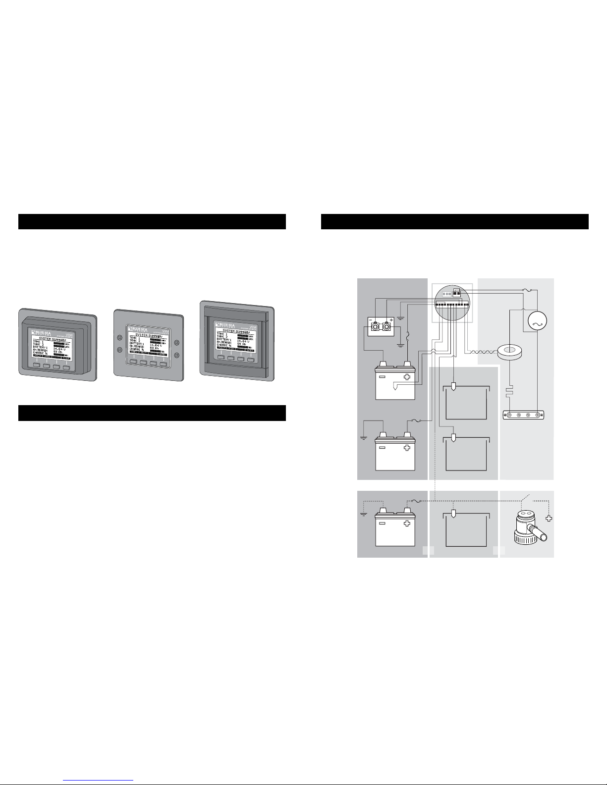
MOUNTING CONSIDERATIONS
TheVesselSystemMonitorhasthreemountingmethods:surfacemount,
atpanelmount,and360panelmount.Whensurfacemountedusingthe
suppliedgasket,anIP67waterproofratingiscreatedforthefrontoftheunit.
Becausepanelmountingsystemsarenotwaterproof,theunitshouldnotbe
panelmountedinanexposedlocation.Forallmountings,thebackofthe
unitisnotwaterproofandmustbekeptdry.
Surface Mount Flat Panel Mount
5
360 Panel Mount
INSTALLATION NOTES
1.Theunitmustbeconnectedtoanon-switchedcircuittoensureaccurate
andconsistentStateofChargemonitoring.
2.Makeallconnectionstotheunit’sterminalblockbeforeconnectingthe
terminalblocktotheunit.Keephandsawayfromtheterminalblockwhen
applyingpowertotheunit.
3.AsthenalDCconnection,insertafuseintothein-linefuseholderon
thewiretothepositivebatteryterminal.
Specicationssubjecttochange.Seewww.bluesea.comforcurrentinformation.
DETAILED WIRING
IMPORTANT!TheSensingDescriptionsectionofthismanualgives
importantdetailstothelocationofsensorsintheACandDCelectrical
systemsoftheboat.Improperlocationandcongurationofsensorscan
resultinerroneousreadingsandpossibledamagetocomponents.
6
DC SYSTEM AC SYSTEM
TANKS
Battery 1
Voltage
Battery 2
Voltage
Battery 3
Voltage
Battery Temp
Battery 1
Battery 2
Select one optional input
Battery 3
Tank 1 Level
Tank 2 Level
Tank 3 Level
Tank 1
Tank 2
Tank 3 Bilge Switch
AC
Voltage
and
Frequency
AC
Load
DC Current
AC
+/- Amp
Hours
AC Current
H
N
OR OR
Specicationssubjecttochange.Seewww.bluesea.comforcurrentinformation.

CONNECTIONS
Connector Function
Header A Communication*
Pin1 Communication
Pin2 Communication
Pin3 Communication
Header B AC
Pin1 AC Line
Pin2 ACNeutral
Header C Sensors and Power
Pin1 DCVoltageBattery1(UnitPower)†
Pin2 DCVoltageBattery2
Pin3‡DCVoltageBattery3,TankLevel3,orBilgeFunction
Pin4 DCNegative
Pin5 BatteryTemperature(Positive)
Pin6 BatteryTemperature(Negative)
Pin7 TankLevel1
Pin8 TankLevel2
Pin9 DCShunt(Positive)
Pin10 DCShunt(Negative)
Pin11 ACCurrentCoil(Positive)
Pin12 ACCurrentCoil(Negative)
*Communicationportisforusewithfuturemodules
†AmperehoursaremeasuredforBattery1ONLY
‡Threeinputoptionsavailable
7
A
B
1
112
3
12
C
2
2345678910 11
Connector Pin Assignment Table
Specicationssubjecttochange.Seewww.bluesea.comforcurrentinformation.
SENSORS
DC Current
TheshuntmustbeplacedbetweenthenegativeterminalonBattery1and
themainnegativebus.All loads and charge sources should have their
negative terminals on the main negative bus,withtheexceptionoftheVSM
422negativesourcewhichmustbeconnecteddirectlytothebatterysideof
theshunt.ShuntsensewiresmustbeatwistedpairfromshunttoVSM422
forpropercalculationofStateofCharge(SOC).Twistedpairwirecanbe
purchasedfromelectricalsupplycompanies,ormadebytwistingbyhand
orwithanelectricdrillmotor.ThecurrentreadingforBattery1whenitisnot
beingchargedandhasaloadshouldbenegative.Ifitisnot,reversetheDC
shuntleads.(seepage95)
DC Voltage
VoltagelinestotheVSM422shouldbedirectlyconnectedtothepositive
batteryterminalwithadedicatedwireaheadofanyotherconnections.This
willensurecorrectvoltageandSOCmonitoring.Useanappropriatein-line
fuse(5Asuggested)onthepositivewire.
AC Current
InmostcasestheACCurrentTransformershouldbelocatedonthemain
ACfeedbeforeanyotherdevices.Seehttp://bluesea.com/viewresource/86
formoreinformationonACCurrentTransformerlocation.Thelocationdoes
notaffectstateofcharge(SOC)calculations.
TheCurrentTransformerdoesnotindicatepolarity.IfACvoltageisapplied
andcurrentshowsgreaterthanzerobutthepowerreadingiszeroora
negativevalue,reversetheACCurrentTransformerleads.Theleadsshould
betwistedtoreducetheeffectsofinterference.
AC Voltage
TheungroundedAClineshouldbefusedinlinewithafastactingfuseof
0.25Ato0.5Atoprotectagainstshorts.
Bilge Sensor
Connect“switchon”leadofbilgepumptotheVSM422unit.Thiswire
shouldread+12/24Vwhenrunningand0Vwhenoff.
8
Specicationssubjecttochange.Seewww.bluesea.comforcurrentinformation.

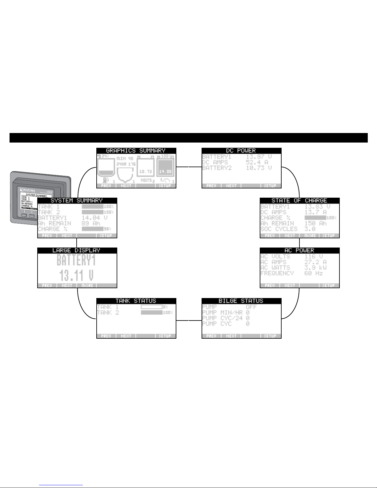
USER INTERFACE OVERVIEW
BOLDtextdesignatesabutton.
ItalicizedtextdesignatestextontheVSM422screen.
Theuserinterfaceiscontrolledbythefourbuttonslocatedbelowthe
display.Eachoneofthebuttonscorrespondstothetextatthebottomof
thescreen.
Systeminformationisdisplayedwitheightscreens:SYSTEM SUMMARY,
GRAPHICS SUMMARY,DC POWER,STATE OF CHARGE,AC POWER,
BILGE STATUS,TANK STATUS,andLARGE DISPLAY.
SomescreenssuchasSTATE OF CHARGE and LARGE DISPLAYhavea
MOREbutton;thiscanbeusedtocyclethroughtheinformationthatisnot
visibleononescreen.Insomesetupscreens<- and ->arrowswillbeshown.
Theseindicatethattheselectionoptionscontinueonascreenthatis
displayedwhentheuserhasscrolledpastthetoporbottomofthescreen.
Thedataeldsforbothsummaryscreenscanbecustomizedthrough
displaysetup.
10
Specicationssubjecttochange.Seewww.bluesea.comforcurrentinformation.
SENSORS (continued)
Temperature Sensor
ThebatterytemperaturesensorshouldbelocatedneartheStateofCharge
battery.Itcanbemountedtoabatteryboxusingthehole,orcable-tiedto
thenegativebatteryterminal.IMPORTANT! Do not fasten the Temperature
Sensor directly to the battery in any way that may puncture or damage
the battery.
Tank Sender
TheVSM422iscompatiblewiththreesenderprotocols.
Resistive 2 Wire Senders: (see page 94 for Installation Diagram)
10–180Ω VDO—TypicalofEurope
240–33ΩTeleex—NorthAmerica
Ultrasonic 3 Wire Senders: (see page 94 for Installation Diagram)
BlueSeaSystemsPN1810andPN1811.
BlueSeaSystemsultrasonicsenderPN1810isusedforwater,waste,and
dieselfueltanksupto32"(812mm)indepth.BlueSeaSystemsultrasonic
senderPN1811isusedforgasolinetanksupto24"(609mm)indepth.
Whenconnectingthetanksendertogrounditisimportanttoconnectthem
asdirectlyaspossibletothemainnegativebustopreventhighloadssuch
asbatterychargersfromaffectingthetankreadings.
TheVSM422willnotproduceaccuratereadingsifasecondgaugeis
connectedtothesametanksender.Installasenderforeachgaugeifyou
wishtoreadatanklevelfrommorethanonelocation.
TheBlueSeaSystemsultrasonicsenderrequiresanexternalpowersource.
Whenpowertothesenderislost,theVSM422willreadthetankasfull,and
maytriggerthetank’shighlevelalarm.
Foreachtankthesendermustbespecied,andtheshapeofthetank
setasrectangularorauto-calibratedbeforeaccuratereadingsaredisplayed.
9 Specicationssubjecttochange.Seewww.bluesea.comforcurrentinformation.
11
MAIN DISPLAY STRUCTURE
Specicationssubjecttochange.Seewww.bluesea.comforcurrentinformation. 12
Specicationssubjecttochange.Seewww.bluesea.comforcurrentinformation.

14
Specicationssubjecttochange.Seewww.bluesea.comforcurrentinformation.
13
INITIAL SYSTEM SETUP
Manysetupscreensrequirethattheuserenterdata.Therearetwomethods
ofenteringdata.
Scroll Bar Method:
Thenumbersontheleftandrightrepresentthehighandlowrangeofthe
valueselected,andthenumberinthemiddleisthecurrentvalue.Toadjust
thevalueusethe<- and ->buttons.Turnoffanalarmbyscrollingallthe
waytotheleftforalowlimitorallthewaytotherightforahighlimit.The
currentvaluewillshow OFF.PressingSELECT willsetthevalue;pressing
EXIT willcancelthechange.
Character Selection Method:
Changethevaluebyselectingthecharacterusingthe <- and ->buttonsand
pressingSELECTwhenthecharacterishighlighted.Thelefttwobuttons
thenbecomeA<-Z and A->Zifanameisbeingchangedor0<-9 and 0->9
ifanumberisbeingchanged.Usethesebuttonstochangetothedesired
valueforthecharacter.Numerals0through9andablankspaceare
availableafterZwhenthecharactersareinthe“name”mode. Press
SELECTtolockthecharacter.Thebuttonswillthenreturnto<- and -> and
anothercharactercanbehighlighted.Whenallofthecharactershavebeen
setpressEXIT.
Specicationssubjecttochange.Seewww.bluesea.comforcurrentinformation.

16
Specicationssubjecttochange.Seewww.bluesea.comforcurrentinformation.
15
Optional Input Conguration
Connectiontopin3onHeaderCcanbeconguredtooneofthreeoptions,
battery3monitoring,tank3monitoring,orbilgemonitoring.
1. PagethroughmainscreensbypressingNEXTuntilthe
SYSTEM SUMMARYpageisvisible.
2. PressSETUP
3. ScrolltoandpressSELECT on OPTIONAL INPUT
4. ScrolltoandpressSELECTondesiredoptionalinputforsystem.
5. PressEXITtoreturntomainsystemscreens.
Specicationssubjecttochange.Seewww.bluesea.comforcurrentinformation.

18
Specicationssubjecttochange.Seewww.bluesea.comforcurrentinformation.
1. PagethroughmainscreensbypressingNEXTuntilthe
SYSTEM SUMMARYpageisvisible.
2. PressSETUP.
3. ScrolltoandpressSELECT on Units of Measure.
4. ScrolltoandpressSELECTondesiredunitsystem.
5. PressEXITtoreturntomainsystemscreens.
17
Units of Measure Setup
Specicationssubjecttochange.Seewww.bluesea.comforcurrentinformation.

20
Specicationssubjecttochange.Seewww.bluesea.comforcurrentinformation.
19
AC System Conguration
1. PagethroughmainscreensbypressingNEXTuntilthe
SYSTEM SUMMARYpageisvisible.
2. PressSETUP.
3. ScrolltoandpressSELECT on AC Frequency.
4. ScrolltoandpressSELECTondesiredfrequency.
60Hz—NorthAmerica
50Hz—TypicalofEurope
5. PressEXITtoreturntomainsystemscreens.
Specicationssubjecttochange.Seewww.bluesea.comforcurrentinformation.
22
Specicationssubjecttochange.Seewww.bluesea.comforcurrentinformation.
21
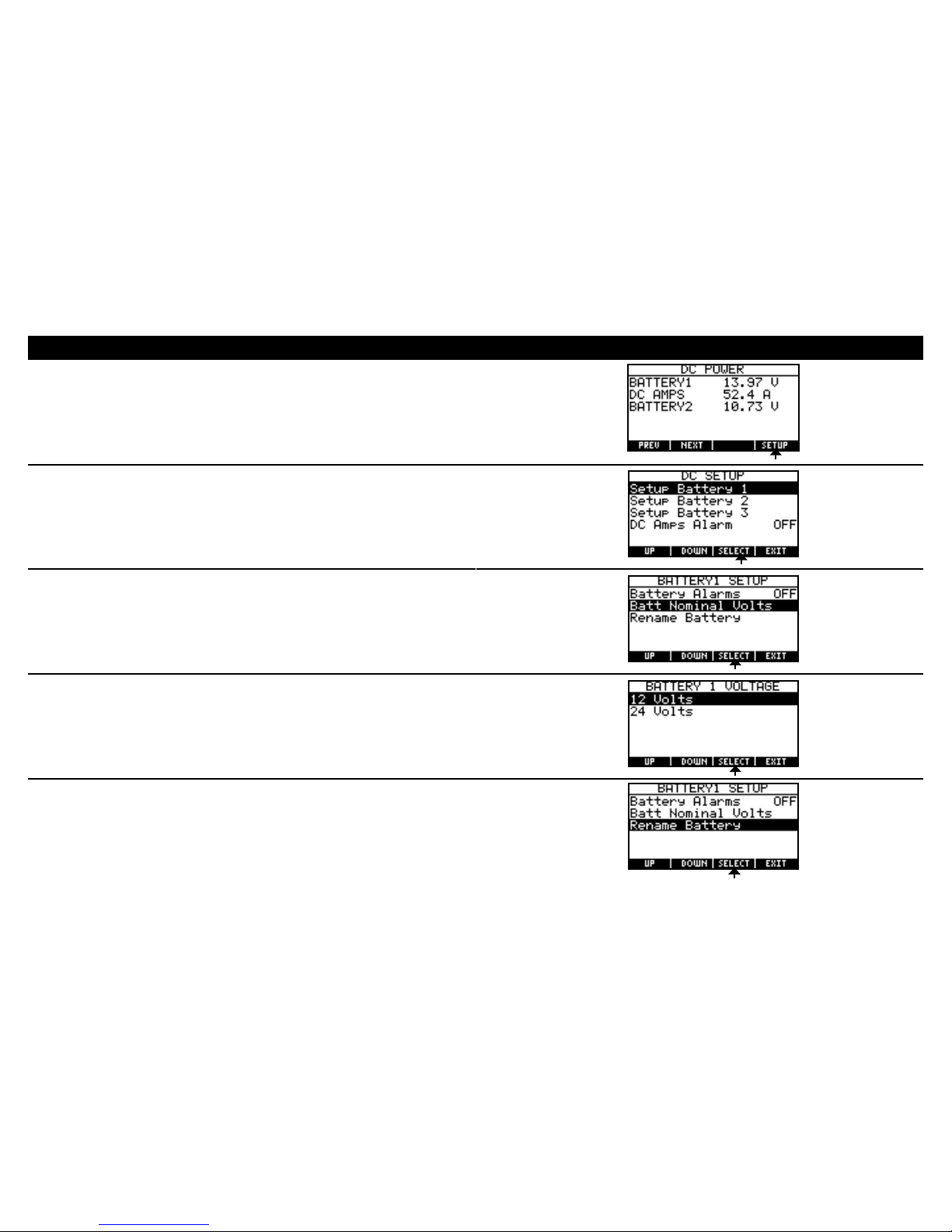
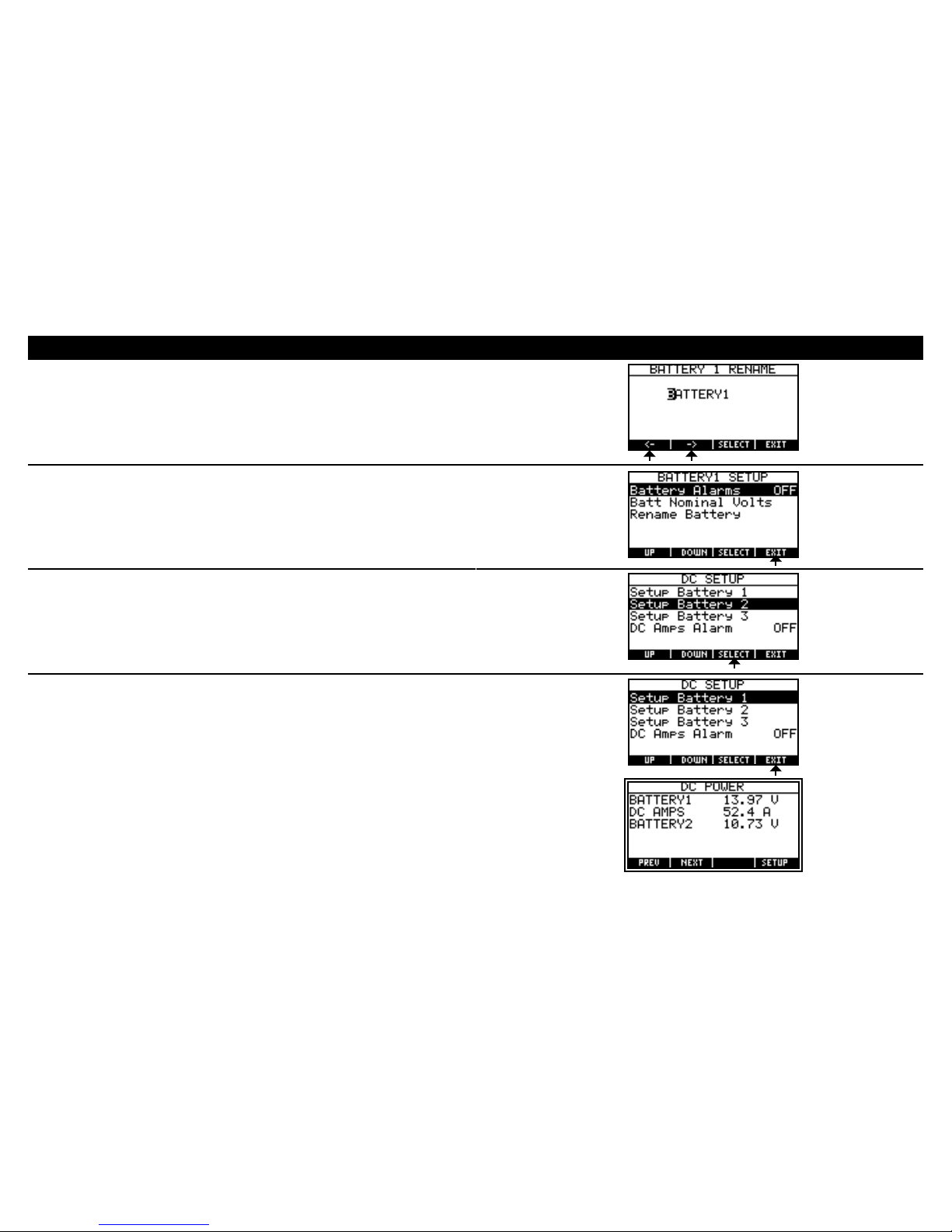
DC System Conguration
1. PagethroughmainscreensbypressingNEXTuntilthe
DC POWERpageisvisible.
2. PressSETUP.
3. ScrolltoandpressSELECTonbattery.
4. ScrolltoandpressSELECT on Batt Nominal Volts.
5. ScrolltoandpressSELECTondesirednominalvoltage.
6. ScrolltoandpressSELECT on Rename Battery.
Specicationssubjecttochange.Seewww.bluesea.comforcurrentinformation.
24
Specicationssubjecttochange.Seewww.bluesea.comforcurrentinformation.
23
DC System Conguration (continued)
7. SetbatterynameusingtheCharacterSelectionmethod.(page13)
8. Press EXIT
9. Repeatsteps2to8foreachbattery.
10. PressEXIT toreturntomainsystemscreens.
Specicationssubjecttochange.Seewww.bluesea.comforcurrentinformation.

26
Specicationssubjecttochange.Seewww.bluesea.comforcurrentinformation.
25
Tank Conguration
1. PagethroughmainscreensbypressingNEXTuntilthe
TANK STATUSpageisvisible.
2. PressSETUP.
3. ScrolltoandpressSELECT on tank.
4. ScrolltoandpressSELECT on Rename Tank.
5. SettanknameusingtheCharacterSelectionmethod.(page13)
6. PressEXIT
7. ScrolltoandpressSELECT on Display % or Vol.
Specicationssubjecttochange.Seewww.bluesea.comforcurrentinformation.

28
Specicationssubjecttochange.Seewww.bluesea.comforcurrentinformation.
27
Tank Conguration (continued)
8. ScrolltoandpressSELECTondesireddisplayformat.
9. ScrolltoandpressSELECT on Select Sender Type.
10. ScrolltoandpressSELECTondesiredsender.
11. Ifanultrasonicsensorisbeingusedscrolltoandpress SELECT on
Set Tank Depth.
12. SetthetankdepthusingtheSlideBarmethod.
13. PressSELECT.
Specicationssubjecttochange.Seewww.bluesea.comforcurrentinformation.

30
Specicationssubjecttochange.Seewww.bluesea.comforcurrentinformation.
29
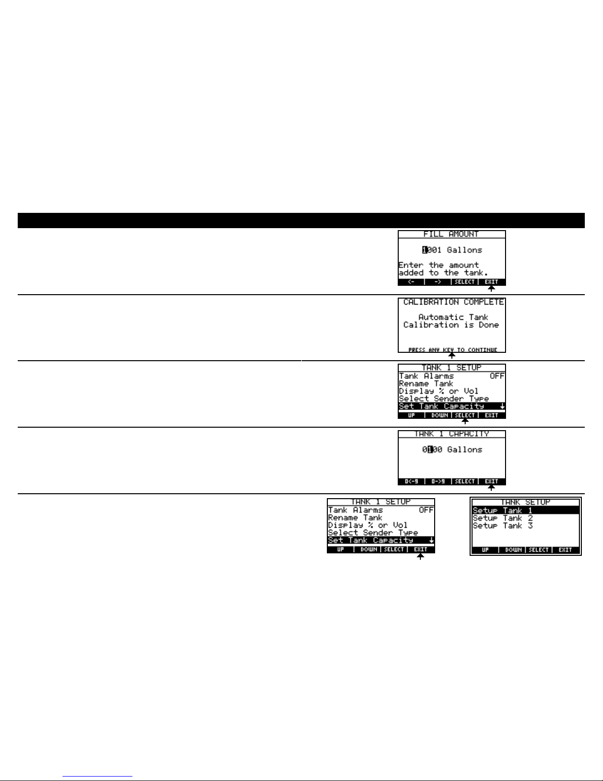
Tank Conguration
(continued)
TherearetwowaystocalibratetankswiththeVSM422:RectangularCali-
brationandAutoCalibration.Rectangulartanksaretankswheretheshapeof
thetankdoesnotchangebasedontheheight.AutoCalibrationisidealifa
non-rectangulartankisbeingused.UseeitherRectangularorAuto
Calibrationtocompletetankconguration.
Makesurethatthetanksensorisproperlyadjustedforthetankdepth.For
ultrasonicsensorsthismeanssettingthetankdepth.
Followtankcongurationsteps1–13onpages25–27fortanksetup.
Thenusethestepsbelowtocalibrateforarectangulartank.Thesteps
belowarenotrequiredifthemonitorwillbedisplayingthetankinpercent.
1.ScrolltoanpressSELECT on Set Tank Capacity
2.SettankvolumeusingtheCharacterSelectionmethod.(page13)
3.PressEXIT.
4.PressEXIT.
5.RepeatTankSetupstartingwithstep3forallremainingtanks.
Tank Conguration (Rectangular Calibration)
Specicationssubjecttochange.Seewww.bluesea.comforcurrentinformation.

32
Tankcalibrationismostaccurateifperformedwhenthetankisascloseto
emptyaspossible.
Auto Calibration Procedure Selection Charts
If the tank is near empty: ≤10% Full
(thecurrenttanklevelwillbeassumedtobetheemptypointbythemeter)
Theamountofliquidaddedduring
calibrationcanbemeasured
YES NO
Theemptytank
capacityisknown
YES Procedure1(page33) Procedure1(page33)
NO Procedure1(page33) Procedure1* (page33)
If the tank is not empty: >10%–30% Full
Theamountofliquidaddedduring
calibrationcanbemeasured
YES NO
Theemptytank
capacityisknown
YES Procedure2(page37) Procedure3† (page41)
NO Procedure3* † (page41) Procedure3* † (page41)
*Monitorwillonlybeabletocorrectlydisplaypercentage.Use100asthe
fulltankcapacity.
†Mustbeabletoestimatethepercentageofthetankthatislledatthestart
ofAutoCalibration.
Tank Conguration
(Auto Calibration)
Specicationssubjecttochange.Seewww.bluesea.comforcurrentinformation.
Afterfollowingsteps1–13onpages25–27,continuewiththeappropriate
AutoCalibrationprocedure.
WhenrunningtheAutoCalibrationitisimportantthatthecurrenttank’s
alarmsareturnedoffandthattheboatwillnottriggeranyalarmforother
systems.Ifanalarmoccurs,autocalibrationmustberunagainforaccurate
tankmetering.Itisrecommendedthattanklevelsareaslowassafely
possiblebeforerunningcalibration.Forgrayandblackwatertanks,fresh
watermaybeusedtollthetankduringcalibration.
TherearethreedifferentAutoCalibrationproceduresthatcanberun
dependingonwhatinformationisknown.UsetheAutoCalibration
ProcedureSelectionChartsonpage32todeterminetheneeded
informationandtheappropriateprocedurenumber.
31
Tank Conguration
(Auto Calibration)
Specicationssubjecttochange.Seewww.bluesea.comforcurrentinformation.

34
Specicationssubjecttochange.Seewww.bluesea.comforcurrentinformation.
33
Tank Conguration (Auto Calibration Procedure 1)
1.ScrolltoandpressSELECT on Set Tank Shape.
2.ScrolltoandpressSELECT on Use Auto Calibration.
3.ScrolltoandpressSELECT on Automatic Calibration.
4.WhentankisemptypressSELECT on Start Calibration.
Filltankatasteadyrate.
5.WhenthetankisfullpressSELECT.
Specicationssubjecttochange.Seewww.bluesea.comforcurrentinformation.
36
Specicationssubjecttochange.Seewww.bluesea.comforcurrentinformation.
35
6. Keepthedefaultllamount.PressEXIT.
7. Pressanykeytocontinue.
8.ScrolltoandpressSELECT on Set Tank Capacity.
9.Settankvolumetoknowntankvolumeormeteredllamountusingthe
CharacterSelectionmethod.(page13)
10.PressEXIT.
11.PressEXIT.
12.RepeatTankSetupstartingwithstep3forallremainingtanks.
Tank Conguration (Auto Calibration Procedure 1)
Specicationssubjecttochange.Seewww.bluesea.comforcurrentinformation.
Table of contents


